Routing Director Implementation
To determine the resources required to implement Routing Director, you must understand the fundamentals of the Routing Director underlying infrastructure.
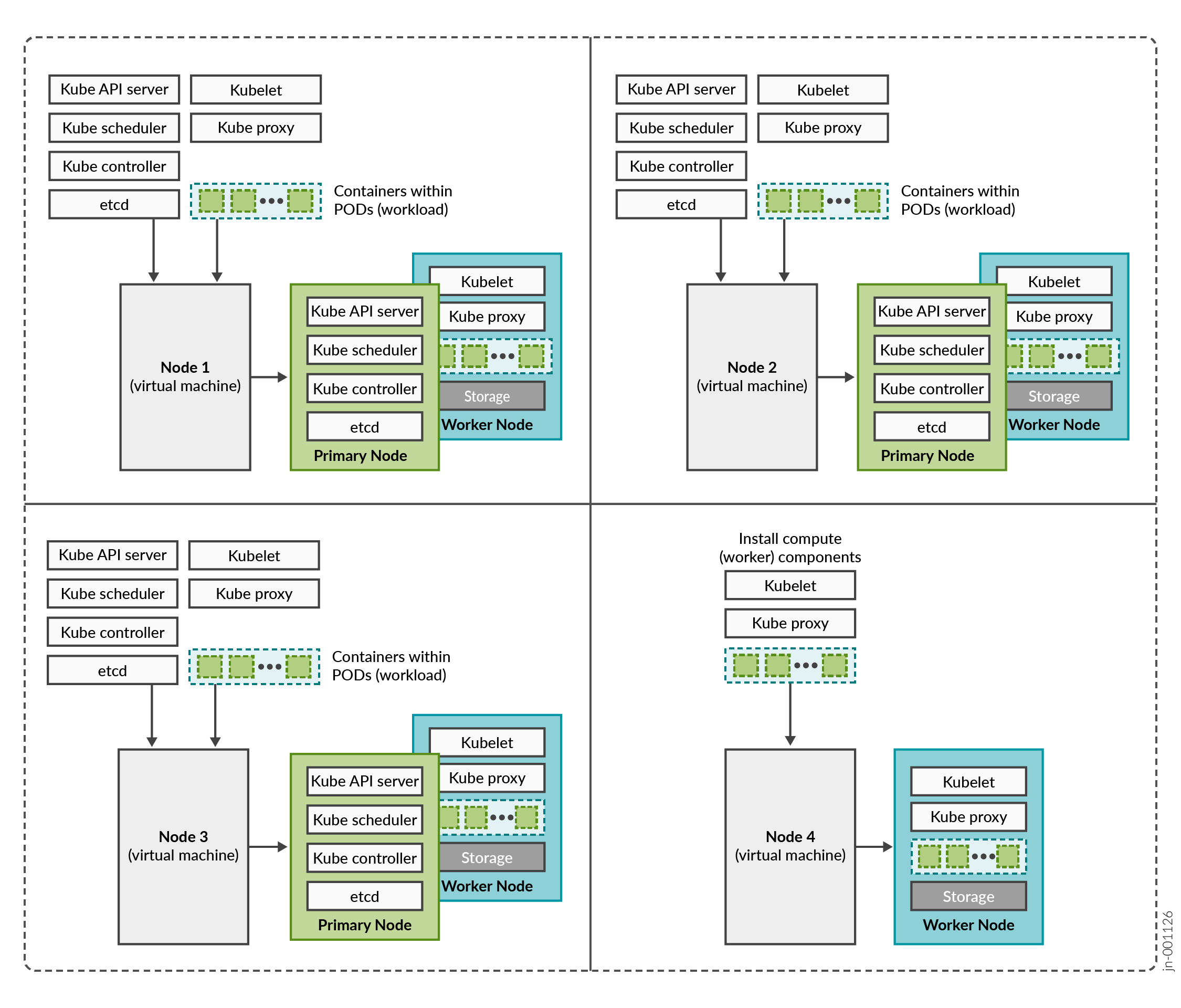
Routing Director is a collection of microservices that interact with one another through APIs and run within containers in a Kubernetes cluster. A Kubernetes cluster is a set of nodes or virtual machines (VMs) running containerized applications.
A Kubernetes cluster comprises one or more primary and worker nodes.
-
Control plane (primary) node—The primary node performs the Kubernetes control-plane functions.
-
Compute (worker) node—The worker node provides resources to run the pods. Worker nodes do not have control-plane function.
The two types of nodes can be deployed separately or co-located in the same VM. A single node can function as both primary and worker if the components required for both roles are installed in the same node.
In Routing Director, by default, the primary nodes also serve as worker nodes.
You need to consider the intended system's capacity (number of devices to be managed, use cases, and so on), the level of availability required, and the expected system's performance, to determine the following cluster parameters:
- Total number of nodes in the cluster
- Amount of resources on each node (CPU, memory, and disk space)
- Number of nodes acting as primary and worker nodes
The amount of resources on each node are described later in this guide in Routing Director System Requirements.
Routing Director Implementation
Routing Director is implemented on top of a Kubernetes cluster, which consists of one or more primary nodes and one or more worker nodes. Routing Director is implemented as a multinode cluster. At minimum, three nodes that function as both primary and worker nodesare required for a functional cluster.
This implementation not only improves performance but allows for high availability within the cluster:
-
Control plane high availability—The three nodes that function as both primary and worker nodes provide the required control plane redundancy. We do not support more than three primary nodes.
-
Workload high availability—For workload high availability and workload performance, you must have more than one worker. In Routing Director, the three nodes that function as both primary and worker nodes provide the required workload high availability. If your cluster contains four nodes, the fourth node functions as a worker only node providing additional workload high availability.
-
Storage high availability—For storage high availability, all the nodes provide Ceph storage.
A four-node cluster, where three nodes function as primary and worker nodes, and one node functions as a worker only node is the recommended and supported implementation.
However, you can also deploy Routing Director on a three-node cluster. The installation process is the same as that of a four-node cluster, except where you configure hardware resource requirements.
The rest of this document focuses on installing and configuring a four-node cluster. Any differences in configuring a three-node cluster are called out explicitly in the corresponding installation steps.
Cluster Nodes and Server High Availability
The Routing Director deployment cluster remains functional when a single node fails and when the maximum round trip latency between nodes is less than 25 ms.
To ensure that the cluster remains functional when a server fails, implement the cluster on four servers. The recommended implementation to maintain both server and node high availability is illustrated in Figure 2. This ensures that the cluster remains functional even if one of the servers fail.
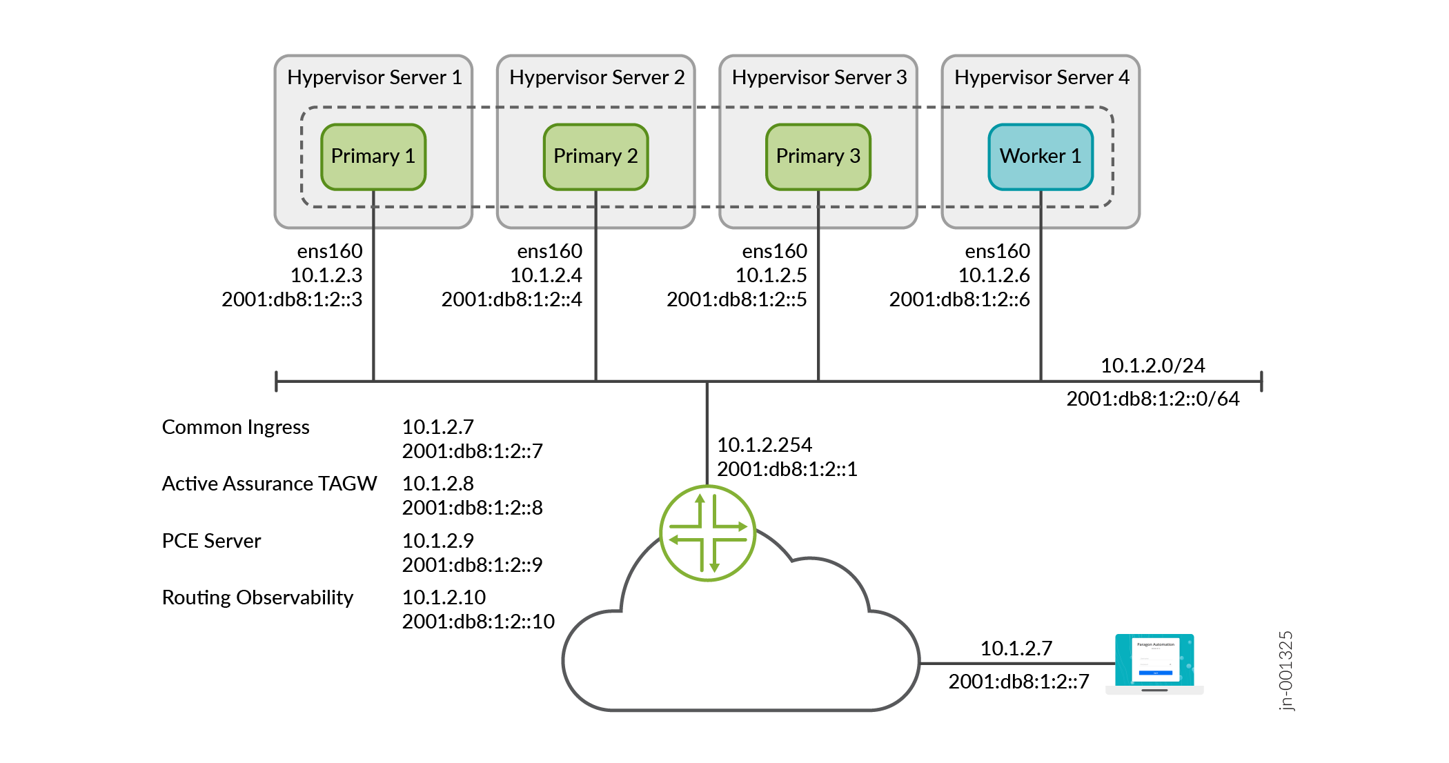
Note that, in this example, 10.1.2.7 is the VIP address for the GUI and is on the 10.1.2.0/24 network. You can reach 10.1.2.7 locally on the 10.1.2.0/24 network. You can also reach 10.1.2.7 externally by using NAT to translate the external IP address to 10.1.2.7.
The illustration displays a four-node cluster where the cluster nodes and VIP addresses are all in the same subnet. The cluster can have three nodes and the nodes and VIP addresses can also be located in different subnets.