Install Paragon Automation
This topic describes the steps you must perform to install Paragon Automation using an OVA or OVF bundle.
You (system administrator) can install Paragon Automation by downloading an OVA bundle. You can use the OVA bundle as a whole or extract OVF and .vmdk files from the OVA bundle and use the files to deploy the node virtual machines (VMs) on a VMware ESXi server. Paragon Automation runs on a Kubernetes cluster with at least three primary and worker nodes and one worker-only node. The installation is air-gapped but you need Internet access to download the OVA bundle to your computer.
If you are installing from a remote machine, you can instead create a local desktop installer VM, either on the same server where you want to install Paragon Automation or on a different server. The local desktop installer VM can be a basic Ubuntu desktop VM. This avoids having to download the files into your remote machine, and then running the installation from the remote machine. This is described in the Prepare the Nodes section.
To install Paragon Automation, you must create the node VMs using the downloaded OVA or OVF and .vmdk files. The software download files come prepackaged with the base OS and all packages required to create the VMs and deploy your Paragon Automation cluster. The VMs have an Ubuntu 22.04.4 LTS (Jammy Jellyfish) Linux base OS.
Once the VMs are created, you must configure each VM in the same way. When all the VMs are configured and prepared, you deploy the Paragon Automation cluster. You can deploy the cluster in either of the following ways:
Figure 1 illustrates the Paragon Automation installation process at a high-level.
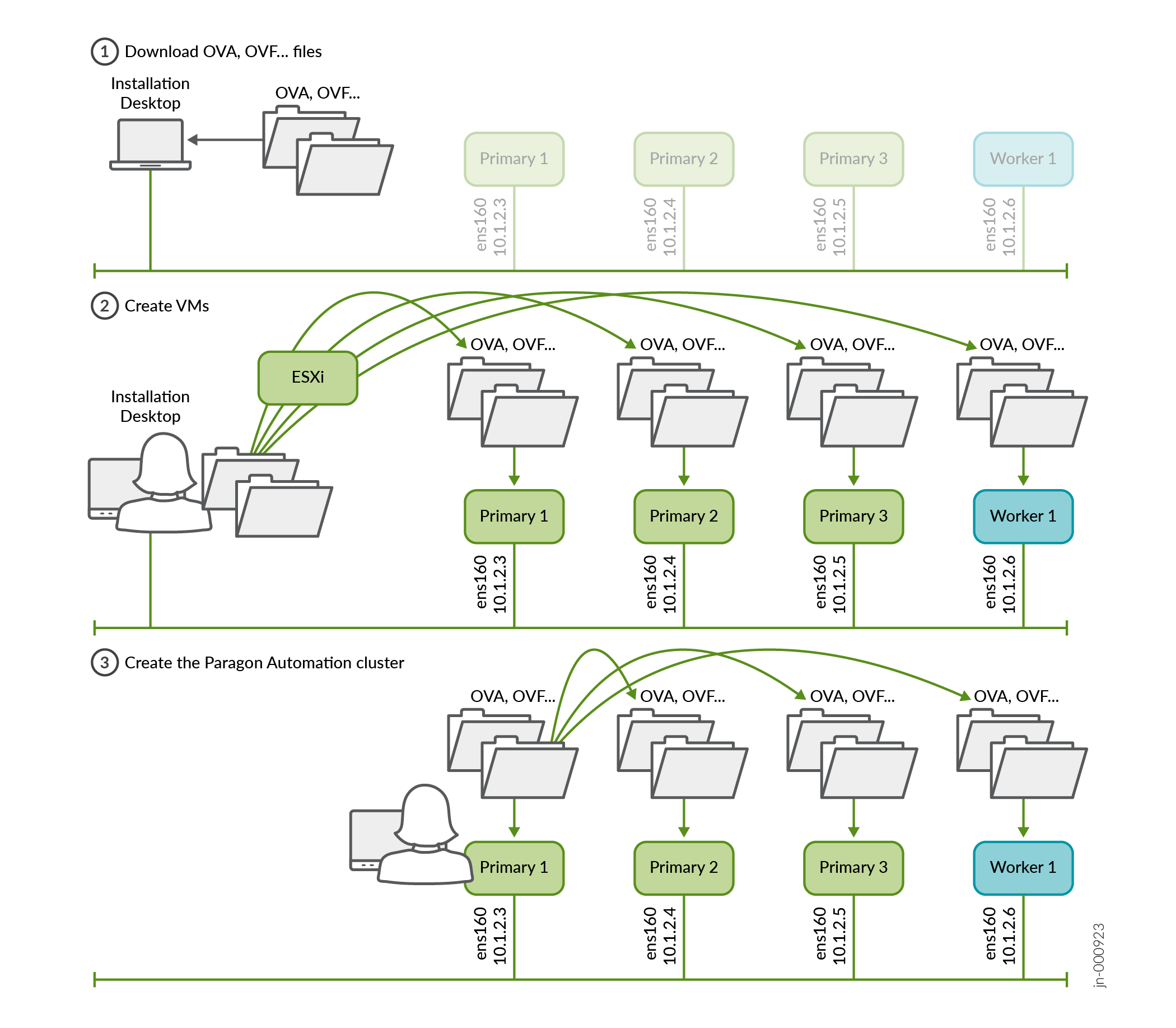
You create the VMs directly using the OVA/OVF bundles. You do not need to create the VMs separately with any running software (for example, Ubuntu), or explicitly create interfaces, install Docker separately and so on. These are all automatically created and configured when you create the VMs using the OVA/OVF bundles.
To prepare the VMs, perform the following steps.
Prepare the Nodes
To prepare the nodes you must create and configure the VMs.
-
Download the Paragon Automation Installation OVA file from the Juniper Paragon Automation software download site. The OVA is used to create the node VMs and deploy your cluster.
Note that the actual filename will include the release date in it, such as paragon-2.0.0-0515.ova.
The file is large in size and it might take considerable time to download it and then create the VMs from your computer. So, we recommend that you create a local installer VM, which can be a basic Ubuntu desktop VM, either on the same server where you want to install Paragon Automation or on a different server. You must be able to download the OVA file to this local installer VM and you must have enough space on the VM to store the file. Configure connectivity to the management IP addresses of the servers as show in Figure 2.
Figure 2: Local Installer VM to download the OVA/OVF files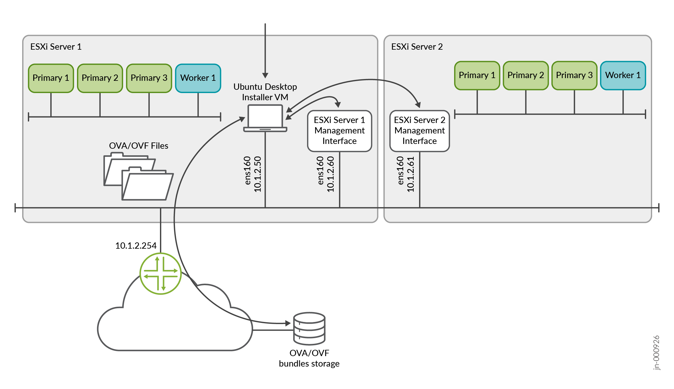
-
(Optional) Validate the integrity of the OVA file. If you are using an Ubuntu desktop, use the following command:
root@ubuntu:~$ sha512sum paragon-2.0.0-0515.ova
7deda68aae8ba6399aa95d5365a659a8d579c5562811ebe588972cf0c5107337628370d78dcbdb56ab8ea97e73b7597f3a5ff06e9f501706bd8954b7454b86d2 paragon-2.0.0-0515.ova
Verify that the number displayed onscreen is the same as the SHA512 checksum number available on the Juniper Paragon Automation software download site. Click Checksums to view the valid SHA512 checksum.
-
After verifying the integrity, create the node VMs. You can use the OVA as a whole to create the VMs.
Alternatively, extract and use the OVF and .vmdk files from the OVA to create your VMs. To extract the files, use the following command:
tar -xvf paragon-2.0.0-0515.ovaIf your installation desktop is running Windows, you can download and use the tar utility from https://gnuwin32.sourceforge.net/packages/gtar.htm to extract the files.
Note:If you are using a stand-alone ESXi 8.0 server without vCenter, due to a limitation of the VMware host client, you cannot upload large OVA files to the client. In such cases, you must extract and use the OVF, .vmdk, and .nvram files to create your VMs.
-
From your Web browser, connect and log in to the VMware ESXi 8.0 server where you will install Paragon Automation.
If you are using a local installer VM, use the browser in the VM to connect to the VMware ESXi server.
-
Create the node VMs.
Perform the following steps to create the VMs.
-
Right-click the Host icon and select Create/Register VM.
The New virtual machine wizard appears.
-
On the Select creation type page, select Deploy a virtual machine from an OVF or OVA file.
Click Next.
-
On the Select OVF and VMDK files page, enter a name for the node VM.
Click to upload or drag and drop the OVA file or the OVF file along with the .vmdk files.
Review the list of files to be uploaded and click Next.
-
On the Select storage page, select the appropriate datastore that can accommodate 300-GB SSD for the node VM. Note that SSD is mandatory.
Click Next. The extraction of files takes a few minutes.
-
On the Deployment options page:
-
Select the virtual network to which the node VM will be connected.
-
Select the Thick disk provisioning option.
-
Enable the VM to power on automatically.
Click Next.
-
-
On the Ready to complete page, review the VM settings.
Click Finish to create the node VM.
Note:If you used the OVF and .vmdk files to create your VMs and the VM creation failed, retry creating the VMs with the .nvram file. On step 5.c, upload the .nvram file along with the OVF and .vmdk files. For standalone ESXi 8.0 servers without vCenter, you must upload the .nvram file as well.
-
Repeat steps 5.a through 5.f for the other three node VMs. Enter appropriate VM names when prompted.
-
(Optional) Verify the progress of the VM creation in the Recent tasks section at the bottom of the page. When a VM is created, it appears in the VMware Host Client inventory under Virtual Machines.
-
When all the VMs have been created, verify that they have the correct specifications and are powered on.
-
-
Configure the node VMs
When all the node VMs are created, perform the following steps to configure them.
-
Connect to the node VM Web console of the first VM. You are logged in as root automatically.
-
You are prompted to change your password immediately. Enter and re-enter the new password. You are automatically logged out of the VM.
Note:We recommend that you enter the same password for all the VMs. If you configure different passwords for the VMs, enter the different passwords correctly when requested to:
-
Generate SSH keys for the cluster nodes when deploying the cluster using Paragon Shell.
-
Enter the passwords for the VMs when deploying the cluster using the deployment wizard.
-
-
When prompted, log in again as root user with the newly configured password.
-
Configure the following information when prompted.
Table 1: VM Configuration Wizard Prompt
Action
Do you want to set up a Hostname? (y/n)
Enter y to configure a hostname.
Please specify the Hostname
Enter an identifying hostname for the VM. For example: Primary1. The hostname should be under 64 characters and can include alphanumeric and some special characters.
If you do not enter a hostname, a default hostname in the format
controller-<VM-IP-address-4th-octet> is assigned.Note:Since you are deploying the cluster from one node, and entering the IP addresses of the other nodes during the cluster configuration process, the roles are assigned automatically. The first three nodes to be configured are the primary and worker nodes and the last node is the worker-only node.
The hostnames (and whether or not they match the role of the node), will not affect the operations of the cluster. However, for management purposes, we recommend that you pay attention to how you name the nodes and the order in which you entered their addresses during the cluster creation steps.
We do not support changing the hostname after the cluster has been installed.
Do you want to set up Static IP (preferred)? (y/n)
Enter y to configure an IP address for the VM.
Please specify the IP address in CIDR notation
Enter the IP address in the CIDR notation. For example, 10.1.2.3/24.
Note:If you enter 10.1.2.3 instead of 10.1.2.3/24 you will get an Invalid IP address error message.
Please specify the Gateway IP
Enter the gateway IP address.
Please specify the Primary DNS IP
Enter the primary DNS IP address.
Please specify the Secondary DNS IP Enter the secondary DNS IP address.
-
When prompted if you are sure to proceed, review the information displayed, type y and press Enter.
-
You are logged in to Paragon Shell.
-
-
(Optional) Before you proceed to deploy the cluster, verify that the NTP server(s) is reachable. On any one of the cluster nodes, type
start shell. At the#prompt, ping the server using theping ntp-servers-name-or-addresscommand. If the ping is unsuccessful, use an alternate NTP server.
You have completed the node preparation steps and are ready to deploy the cluster using either Paragon Shell or the deployment wizard.
Deploy the Cluster Using Paragon Shell
Perform the following steps to deploy the Paragon Automation cluster using Paragon Shell CLI.
-
Go back to the first node VM (Primary1). If you have been logged out, log in again using SSH, as root with the previously configured password. You are placed in Paragon Shell operational mode.
********************************************************************* WELCOME TO PARAGON SHELL! You will now be able to execute Paragon CLI commands! ********************************************************************* root@eop> -
To configure the cluster, enter the configuration mode in Paragon Shell.
root@eop> configure
Entering configuration mode

[edit]
-
Configure the following cluster parameters.
root@eop# set paragon cluster nodes kubernetes 1 address 10.1.2.3

[edit]
root@eop# set paragon cluster nodes kubernetes 2 address 10.1.2.4

[edit]
root@eop# set paragon cluster nodes kubernetes 3 address 10.1.2.5

[edit]
root@eop# set paragon cluster nodes kubernetes 4 address 10.1.2.6

[edit]
root@eop# set paragon cluster ntp ntp-servers pool.ntp.org

[edit]
root@eop# set paragon cluster common-services ingress ingress-vip 10.1.2.7

[edit]
root@eop# set paragon cluster applications active-assurance test-agent-gateway-vip 10.1.2.8

[edit]
root@eop# set paragon cluster applications web-ui web-admin-user "user-admin@juniper.net"

[edit]
root@eop# set paragon cluster applications web-ui web-admin-password Userpasswd

[edit]
Where:
The IP addresses of
kubernetesnodes with indexes 1 through 4 must match the static IP addresses configured on the node VMs. The Kubernetes nodes with indexes 1,2 and 3 are the primary and worker nodes, the node with index 4 is the worker-only node.ntp-serversis the NTP server to sync to.web-admin-userandweb-admin-passwordare the e-mail address and password that the first user can use to log in to the Web GUI.ingress-vipis the VIP address for the generic ingress IP address.test-agent-gateway-vipis the VIP address for the Paragon Active Assurance Test Agent gateway.The VIP addresses are added to the outbound SSH configuration that is required for a device to establish a connection with Paragon Automation.
-
(Optional) If you want to configure hostnames for generic ingress and Paragon Active Assurance Test Agent gateway, configure the following:
root@eop# set paragon cluster common-services ingress system-hostname ingress-vip-dns-hostname

[edit]
root@eop# set paragon cluster applications active-assurance test-agent-gateway-hostname nginx-ingress-controller-hostname

[edit]
Where:
system-hostnameis the hostname for the generic ingress virtual IP address.test-agent-gateway-hostnameis the hostname for the Paragon Active Assurance Test Agent gateway virtual IP address.When you configure hostnames, the hostnames are added to the outbound SSH configuration instead of the VIP addresses.
-
(Optional) Configure the following settings for SMTP-based user management.
root@eop# set paragon cluster mail-server smtp-allowed-sender-domains sender-domains

[edit]
root@eop# set paragon cluster mail-server smtp-relayhost relayhost-hostname

[edit]
root@eop# set paragon cluster mail-server smtp-relayhost-username relayhost-username

[edit]
root@eop# set paragon cluster mail-server smtp-relayhost-password relayhost-password

[edit]
root@eop# set paragon cluster mail-server smtp-sender-email sender-e-mail-address

[edit]
root@eop# set paragon cluster mail-server smtp-sender-name sender-name

[edit]
root@eop# set paragon cluster papi papi-local-user-management False

[edit]
Where:
sender-domains are the e-mail domains from which Paragon Automation sends e-mails to users.
relayhost-hostname is the name of the SMTP server that relays messages.
relayhost-username (optional) is the user name to access the SMTP (relay) server.
relayhost-password (optional) is the password for the SMTP (relay) server.
sender-e-mail-address is the e-mail address that appears as the sender's e-mail address to the e-mail recipient.
sender-name is the name that appears as the sender’s name in the e-mails sent to users from Paragon Automation.
papi-local-user-management Falsedisables local user management.Note:SMTP configuration is optional at this point. SMTP settings can be configured after the cluster has been deployed also. For information on how to configure SMTP after cluster deployment, see Configure SMTP Settings in Paragon Shell.
-
(Optional) Install custom user certificates. Note, before you install user certificates, you must have copied the custom certificate file and certificate key file to the /root/epic/config folder in the Linux root shell of the node from which you are deploying the cluster.
root@eop# set paragon cluster common-services ingress user-certificate use-user-certificate true

[edit]
root@eop# set paragon cluster common-services ingress user-certificate user-certificate-filename "certificate.cert.pem"

[edit]
root@eop# set paragon cluster common-services ingress user-certificate user-certificate-key-filename "certificate.key.pem"

[edit]
Where:
certificate.cert.pem is the user certificate file name.
certificate.key.pem is the user certificate key file name.
Note:Installing certificates is optional at this point. You can configure Paragon Automation to use custom user certificates after cluster deployment also. For information on how to install user certificates after cluster deployment, see Install User Certificates.
-
Commit the configuration and exit configuration mode.
root@eop# commit
commit complete

[edit]
root@eop# exit
Exiting configuration mode

root@eop>
-
Generate the configuration files.
root@eop> request paragon config
Paragon inventory file saved at /epic/config/inventory
Paragon config file saved at /epic/config/config.yml
The inventory file contains the IP addresses of the VMs.
The config.yml file contains minimum Paragon Automation cluster parameters required to deploy a cluster.
The
request paragon configcommand also generates a config.cmgd file in the config directory. The config.cmgd file contains all thesetcommands that you executed in 3. If the config.yml file is inadvertently edited or corrupted, you can redeploy your cluster using theload set config/config.cmgdcommand in the configuration mode. -
Generate ssh keys on the cluster nodes.
When prompted, enter the SSH password for the VMs. Enter the same password that you configured to log in to the VMs.
root@eop> request paragon ssh-key Setting up public key authentication for ['10.1.2.3','10.1.2.4','10.1.2.5','10.1.2.6'] Please enter SSH username for the node(s): root Please enter SSH password for the node(s): password checking server reachability and ssh connectivity ... Connectivity ok for 10.1.2.3 Connectivity ok for 10.1.2.4 Connectivity ok for 10.1.2.5 Connectivity ok for 10.1.2.6 SSH key pair generated in 10.1.2.3 SSH key pair generated in 10.1.2.4 SSH key pair generated in 10.1.2.5 SSH key pair generated in 10.1.2.6 copied from 10.1.2.3 to 10.1.2.3 copied from 10.1.2.3 to 10.1.2.4 copied from 10.1.2.3 to 10.1.2.5 copied from 10.1.2.3 to 10.1.2.6 copied from 10.1.2.4 to 10.1.2.3 copied from 10.1.2.4 to 10.1.2.4 copied from 10.1.2.4 to 10.1.2.5 copied from 10.1.2.4 to 10.1.2.6 copied from 10.1.2.5 to 10.1.2.3 copied from 10.1.2.5 to 10.1.2.4 copied from 10.1.2.5 to 10.1.2.5 copied from 10.1.2.5 to 10.1.2.6 copied from 10.1.2.6 to 10.1.2.3 copied from 10.1.2.6 to 10.1.2.4 copied from 10.1.2.6 to 10.1.2.5 copied from 10.1.2.6 to 10.1.2.6Note:If you have configured different passwords for the VMs, ensure that you enter corresponding passwords when prompted.
-
Deploy the cluster.
root@eop> request paragon deploy cluster
Process running with PID: 231xx03
To track progress, run 'monitor start /epic/config/log'
After successful deployment, please exit Paragon-shell and then re-login to the host to finalize the setup
The cluster deployment begins and takes over an hour to complete.
-
(Optional) Monitor the progress of the deployment onscreen.
root@eop> monitor start /epic/config/log
The progress of the deployment is displayed. Deployment is complete when you see an output similar to this onscreen.
<output snipped>

PLAY RECAP *********************************************************************
10.1.2.3              : ok=1648 changed=636  unreachable=0    failed=0    skipped=417  rescued=0    ignored=9
10.1.2.4              : ok=168  changed=79   unreachable=0    failed=0    skipped=115  rescued=0    ignored=0
10.1.2.5              : ok=168  changed=79   unreachable=0    failed=0    skipped=115  rescued=0    ignored=0
10.1.2.6              : ok=168  changed=82   unreachable=0    failed=0    skipped=108  rescued=0    ignored=0

Monday 08 April 2024  19:00:19 +0000 (0:00:06.528)       1:03:24.322 **********
===============================================================================
user-registry : Push Docker Images from local registry to paragon registry - 877.85s
kubernetes/addons/rook : Wait for Object-Store ------------------------ 403.53s
jcloud/airflow2 : Install Helm Chart ---------------------------------- 183.14s
Install Helm Chart ---------------------------------------------------- 122.57s
kubernetes/addons/postgres-operator : Make sure postgres is fully up and accepting request using regular user - 113.31s
delete existing install config-map - if any ---------------------------- 91.59s
Save installer config to configmap ------------------------------------- 82.56s
Install Helm Chart ----------------------------------------------------- 78.55s
jcloud/papi : Install Helm Chart --------------------------------------- 68.59s
systemd ---------------------------------------------------------------- 64.85s
kubernetes/multi-master-rke2 : start rke2 server on other master ------- 60.60s
kubernetes/multi-master-rke2 : start rke2 server on other master ------- 58.66s
Create Kafka Topics ---------------------------------------------------- 58.50s
paa/timescaledb : Make sure postgres is fully up and accepting request using regular user -- 56.30s
kubernetes/multi-master-rke2 : start rke2 server on 1st master --------- 50.92s
kubernetes/addons/metallb : Apply MetalLB configuration ---------------- 48.86s
Check if kafka container is up ----------------------------------------- 45.22s
jcloud/papi : wait for papi rest api ----------------------------------- 43.13s
Install Helm Chart ----------------------------------------------------- 36.27s
user-registry : Push Helm Charts to paragon registry ------------------- 36.09s
Playbook run took 0 days, 1 hours, 03 minutes, 24 seconds
registry-5749
root@eop>
Alternatively, if you did not choose to monitor the progress of the deployment onscreen using the
monitorcommand, you can view the contents of the log file using thefile show /epic/config/logcommand. The last few lines of the log file must look similar to the sample output. We recommend that you check the log file periodically to monitor the progress of the deployment. -
When deployment is complete, log out of the VM and log in again to Paragon Shell.
Upon successful completion of the deployment, the application cluster is created.
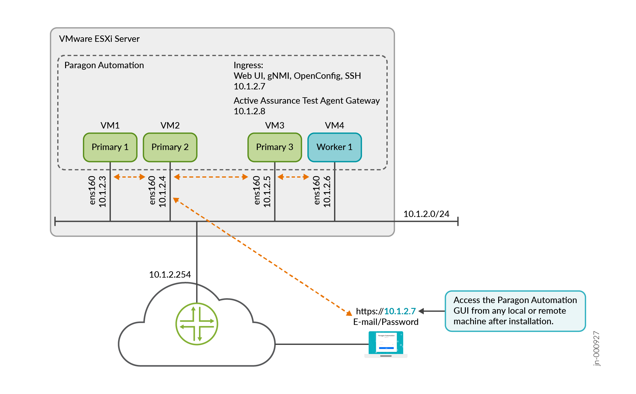
The console output displays the Paragon Shell welcome message and the IP addresses of the four nodes (called Controller-1 through Controller-4), the Paragon Active Assurance Test Agent gateway VIP address, the Web admin user e-mail address, and Web GUI IP address.
Welcome to Juniper Paragon Automation OVA


This VM 10.1.2.3 is part of an EPIC on-prem system.
===============================================================================
Controller IP    :  10.1.2.3, 10.1.2.4, 10.1.2.5, 10.1.2.6
PAA Virtual IP   :  10.1.2.8
UI               :  https://10.1.2.7
Web Admin User   :  admin-user@juniper.net
===============================================================================
ova: 20240503_2010
build: eop-release-2.0.0.6928.g6be8b6ce52

***************************************************************
                WELCOME TO PARAGON SHELL!
     You will now be able to execute Paragon CLI commands!
***************************************************************
root@Primary1>
The CLI command prompt displays your login username and the node hostname that you configured previously. For example, if you entered Primary1 as the hostname of your primary node, the command prompt is
root@Primary1
                                >
.
Figure 3 illustrates a Paragon Automation cluster post-installation.
You can now verify the cluster deployment and log in to the Web GUI. See Log in to the Web GUI.
Deploy the Cluster Using The Deployment Wizard
If you haven't deployed the cluster using Paragon Shell, perform the following steps to deploy the Paragon Automaton cluster using the interactive deployment wizard from the Linux root shell.
-
Go back to the first node VM (Primary1) and log in as root with the previously configured password. You are in the Paragon Shell operational mode.
-
Exit Paragon Shell. Type
exitto go back to the Linux root shell. -
When prompted whether you want to create a cluster, type y and press Enter.
Note:You can launch the deployment wizard to create a cluster at any time using the
setupcommand. -
Configure the following information when prompted.
Table 2: VM Deployment Wizard Prompt
Action
Please specify the list of available IPs
Enter the VIP addresses as a list in the format,
10.1.2.3, 10.1.2.4, or as a range in the format,10.1.2.3-10.1.2.4.Please specify Controller-2 IP
Please specify Controller-3 IP
Please specify Controller-4 IP
Enter the IP addresses of the second, third, and fourth VMs to correspond to Controller-2, Controller-3, and Controller-4 VMs.
These IP addresses must match the static IP addresses configured on the nodes.
Please specify Web Admin Email
Enter the e-mail address of the first user to log in to the Paragon Automation Web GUI. This user can be the system administrator or any other designated user. This user has superuser privileges and can create additional users.
Please specify Web Admin Password
Please specify Web Admin Password (again)
Enter a password that the first user can use to log in to the Web GUI.
Re-enter to confirm the password.
Please specify NTP server
Enter the NTP server IP address. Ensure that the NTP server is reachable and no firewall is blocking access to the server from the VM network.
-
When prompted whether you want to proceed, type y and press Enter.
-
When prompted, enter the SSH password for the VMs. Enter the same password that you configured to log in to the VMs.
Note:If you have configured different passwords for the VMs, ensure that you enter the correct corresponding passwords when prompted.
The cluster deployment begins. The deployment takes over an hour to complete.
-
Upon successful completion of the deployment, the application cluster is created and you are logged in to Paragon Shell.
The console output displays the four Controller IP addresses, the Paragon Active Assurance Test Agent gateway VIP address, the Web GUI VIP address, and the Web admin user e-mail address . The first VIP address in the list of VIP addresses that you entered while configuring the cluster is assigned to the Web GUI and the second VIP address is assigned to the Test Agent gateway.
The Application Cluster is created.This VM 10.1.2.3 is part of an EPIC on-prem system. =============================================================================== Controller IP : 10.1.2.3, 10.1.2.4, 10.1.2.5, 10.1.2.6 PAA Virtual IP : 10.1.2.8 UI : https://10.1.2.7 Web Admin User : user-admin@juniper.net =============================================================================== ova: 20240503_2010 build: eop-release-2.0.0.6928.g6be8b6ce52 *************************************************************** WELCOME TO PARAGON SHELL! You will now be able to execute Paragon CLI commands! *************************************************************** root@Primary1> -
Log out of the node VM and log in again to Paragon Shell to see the updated command prompt. The CLI command prompt displays your log in user name and the node hostname that you configured previously. For example, if you entered Primary1 as the hostname of your primary node, the command prompt is
root@Primary1 >. -
(Optional) Configure SMTP-based user management. To configure SMTP, perform the steps described in Configure SMTP Settings in Paragon Shell.
-
(Optional) Upload custom user certificates. To configure Paragon Automation to use custom user certificates, perform the steps described in Install User Certificates.
-
(Optional) Configure hostnames for common ingress and Paragon Active Assurance Test Agent gateway using Paragon Shell, perform the following steps:
root@Primary1> configure
Entering configuration mode

root@Primary1# set paragon cluster common-services ingress system-hostname ingress-vip-dns-hostname


[edit]
root@Primary1# set paragon cluster applications active-assurance test-agent-gateway-hostname nginx-ingress-controller-hostname


[edit]
root@Primary1# commit
commit complete

[edit]
root@Primary1# exit
Exiting configuration mode

root@Primary1> request paragon config
Paragon inventory file saved at /epic/config/inventory
Paragon config file saved at /epic/config/config.yml
root@Primary1> request paragon deploy cluster input "-t apps"
Process running with PID: 23xx022
To track progress, run 'monitor start /epic/config/log'
Where:
system-hostnameis the hostname for the generic ingress IP address.test-agent-gateway-hostnameis the hostname for the Paragon Active Assurance Test Agent gateway IP address.
You can now verify the cluster deployment and log in to the Web GUI.
Figure 3 illustrates a Paragon Automation cluster post-installation.
Log in to the Web GUI
After the cluster has been deployed, you can verify the deployment (optionally), and log in to the Web GUI using the information you entered during the deployment.
-
(Optional) Verify the deployment.
-
Verify cluster details.
root@Primary1 > show paragon cluster details
Storage and Controller Node IPs: 10.1.2.3, 10.1.2.4, 10.1.2.5, 10.1.2.6
-
Verify cluster node details.
root@Primary1 > show paragon cluster nodes
NAME           STATUS   ROLES                       AGE     VERSION
Primary1   Ready    control-plane,etcd,master   4h12m   v1.28.6+rke2r1
Primary2   Ready    control-plane,etcd,master   4h12m   v1.28.6+rke2r1
Primary3   Ready    control-plane,etcd,master   4h11m   v1.28.6+rke2r1
Worker1    Ready    influxdb-worker,worker      4h11m   v1.28.6+rke2r1
-
-
Log in to the Web GUI.
-
Enter https://web-ui-ip-address in a Web browser to access the Paragon Automation login page. web-ui-ip-address is the URL displayed on your console after the cluster deployment is complete.
-
Enter the Web admin user e-mail and password that you configured previously to log in to Paragon Automation. The Web admin user e-mail is also displayed on your console after the cluster deployment is complete
You are logged in to the Paragon Automation GUI and are directed to the New Account page from where you can create a new Organization. For more information, see User Activation and Login.
-