WAN Link Redundancy in Enterprise Hubs Using Aggregated Ethernet
SUMMARY Learn about aggregated Ethernet links (AE), how to manually configure LAG and LACP on an enterprise hub, and enable AE links on the enterprise hub WAN links.
Aggregated Ethernet Links in Enterprise Hubs
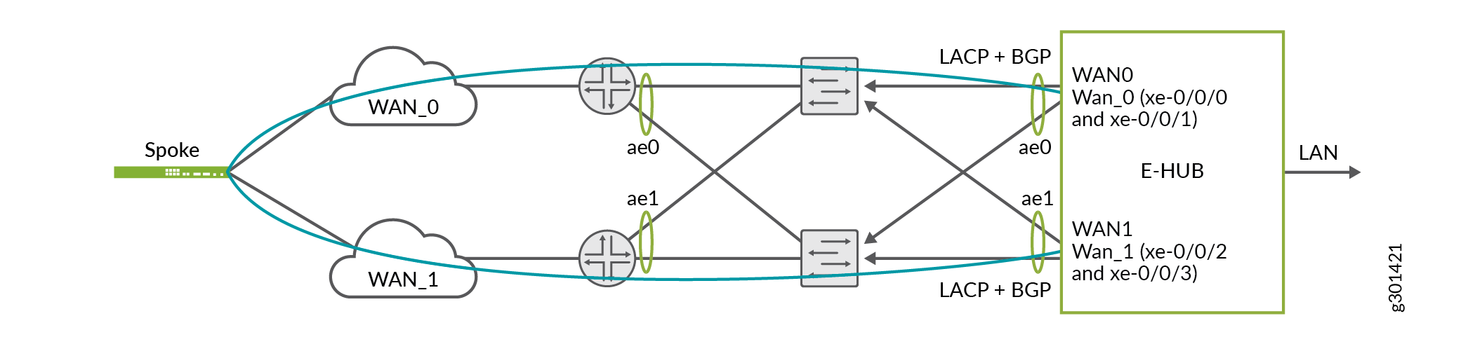
In CSO Release 6.0.0, a service provider or an OpCo Administrator can aggregate full-duplex gigabit Ethernet WAN links into a single logical aggregated Ethernet (aex) link or link aggregation group (LAG) bundle, as defined by the IEEE 802.3ad standard. Aggregated Ethernet (AE) links topology (shown in Figure 1) allows data traffic to flow between two WAN Ethernet interfaces operating at the same speed. This results in WAN redundancy and improves availability even if one physical link fails, as data traffic can flow through the alternative member in the aggregated Ethernet interface.
AE can be configured on WAN links of SRX Series enterprise hub devices. Provisioning LAG bundles in an enterprise hub involves three processes: pre-staging an SRX device, modifying the SRX device template, and enabling aggregated Ethernet on physical WAN ports. The pre-staging configuration of LAG bundle (aggregated Ethernet interface) is performed by service providers or operating companies.
Figure 1 shows the topology with LAG bundle configurations deployed during the pre-staging of an enterprise hub. Two gigabit Ethernet interfaces — xe-0/0/0 and xe-0/0/1 — are bundled together into one aggregated Ethernet interface (such as ae0). Similarly, xe-0/0/2 and xe-0/0/3 are configured to form ae1. If xe-0/0/0 fails, data traffic is switched to the xe-0/0/1 interface in ae0. Hence, data traffic continues to flow through the same WAN_0 port configured for AE. The branch site does not have to do WAN link switchover because of hub WAN link failure.
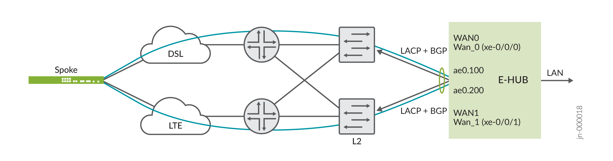
Starting in Release 6.1.0, CSO supports aggregated Ethernet interfaces with VLAN tagging on enterprise hub WAN links, thereby allowing you to ensure WAN link redundancy with lesser number of ports. Figure 2 illustrates a scenario where a VLAN-tagged aggregated Ethernet interface containing two member links is used to provide link redundancy for two WAN links. See .
The Link Aggregation Control Protocol (LACP), the protocol defined in IEEE 802.3ad, monitors the interfaces in the aggregated Ethernet link. LACP initiates and establishes LAG connection between the WAN aggregated Ethernet interfaces in enterprise hub and the remote device, monitors the AE interfaces for link failures, and dynamically switches the traffic between member links in an AE interface. LACP flags an AE link down only if all physical member links are operationally down.
After configuring LAG and LACP on the enterprise hub, an SP or OpCo Administrator can modify the device template for enterprise hub in CSO to map physical WAN ports — WAN_0 and WAN_1 — to aex links. Tenant Administrators must enable aggregated Ethernet on WAN ports (while adding an enterprise hub site in Customer Portal).
: Links in the aggregated Ethernet bundle support MPLS and Internet data traffic with only Ethernet as the access type for the underlay. VLAN tagging is not supported on aggregated Ethernet interfaces.
Configuration Guidelines for Aggregated Ethernet on WAN Links
Note the following guidelines before you configure aggregated Ethernet or LAG bundle on enterprise hub devices.
In CSO Release 6.0.0, you must manually configure LAG bundles on the enterprise hub device before zero touch provisioning (ZTP) is initiated to provision an enterprise hub site.
You must configure link aggregation groups within a configuration group and not at the root level. For example,
set groups WANredundancy interfaces xe-0/0/0 gigether-options 802.3ad ae0. In CSO, LAG configured at the root level will be removed when sites are provisioned through ZTP.Ensure that the LAG configuration group name is unique. The configuration group name must not be the same as groups CSO uses to configure devices. You need to also ensure that the LAG groups used in WAN links are different from LAG groups configured for LAN links.
Example: Configure Aggregated Ethernet in Enterprise Hub Devices
Table 1 describes an example configuration snippet for aggregated Ethernet links on enterprise hub devices.
You must execute all commands in configuration mode.
Configuration Steps |
Commands |
|---|---|
Step 1: Specify the number of aggregated Ethernet interfaces
you want on your device. In the topology for enterprise hub WAN redundancy,
the |
[edit] user@host# set groups WANredundancy chassis aggregated-devices ethernet device-count 2 |
Step 2: Specify the WAN interfaces (for example, xe-0/0/0) you want to include within the aggregated Ethernet bundle and add them individually. Also enter the interface name of the aggregate Ethernet link to which you add physical WAN member links (for example, ae0). |
[edit] user@host# set groups WANredundancy interfaces xe-0/0/0 gigether-options 802.3ad ae0 |
Step 3: Specify the minimum number of links in the aggregated Ethernet interface (aex) so that, the ae link is labeled up. Only one physical link need to be up for the bundle to be labeled up. |
[edit] user@host# set groups WANredundancy interfaces ae0 aggregated-ether-options minimum-links 1 |
Step 4: Configure LACP on the defined aggregated Ethernet link (for example, ae0) as ’active’. A port with ’active’ LACP state can start negotiating an LACP connection with the remote end by sending LACP packets, even if the device at the remote end is in ’passive’ state. |
[edit] user@host# set groups WANredundancy interfaces ae0 aggregated-ether-options lacp active |
Step 5: Map an aggregated Ethernet link (ae0) to the IP address of the WAN interface. |
[edit] user@host# set interfaces ae0 unit 0 family inet address 198.51.100.40/24 |
Step 6: Set security zone for the defined aggregated Ethernet (for example, ae0) link and enable traffic on the interface from the defined system services available in the enterprise hub device. |
[edit] user@host# set security zones security-zone untrust interfaces ae0.0 host-inbound-traffic system-services all |
Step 7: Set security zone for the defined aggregated Ethernet (for example, ae0) link and enable traffic from all protocols to reach the interfaces in the specified zone. |
[edit] user@host# set security zones security-zone untrust interfaces ae0.0 host-inbound-traffic protocols all |
Step 8: Apply the LAG and LACP group configurations on the device. |
[edit] user@host# set apply-groups WANredundancy |
Configuration Steps |
Commands |
|---|---|
Step 1: Specify the number of aggregated Ethernet interfaces
you want on your device. In the topology for enterprise hub WAN redundancy,
the |
[edit] user@host# set groups WANredundancy chassis aggregated-devices ethernet device-count 2 |
Step 2: Specify the WAN interfaces (for example, xe-0/0/0) you want to include within the aggregated Ethernet bundle and add them individually. Also, enter the interface name of the aggregate Ethernet link to which you add physical WAN member links (for example, ae0). |
[edit] user@host# set groups WANredundancy interfaces xe-0/0/0 gigether-options 802.3ad ae0 |
Step 3: Specify the minimum number of links in the aggregated Ethernet interface (aex) so that the ae link status is up. Only one physical link needs to be up for the bundle to be labeled up. |
[edit] user@host# set groups WANredundancy interfaces ae0 aggregated-ether-options minimum-links 1 |
Step 4: Configure LACP on the defined aggregated Ethernet
link (for example, ae0) as |
[edit] user@host# set groups WANredundancy interfaces ae0 aggregated-ether-options lacp active |
Step 5: Configure VLAN tagging on the AE interface (for example, ae0) and assign a VLAN ID (for example, 100) to it. |
[edit] user@host# set interfaces ae0 vlan-tagging user@host# set interfaces ae0 unit 100 vlan-id 100 |
Step 6: Map an aggregated Ethernet link (ae0) to the IP address of the WAN interface. |
[edit] user@host# set interfaces ae0 unit 100 family inet address 198.51.100.40/24 |
Step 7: Configure a static route to CSO and associate a next hop (gateway) to it to ensure that the device is reachable to CSO. |
[edit] user@host# set routing-options static route 203.0.113.0/24 next-hop 198.51.100.1 |
Step 8: Set security zone for the defined aggregated Ethernet (for example, ae0) link and enable traffic on the interface from the defined system services available in the enterprise hub device. |
[edit] user@host# set security zones security-zone untrust interfaces ae0.100 host-inbound-traffic system-services all |
Step 9: Set security zone for the defined aggregated Ethernet (for example, ae0) link and enable traffic from all protocols to reach the interfaces in the specified zone. |
[edit] user@host# set security zones security-zone untrust interfaces ae0.100 host-inbound-traffic protocols all |
Step 10: Apply the LAG and LACP group configurations on the device. |
[edit] user@host# set apply-groups WANredundancy |
To verify if the configuration works as intended, enter the show interfaces command.