Network Function Virtualization in the Contrail Service Orchestration Deployments
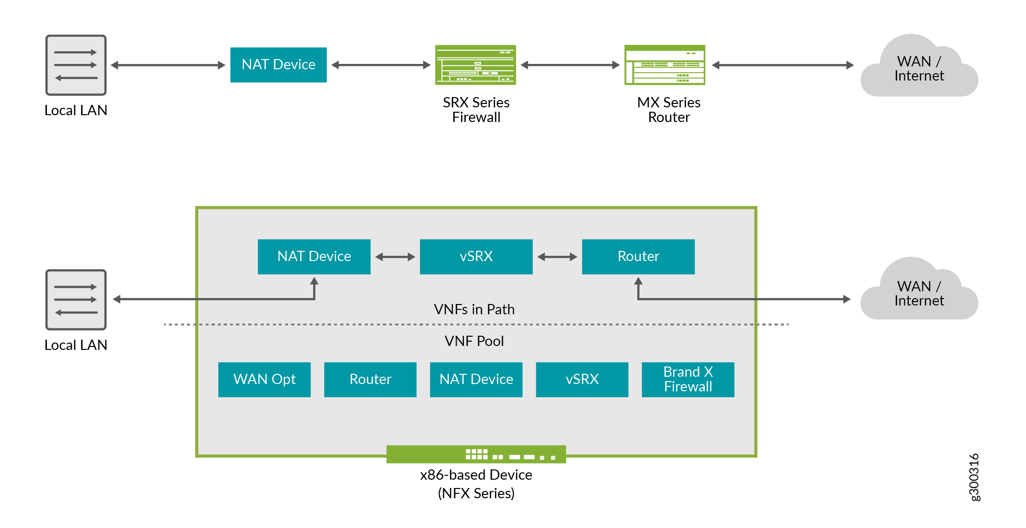
Network Function Virtualization (NFV) is a concept in which network functions traditionally performed by dedicated hardware devices are performed by software that runs on virtual machines in various network locations. The virtual machines run software that performs traditional functions like routing, firewall, or network address translation (NAT). These functions are known as virtual network functions (VNFs). In Figure 1, the upper part of the diagram shows conventional physical network devices chained together to provide network services. The lower part of the diagram shows how the same service chain can be created from a pool of VNFs available on an NFX Series device.
Juniper’s CSO solutions comply with European Telecommunications Standards Institute (ETSI) standards for lifecycle management of network service instances.
The Contrail SD-WAN Solution uses the following components for the Network Functions Virtualization (NFV) environment:
For SD-WAN deployments:
The Network Service Orchestrator, together with the Network Service Controller, provides ETSI-compliant management of the life cycle of network service instances.
The Network Service Controller provides service-chaining and the VIM.
The CPE device provides the NFV infrastructure (NFVI).
Other CSO components connect to the Network Service Orchestrator through its REST API:
Administration Portal, which you use to set up and manage your virtual network and customers through a graphical user interface (GUI).
Administration Portal offers role-based access control for administrators and operators. Administrators can make changes; however, operators can only view the portal.
Customer Portal, a GUI that your customers use to manage sites, CPE devices, and network services for their organizations.
Customer Portal offers role-based access control for administrators and operators. Administrators can make changes; however, operators can only view the portal.
Designer Tools:
Configuration Designer, which you use to create configuration templates for virtualized network functions (VNFs). When you publish a configuration template, it is available for use in Resource Designer.
Resource Designer, which you use to create VNF packages. A VNF package consists of a configuration template and specifications for resources. You use configuration templates that you create with Configuration Designer to design VNF packages. When you publish a VNF package, it is available for use in Network Service Designer.
Network Service Designer, which you use to create a network service package. The package offers a specified performance and provides one or more specific network functions, such as a firewall or NAT, through one or more specific VNFs.
In Administration and Customer Portals, you can add configuration templates only for Juniper Networks devices. In Configuration Designer, you can create configuration templates for both Juniper and non-Juniper devices.
CSO solutions extend the NFV model through the support of physical network elements (PNEs). A PNE is a networking device in the deployment that you can configure through CSO, but not use in a service chain. Configuration of the PNE through CSO as opposed to other software, such as Contrail or Junos OS, simplifies provisioning of the physical device through automation. Combining provisioning and configuration for PNEs and VNFs provides end-to-end automation in network configuration workflows. An example of a PNE is a vSRX device serving as a provider hub for the termination of IPsec and GRE data tunnels.
OSS/BSS applications and CSO components with OSS/BSS capabilities send requests to Network Service Orchestrator through its northbound REST API. Network Service Orchestrator then communicates through its southbound API to the northbound API of the appropriate, directly connected, component. Subsequently, each component in the deployment communicates through its southbound API to the northbound API of the next component in the hierarchy. Components send responses in the reverse direction.