Add IP VPN Configuration to Provider Hubs
You can configure IP VPN (Layer 3) parameters to connect an existing Layer 3 VPN which is not managed by Contrail Service Orchestration (CSO) to a network managed by CSO through a provisioned provider hub site.
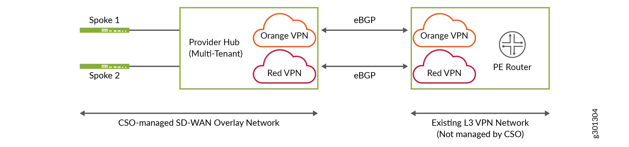
Figure 1 shows a sample network topology with IP VPN interconnect. On the left side, a CSO-managed SD-WAN overlay network is shown consisting of a multi-tenant provider hub which can be connected to multiple spoke sites or enterprise hub sites belonging to different tenants. On the right side, an existing L3 VPN network which is not managed by CSO is shown. The PE router interconnects with the provider hub to create an IP VPN. Two department VPNs, orange and red, connects the provider hub and the PE router using point-to-point external BGP (eBGP) peering. This peering is implemented using Inter-AS Option-A. For more information, see Interprovider VPNs.
IP VPN can be configured only for provisioned provider hub sites with OAM_AND_DATA or DATA_ONLY capability for each tenant department VPN.
IP VPN configuration is not applicable for data center department VPNs.
Starting in Release 6.1.0, CSO explicitly disables the long-lived graceful restart (LLGR) capability for BGP peering sessions with provider edge (PE) and data center or LAN routers. Disabling LLGR ensures that the CPE does not differentiate the route advertisements to the peering router irrespective of the peering router’s LLGR capability.
Prior to CSO Release 6.1.0, LLGR helper mode is enabled by default (implicit behavior of Junos OS) on the CPE for BGP peering towards the PE router in IP VPN deployments, and data center or LAN routers in data center deployments.
To add an IP VPN configuration:
Field |
Description |
|---|---|
Interface Name |
Enter the name of the physical interface on which you want to enable external BGP (eBGP) between provider hub site and the PE router. For example, ge-0/0/10. |
VLAN ID |
Enter the VLAN ID of the interface. Range: 1 through 4094. |
Interface IP Prefix |
Enter IPv4 address with a prefix for the interface. For example, 10.10.10.1/24. |
AS Loop Count |
Enter the maximum number of times the detection of local Autonomous System (AS) number is allowed in the AS path. If this count exceeds the specified AS loop count, the system discards this route. This helps in preventing routing loops. For example, if you configure AS Loop Count as 1, the route is discarded if the neighbor’s local AS is detected in the path more than once. Range: 1 through 10. |
eBGP Peer-AS-Number |
Enter the autonomous system (AS) number for the eBGP peer. Range: 1 through 4294967295. |
Neighbor Address |
Enter the IPv4 address of the peer interface. |
Local AS number |
Enter the local AS number for the IP VPN configuration. When you configure this parameter, the local AS number is used for eBGP peering instead of the global AS number configured for the provider hub. |
Authentication |
Select one of the following BGP route authentication method:
|
Disable Graceful Restart |
Disable graceful restart configuration for the provider hub by clicking the toggle button while trying to peer with a device which does not have the graceful restart capability. By default, graceful restart helper mode, the ability to assist a neighboring router attempting a graceful restart, is enabled. |