Multi-Service Shared Bearer Overview
Contrail Service Orchestration (CSO) supports the provisioning of more than one service on the same physical (bearer) interface for WAN links associated with on-premise SD-WAN spoke sites and enterprise hub sites. In previous CSO releases, each WAN link had to be configured as a separate physical interface. However, from CSO Release 5.1.0 (for on-premise spoke sites) and CSO Release 5.1.1 (for enterprise hub sites), WAN links can be configured as logical interfaces on the same physical interface. Therefore, the same physical interface can be used to carry Internet and MPLS traffic with VLAN separation. The shared bearer (physical interface) supports both full-mesh and hub-and-spoke topologies.
Figure 1 shows an example of a shared bearer topology. There are two WAN links on the CPE device (WAN 0 and WAN 1), which are connected to two PE devices, one on an MPLS network and the other on an Internet network.
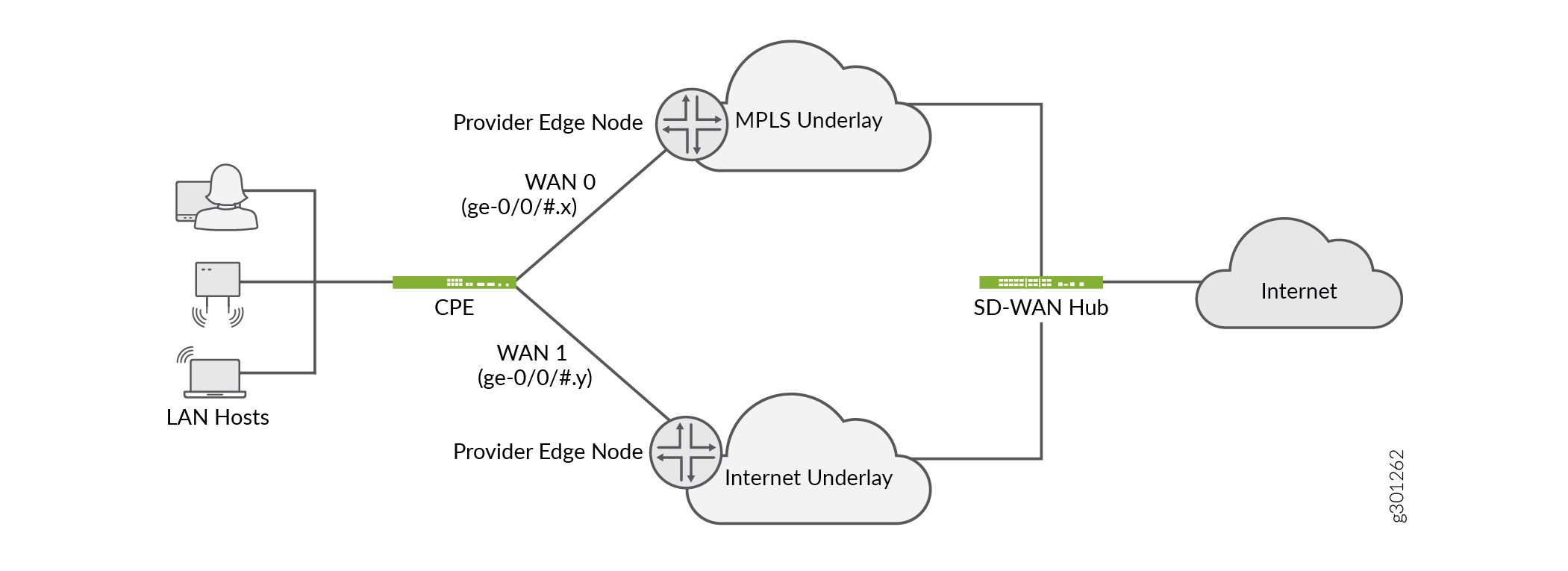
In this example, WAN 0 uses the logical interface ge-0/0/#.x, and WAN 1 uses the logical interface ge-0/0/#.y.
Here, ge-0/0/# represents the physical interface, where # represents the port, and x and y represent the logical unit numbers of the physical interface ge-0/0/#. For example, if the physical interface is ge-0/0/3, then the logical interfaces can be ge-0/0/3.10 and ge-0/0/3.11.
Therefore, WAN 0 and WAN 1 share the same physical interface, but are on two separate logical interfaces with VLAN separation.
The interface names might differ based on the device model and the WAN interface configured in the device template.
When the same physical interface is used for multiple WAN links:
CSO supports class of service (CoS) provisioning of the shaping rate at the logical interface level. In previous releases, CoS provisioning of the shaping rate was supported only at the physical interface level. Shaping rate controls the maximum rate at which traffic is allowed to be transmitted on an interface.
CSO supports flexible (mixed) tagging with simultaneous tagged and untagged WAN links for single CPE devices. However, when there are multiple logical interfaces on the same physical interface, there can be only one untagged logical interface and the rest of the interfaces must be tagged. The support for simultaneous tagged and untagged logical interfaces on same physical interface is not available on dual CPE devices. Table 1 displays the VLAN tagging support for single and dual CPE devices.
To enable the configuration of WAN links as logical interfaces in enterprise hub and on-premise SD-WAN spoke sites, the administrator users must modify the device template and configure the WAN ports as logical interfaces. See Configuring Template Settings in a Device Template.
Type of CPE |
VLAN Tag |
Unique Physical Interface for Each WAN Link |
Same Physical Interface for More Than One WAN Link |
|---|---|---|---|
Single CPE |
Untagged |
Supported |
Supported. However, only one WAN link can be untagged. |
Single CPE |
Tagged |
Supported |
Supported |
Dual CPE |
Untagged |
Supported |
Not supported |
Dual CPE |
Tagged |
Supported |
Supported |