Device Redundancy Support Overview
Contrail Service Orchestration (CSO) supports spoke redundancy for large enterprise SD-WAN branch sites. To protect an SD-WAN site against device or link failures, you can configure the site with two CPE devices that can function as primary and secondary devices. If the primary device fails, the secondary device takes over the traffic processing.
You must use the same device model for both primary and secondary devices and the devices must have the same version of Junos OS installed.
The following SD-WAN features are not supported for device redundancy:
-
LTE WAN backup link
-
Service chaining
Device redundancy is supported only for SD-WAN deployments.
Prerequisites for using SRX Series Devices for Device Redundancy
The prerequisites to configure an SD-WAN site with dual CPE SRX Series devices are as follows:
-
For SRX Series, you need to form the cluster manually by connecting two SRX Series devices together using a pair of the same type of Ethernet connections. To create an SRX cluster, see Chassis Cluster Feature Guide for SRX Series Devices.
-
Log in to any one of the SRX Series devices, copy the Stage-1 configuration from the Sites page and paste it into the console screen and commit the configuration.
Supported Connection Plans
The following connection plans are supported for device redundancy:
-
Dual NFX250 as SD-WAN CPEs—Supports NFX Series devices as CPE devices in an SD-WAN site.
-
Dual SRX as SD-WAN CPEs—Supports SRX Series devices and vSRX as dual CPE devices in an SD-WAN site. Ensure that the CLUSTER_OFFSET value is set as 7. You cannot use ge-0/0/0 as a WAN interface as it is used as the control port in a vSRX cluster.
-
Dual SRX4x00 as SD-WAN CPEs—Supports SRX 4100 and SRX4200 devices as dual CPE devices in an SD-WAN site.
Create and Configure an SD-WAN Site
You can create and configure an SD-WAN site with dual CPE devices and the two devices back up each other, with one node acting as the primary device and the other as the secondary device. The workflow to add and configure a site with dual CPE devices is similar to the single CPE device. For more information about creating and configuring a site with dual CPE devices, see Creating On-Premise Sites, Managing a Single Site, and Edit Branch and Enterprise Hub Site Parameters.
Dual CPE Devices Logical Topology for NFX Network Services Platform
Figure 1 shows the logical topology of the NFX Series dual CPE devices.
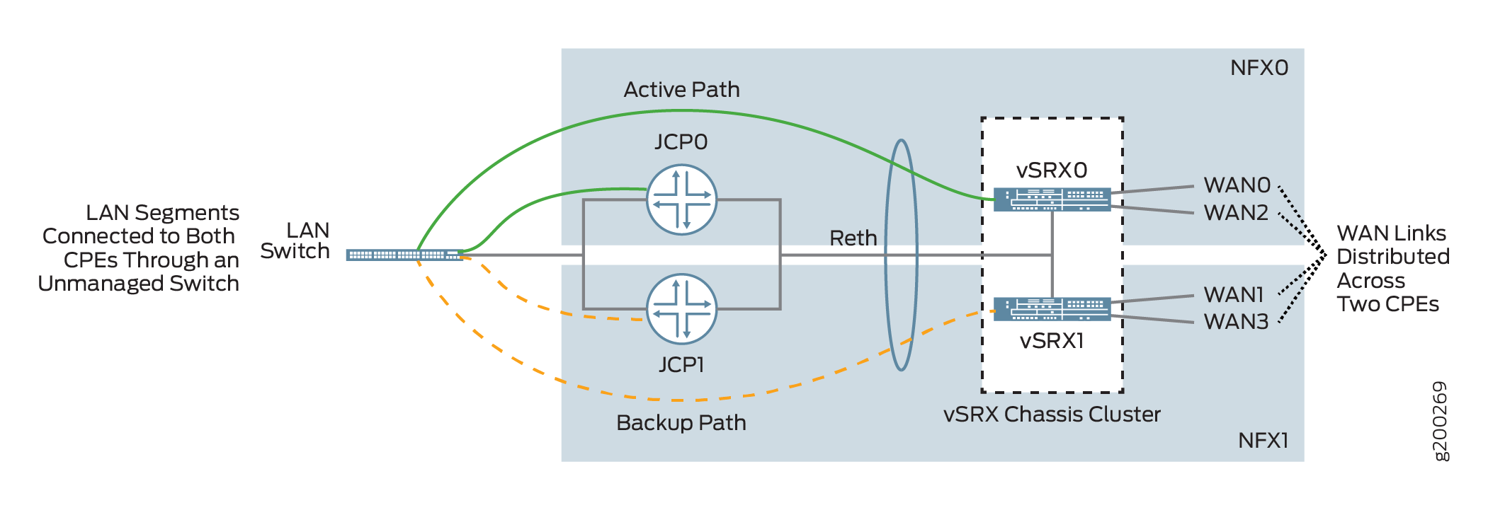
You can form a cluster using two NFX Series devices. The front panel ports of the NFX Series devices are used to interconnect two NFX Series devices and to carry the control and fabric interconnect traffic between the two NFX250 devices.
The Junos Control Plane (JCP) component acts as a switch, controls the front panel ports, and sends the traffic which arrives from the LAN or WAN to the NFX Series devices. On the LAN, the active/backup mechanism is used and if the primary device fails, the secondary device takes over processing of traffic. On the WAN, the active/active mechanism is used and all four WAN links are active and distributed across two NFX Series devices.
Dual CPE Devices Logical Topology for SRX Series Gateway Devices
Figure 2 shows the logical topology of the SRX Series dual CPE devices.
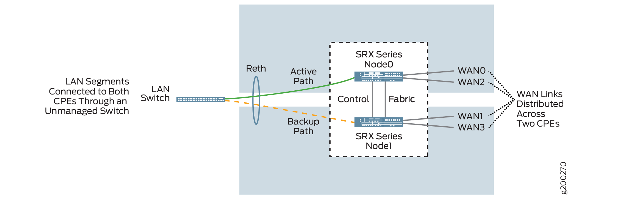
You can form a cluster using two SRX devices. A chassis cluster is formed between these nodes and performs as a single logical router. On the LAN, the active/backup mechanism is used and if the primary device fails, the secondary device takes over traffic processing. On the WAN, the active/active mechanism is used and all four WAN links are active and distributed across two SRX Series device.
On SRX 4100 and SRX4200 devices, out of the eight 1-Gigabit Ethernet/10-Gigabit Ethernet, a maximum of two ports are used for WAN links, and the remaining ports are used for LAN connectivity. The HA ports are used only for forming the cluster.
Dual CPE Support for vSRX
Starting in Release 6.2.0, CSO supports deployment of a vSRX chassis cluster as a spoke. You can create a cluster using two vSRX instances, which are installed in a KVM or an ESXi environment. The control and fabric virtual interfaces on the respective nodes must be connected through a vSwitch or bridge to form a cluster. For more information about configuring a vSRX chassis cluster, see Configure a vSRX Chassis Cluster in Junos OS.
Before enabling chassis cluster on vSRX instances, ensure that both instances have the same software version and licenses installed.
The vSRX cluster operates in the same way as the SRX cluster as shown in Figure 2. On the LAN, the active/backup mechanism is used and if the primary device fails, the secondary device takes over traffic processing. On the WAN, the active/active mechanism is used and all four WAN links are active and distributed across the two vSRX instances.