Platform Characteristics
Multitenancy with RBAC
The CSO platform has built-in multitenancy support, enabling multiple tenants to coexist on the system. Multitenancy is based on the OpenStack Keystone model. In this model, each object in the database belongs to a specific tenant and is assigned a tenant ID. When an administrator is granted certain roles to a specific tenant, he or she is authorized with certain rights to all objects belonging to that tenant.
The server enforces multitenancy RBAC at the API level. A user must authenticate with CSO’s Identity and Access Management (IAM) microservice to acquire the access token first before any CSO APIs can be invoked. On each API call, the API server enforces the multitenancy RBAC by making sure the object’s tenant ID matches the assigned tenant IDs in the access token, and the REST URI is defined in the assigned roles.
RBAC in CSO is object-based. To simplify RBAC application, CSO has pre-defined user roles which provide users assigned to those roles read-only or read-and-write access to specific objects. Custom roles allow administrators to grant users additional access privileges to those or other specific objects.
High Availability and Scale
As noted above, the CSO installation architecture for small environments does not provide HA. The small setup includes one instance each of a central VM and a regional VM; any VM failure renders CSO non-operational. CSO can also scale out for larger environments, using multiple servers with load balancing between them. These servers typically work in active/active HA mode, and services are duplicated across servers. The loss of a server does not impact CSO functionality.
A key design principle is that there is no in-memory state. All the states are transactional and maintained in a database using a Job Manager. CSO ensures that if a node fails, the Job Manager automatically detects the incomplete job and assigns the process to an alternate server for processing.
All CSO infrastructure services, such as database services and message buses, use proven open source software that supports multi-node clustering for HA and scale. These infrastructure service clusters are fine tuned for large scale deployment. The primary CSO configuration and analytics database is built on Cassandra, which is known for its scalability and fault tolerance on commodity hardware and in cloud environments.
All CSO microservices are stateless and do not hold any state between API calls. The application states are kept in the database. Microservices communicate with each other only through RESTful APIs or the highly available message bus. Microservice RESTful APIs are designed to be idempotent (making the same call repeatedly produces the same result) and highly fault tolerant over commodity hardware or cloud environments. CSO microservices are packaged as Docker containers and orchestrated by Kubernetes. Because of the stateless nature and idempotent APIs, each microservice can scale linearly and independently. Kubernetes allows each microservice to scale up and down automatically based on CPU usage. Kubernetes can also monitor the health of CSO microservice instances, and auto-heal failed instances.
The CSO platform can be deployed on-premises, or in a hybrid or public cloud infrastructure. When deployed across multiple availability zones of the public or private cloud, the platform can survive power and network failures across centers.
Programmability and Integration
All CSO microservices make their functionality accessible via RESTful APIs. Some of these APIs are meant for consumption by other microservices or applications running on CSO, but most are exposed to be consumed by external systems, such as northbound OSS/BSS applications. This allows providers and end customers to automate various tasks, processes, and workflows by invoking these APIs from scripts or backend systems. All microservice APIs are generated from data model descriptions in YANG and can be categorized at a high level as:
CRUD APIs to create, read, update, and delete resources in the system. These are synchronous APIs that return status and details using HTTP. The caller can define a tenant topology, add or delete sites to this topology, enable no-touch activation of devices at the customer site, setup network connections defined in the topology, enable end user configuration of on-premises devices, monitor device and link status, and more.
RPC (Remote Procedure Call) APIs to perform operations on these resources. These are typically asynchronous APIs that return completion status and results using Advanced Message Queuing Protocol (AMQP) notifications. The caller can specify an exchange and a routing key for the response message, and the CSO microservice will publish the result notification to that exchange using the specified routing key.
CSO microservices also publish various messages to certain documented exchanges created in the AMQP server, including various resource state change events and alerts. External systems can consume these messages and perform various tasks, thus allowing them to create event-driven automation tasks. One can configure new rules in the FMPM microservice to generate specific alerts and also post alerts on different message buses like Kafka.
The APIs exposed by CSO can be categorized as shown in Table 1.
Catalog management |
APIs to manage network service descriptors and VNFs |
VIM/POP Management |
APIs to create define and manage VIM and POP data centers |
Topology Management |
API to insert and manage end-to-end CPE service topology (logical) |
Site/Customer Creation |
APIs to manage customer/site objects and association with service topology nodes. |
Network Design APIs |
APIs to define virtualized services and service chains |
Site Activation |
APIs to notify vCPE/uCPE device deployment, topology and service placement. |
Identity Management |
APIs to manage Identity for both enterprise and service provider users |
Bootstrap Service |
APIs for configuration and management device activation service |
Service Placement/Instantiation |
APIs to position and manage service chains in customer topology |
Device and Service Monitoring |
APIs to monitor status of devices, network services, and services topology |
Root Cause Analysis/Troubleshooting |
APIs trace and correlation engine for events, alarms and logs |
Zero touch and Device Management |
APIs for activating, provisioning and managing NFX/SRX |
Image Management |
APIs to manage NFX, SRX, EX, and EX VC software images |
SD-WAN |
APIs for link provisioning, auto-VPN, discover-VPN, distributed routing |
Abstracted Routing |
APIs for creating L2/L3 service chains |
Public Key Infrastructure (PKI) |
APIs for working the PKI security features |
For detailed list of APIs, see Contrail Service Orchestration API Reference.
Extensibility and Customization
CSO is architected to allow easy extension and customization of its microservices. These capabilities can be categorized into three main building blocks:
Plugin-based architecture: Various microservices, such as EMS, FMPM, VNFM, Flex, etc., have a plugin-based architecture to allow their behavior to be extended and customized using plugins that can be created and installed without requiring any code changes in the microservice itself. These microservices ship with a certain set of plugins, and new plugins can be created and added in the field.
Customization of site connectivity topology and activation workflows: For every site, the WAN-side connection topology, as well as the configuration deployed to the on-premises device(s) during its activation are modeled as device templates. These templates can be modified, or new ones created, in the field to customize the activation workflows and configurations based on each service provider’s unique requirements.
Telemetry and Analytics Capability
An important capability of the CSO platform is its ability to collect telemetry data from different devices/VNFs and use it to:
Store as time series data and make the data query-able from Northbound Applications and the CSO UI to display as charts and graphs.
Create events for microservices to be able to react to. For example, SLA metrics collected from the devices are published to analyze for link SLA violations, so that the relevant applications can take the appropriate action.
Publish selected data to Northbound listening applications over Kafka and RabbitMQ.
CSO uses Contrail Analytics nodes to store time series data. Contrail Analytics by itself is a horizontally scalable component that provides high availability as well as the ability to query data through REST APIs. The data from the time series is exposed through CSO APIs to the UI and Northbound applications.
Intent-Based Policies
CSO’s user interface puts a strong focus on simplifying and automating many of the main functions an operator needs to perform. This simplification is enabled by modeling enterprise objects and using intent-based policies to configure them.
Intent-based policies allow an operator to configure policies using constructs such as departments, sites, site groups, and application groups. The policy is applied to all relevant devices that match the parameters specified in the matching construct; the operator does not have to worry about configuring the policy explicitly on the devices.
Intents can be expressed as part of various workflows, as described below:
Site Onboarding–During site or hub onboarding, the following intents can be specified:
Default link - tenant admin can choose a default link; used as the default overlay path for all traffic which doesn’t have a policy saying otherwise.
Application breakout - enables site administrators to designate that certain application traffic be routed directly to the Internet from the spoke site.
Central breakout - enables Internet-destined traffic to break out directly to the Internet at the enterprise hub.
Department breakout - enables site administrators to designate that all Internet-destined traffic from a specific local department be routed directly to the Internet from the spoke site.
Hub breakout - enables site administrators to designate that all Internet-destined traffic be route directly to the Internet from the provider hub device.
Site group - allows the same policies to be deployed across a group of sites with similar characteristics.
Site local Internet breakout - enables site administrators to designate that all Internet-destined traffic be routed directly to the Internet from the spoke site.
Zscaler breakout - Allow all Internet-destined traffic to be routed to a Zscaler implementation prior to going to the Internet. This breakout can be done locally, centrally, or at the provider hub.
Note:Although the above intents can be specified during the site onboarding process, they are not applied until after ZTP.
SD-WAN Intent Policy Creation–Steering and breakout profiles can be created to be used in SD-WAN policies.
Two types of profiles are supported:
Path-Based Steering Profile – operator explicitly specifies a preferred path for traffic. Traffic matching an SD-WAN policy using this profile will take the preferred path.
Breakout Profile - operator specifies a breakout type of either, local breakout using underlay networking, backhaul using hub sites for breakout traffic, or local breakout using a cloud-based platform such as Zscaler. The operator also specifies a traffic type profile and preferred path for the breakout traffic. If a WAN link type that matches the preferred path is available at the CPE and enabled for breakout, then the traffic will use that link for breakout traffic. If any is selected as the preferred path, then CSO will use all available links that are enabled for breakout in a load-balancing fashion.
An SD-WAN policy can be created by specifying the following elements:
Source endpoint(s) - site groups, departments
Destination endpoint(s) - application/application groups
Action - Steering profile or breakout profile
The operator simply needs to select these high-level elements from the available drop-down menus, and then deploy the policy. CSO takes care of translating these intents into configurations that are pushed to the relevant network devices.
Security Intent-Based Policies
To create firewall policies, the operator does not need to specify the location and connectivity information of the endpoints; instead, CSO uses existing topology information to determine how the relevant endpoints are connected and creates the appropriate security policies to be deployed to the appropriate policy enforcement points.
Firewall policy intents can be defined using the following elements as source and destination identifiers:
Site
Department (SRX security zone: Up to 25 departments supported starting in CSO version 4.1)
Application (L7: signature based)
Services (protocol based)
Address objects representing hosts, networks, IP ranges, etc.
Firewall intents are order insensitive, meaning the operator does not have to arrange the intents in the proper order. CSO analyzes all firewall intents and converts them to security policies statements in correct order.
Upgrade and Backward Compatibility
CSO supports seamless upgrades from previous versions, including infrastructure services and microservices upgrade, data migration, device connectivity, and configuration.
The upgrade procedure is an ‘offline’ activity; all microservices are shut down while the upgrade is in progress. However, network devices (CPEs, hubs, etc.) and the SD-WAN environment overall continue to function normally.
The CSO data model and APIs maintain backward compatibility such that latest version of all CSO microservices support (read/write) data created by previous versions. Migration scripts/additional workflows can also be executed as part of the upgrade process.
Element Management
CSO includes a set of microservices that provide scalable, multi-vendor element management capabilities. These capabilities are used to provide SD-WAN services by managing, orchestrating, and controlling the physical and virtual networking devices that make up the overall solution.
These devices can generally be brought under CSO management in two ways:
If the device is already provisioned, it can be discovered by CSO and brought under its management by providing the device’s management IP address and admin account credentials. A provider hub device located in a service provider POP is typically discovered using this option.
For devices that need to be automatically brought online and provisioned, CSO employs a zero-touch mechanism to bring the device under its management. By providing the serial number of the expected device at each site, CSO creates a device object in its database corresponding to each device and prepares the image and configuration that needs to be delivered to it. When the device arrives at the site and is racked up and powered on, it will reach out to the Juniper redirect service (https://redirect.juniper.net) to learn how to reach its regional CSO instance. Upon contacting the CSO server, the device receives an assigned software image and initial configuration. Once up and running, CSO performs further actions on the device, such as bringing up required VMs, provisioning overlay tunnels, installing a telemetry agent, etc.
CSO interacts with network devices using NETCONF or CLI sessions over SSH, thus ensuring that all management communications use a secure, encrypted channel. CSO supports both password-based authentication as well as SSH key-based authentication to the device.
Figure 1illustrates the various microservices that work together to provide CSO’s element management capabilities, and how they are distributed across central and regional servers.
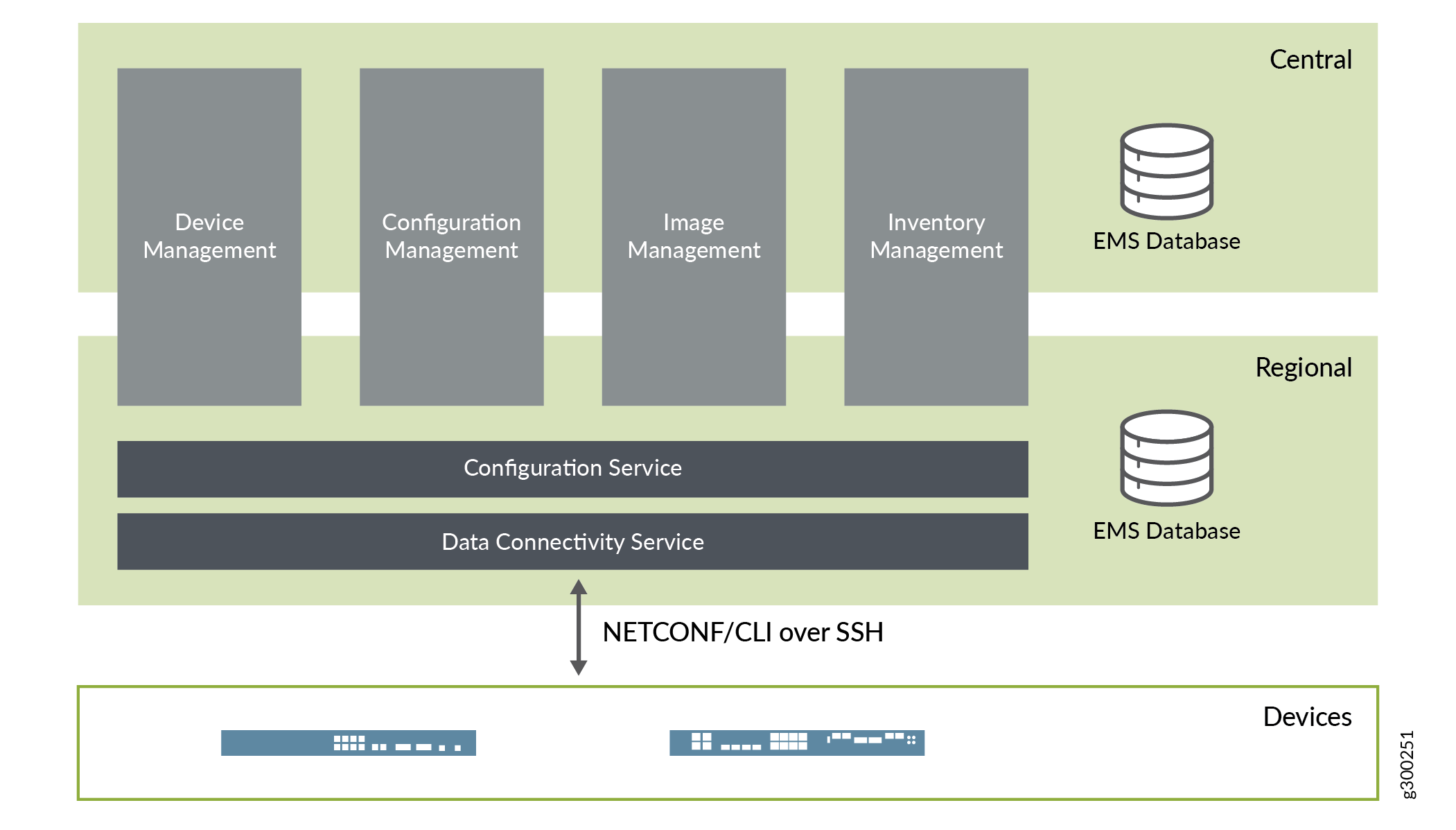
Microservice |
Description |
|---|---|
Activation Service |
Supports secure zero-touch activation of CPE devices through draft-ietf-netconf-zerotouch. |
Device Management Service |
Manages the lifecycle of devices; devices include VNFs, PNFs, CPEs, PEs, IPsec concentrators, etc. |
Config Management Service |
Manages the lifecycle of configuration objects, including their versioning as well as their deployment onto devices. |
Image Management Service |
Maintains a repository of device images and other software packages, and manages the deployment and installation of these onto devices. |
Inventory Service |
Takes care of discovering and managing physical and logical inventory resources on devices. |
Template Service |
Manages all templates on-boarded into the system, and provides APIs for rendering them using different template engines via plugins; templates can be used to generate configuration or operational commands. |
FMPM Provider Service |
Centralized service that maintains all FM and PM data, and provides APIs for collecting and querying the data. |
FMPM Collector Service |
Distributed service that is responsible for collection of FM and PM data from managed entities. |
Config Service |
Provides APIs to execute commands on managed devices, and acts as the gateway between all microservices and managed devices; has a plugin-based architecture to support multiple management protocols, such as NETCONF/SSH, CLI/SSH, and REST/HTTP. |
Device Connectivity Service |
Takes care of transport connection establishment and authentication between CSO and the managed devices. |
CSO Behind NAT
CSO can be installed behind a NAT gateway. When used, managed devices can reach CSO through a publicly exposed IP address. This option is specified during initial CSO installation, and requires some additional manual configuration of NAT rules once setup is complete.
CSO in the Cloud
While CSO is often installed within the service provider’s network, it can also be installed in the cloud, depending on design requirements.
CSO in Public Cloud
Figure 2 shows CSO located in an AWS VPC and accessible through a private connection. This is known as a cloud-hosted CSO deployment. CSOaaS is based on this model.
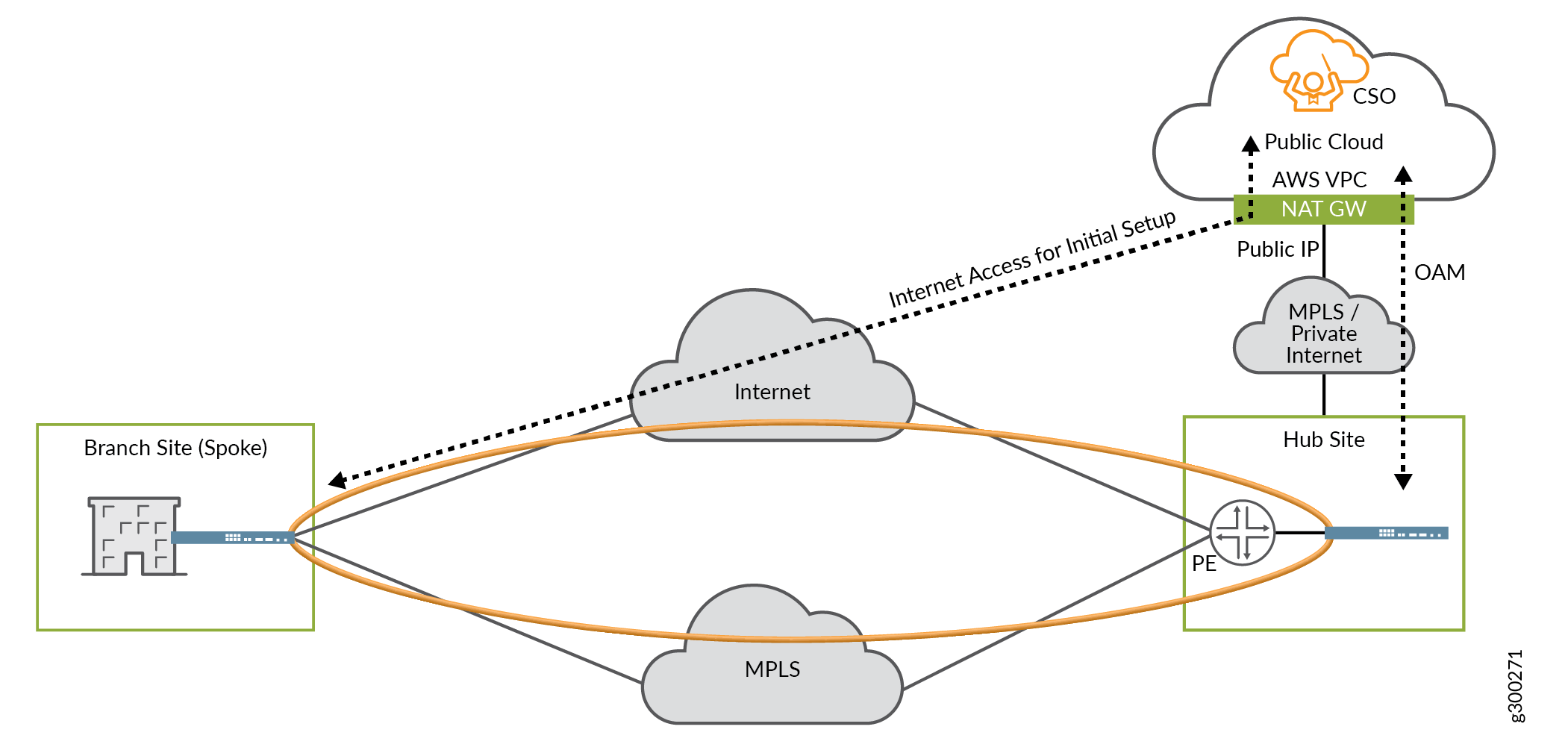
Implementation characteristics:
The CSO installation uses private IP addressing.
The NAT gateway provides a public-facing IP address for CSO.
The connection between CSO and the hub device uses an MPLS network or a private Internet connection, such as AWS Direct Connect.
The hub device must use a public IP address for OAM.
The hub device’s IP address must be directly reachable from CSO.
The spoke device initiates its connection to CSO using the public IP address on the NAT gateway.
CSO on Internet
Figure 3 shows CSO located at some other on-Internet location, such as in a private cloud, and accessible directly over the Internet.
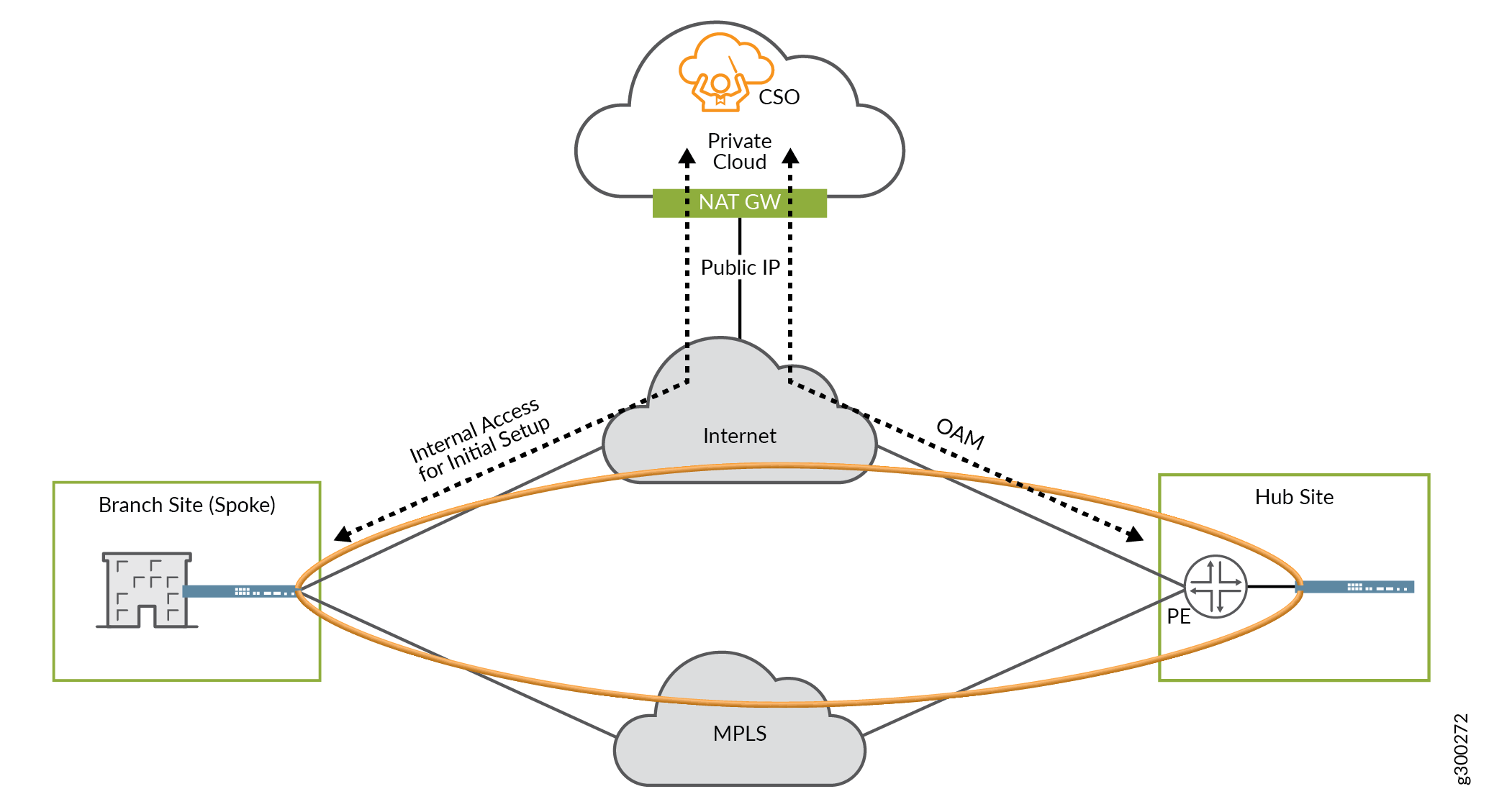
Implementation characteristics:
The CSO installation uses private IP addressing.
The NAT gateway provides a public-facing IP address for CSO.
The connection between CSO and the hub device uses the public Internet.
The hub device must use a public IP address for OAM.
The hub device’s IP address must be directly reachable from CSO.
The spoke device initiates its connection to CSO using the public IP address on the NAT gateway.
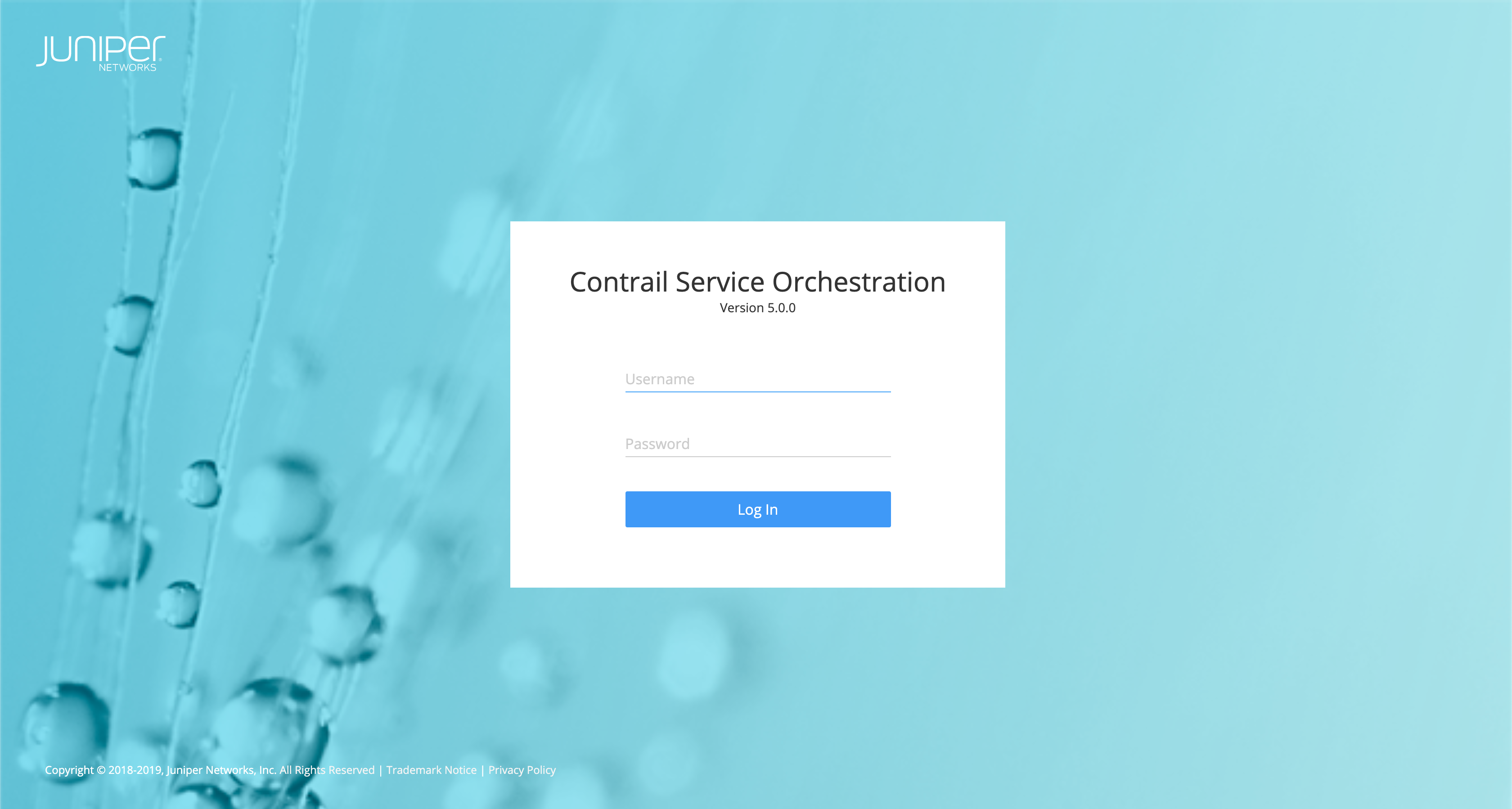
CSO User Interface
CSO software offers a single Web-based UI to create, configure, and monitor tenants, sites, devices, network topologies, and security and SD-WAN policies. A sample screenshot of the dashboard is shown in Figure 4.
Web UI Architecture
The CSO Web UI uses a lightweight framework for building single-pane-of-glass user interfaces in a decoupled way. The UI allows workflows to be dynamically created from independently developed and deployed plugins, which allow the UI to be extended dynamically in a customer environment without any impact on existing functionality.
The UI architecture supports a single, unified dashboard that hosts monitoring widgets. A thumbnail view of the widgets is provided by the framework, and the operator can drag and drop the widgets to compose customized monitoring views. The UI includes a “preferences” API that can be used to read and write UI-related user preferences, such as a preferred sort order or visible subset of columns for a grid instance. These preferences are preserved across user sessions.
Personas
There are two main personas in the Web UI:
Service Provider admin—global access to all operating companies, tenants, and customers; access CSO through the Administration Portal
Tenant admin—customer-specific access; access CSO through the Customer Portal
Operating Companies (OpCos)
CSO Release 4.0 and later supports operating companies (OpCos) in a service provider environment.
In cases where a global service provider is required to have regional business entities to manage customers on a regional basis (for regulatory, billing, or operational reasons), the OpCo construct enables the service provider to extend their CSO platform to enable each regional entity to independently offer SD-WAN services to its own tenants and customers.
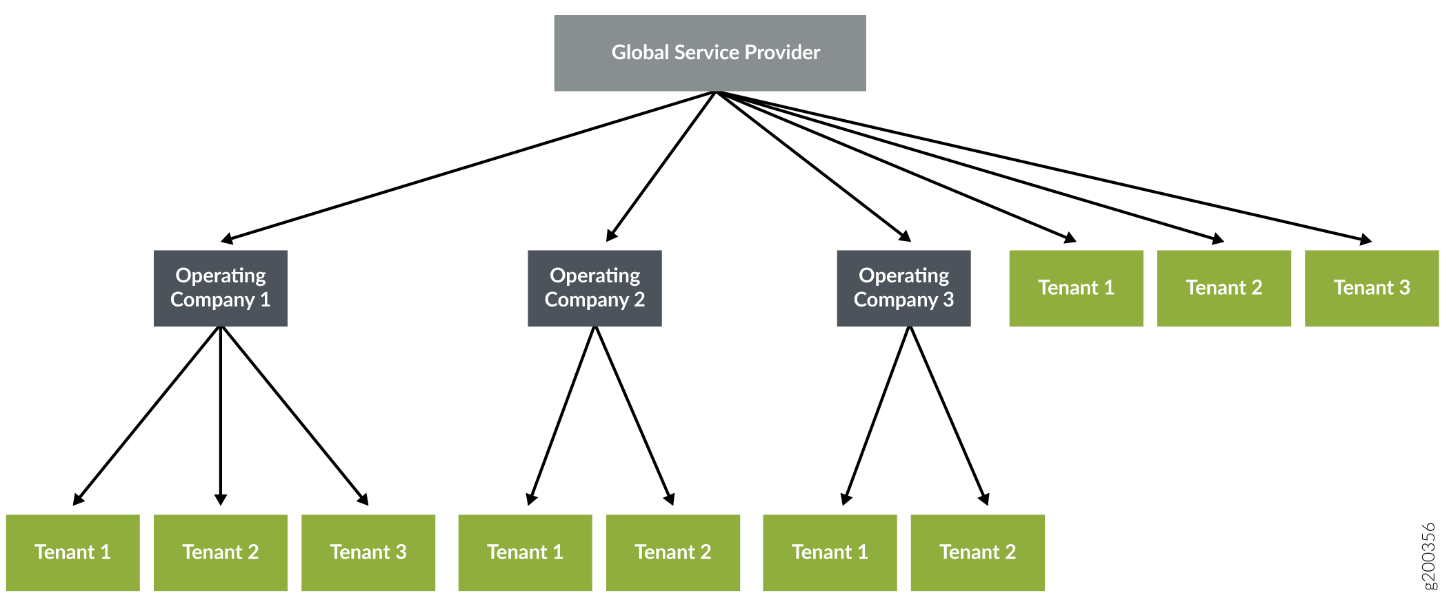
When supporting OpCos, the CSO multitenant hierarchy has three levels:
Global service provider—Contains one or more operating companies and its tenants, manages resources at the service provider level, and shares common resources with operating companies and tenants.
Note:In CSOaaS, there is no user access to the Global Service Provider role/hierarchy.
Operating company—A region-specific service provider that can manage its tenants and provide services to them. Tenants managed by one OpCo are isolated from tenants of another OpCo.
Tenant—Uses the resources provided by the global service provider or OpCo.
Figure 5 shows the relationship between the global service provider, operating companies, and tenants.
For more details on CSO portals, user types, and personas, see the CSO Administration Portal User Guide and CSO Customer Portal User Guide for Release 5.0.
Change History Table
Feature support is determined by the platform and release you are using. Use Feature Explorer to determine if a feature is supported on your platform.