Network Operation
When deploying CSO as an on-premises deployment, it is helpful to know how the network operates and what protocols are in use. When working with a cloud-hosted deployment, the concepts are all the same, but the details and control are invisible to subscribers; they are the responsibility of the team that installs CSO in the cloud.
As with most networks, the Contrail SD-WAN solution generally operates in two planes:
Control plane – OAM and routing traffic
Data (forwarding) plane - user traffic
Control Plane Operation
The control plane for the Contrail SD-WAN solution centers around the CSO platform. More specifically:
CSO’s Network Service Controller (NSC) layer implements the control plane using vRRs.
All sites across all tenants establish MP-IBGP peerings with the vRR.
CSO uses a single private AS number for all tenants, with route targets for tenant separation.
Tenant route separation is provided both by the vRR and by multi-tenant hub devices using BGP extended communities.
vRR Design
All CSO deployments include one or more vRR instances, which provide control plane functionality for the SD-WAN environment. Figure 1 shows a general example where the on-premises devices at each site peer with the vRR.
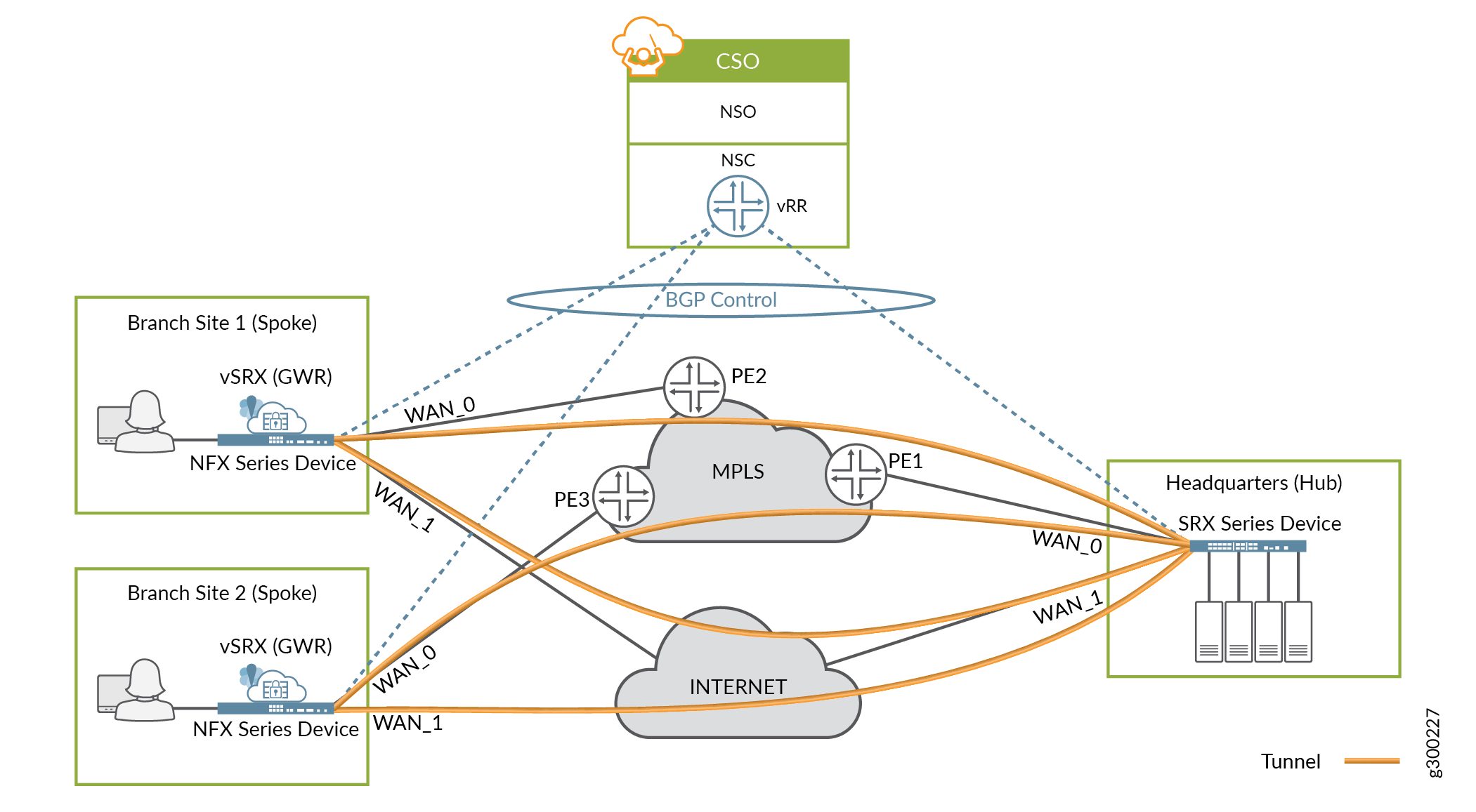
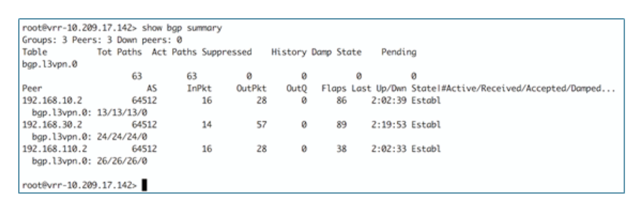
Figure 2 shows an example of the CLI output from the vRR.
Control Plane Resiliency
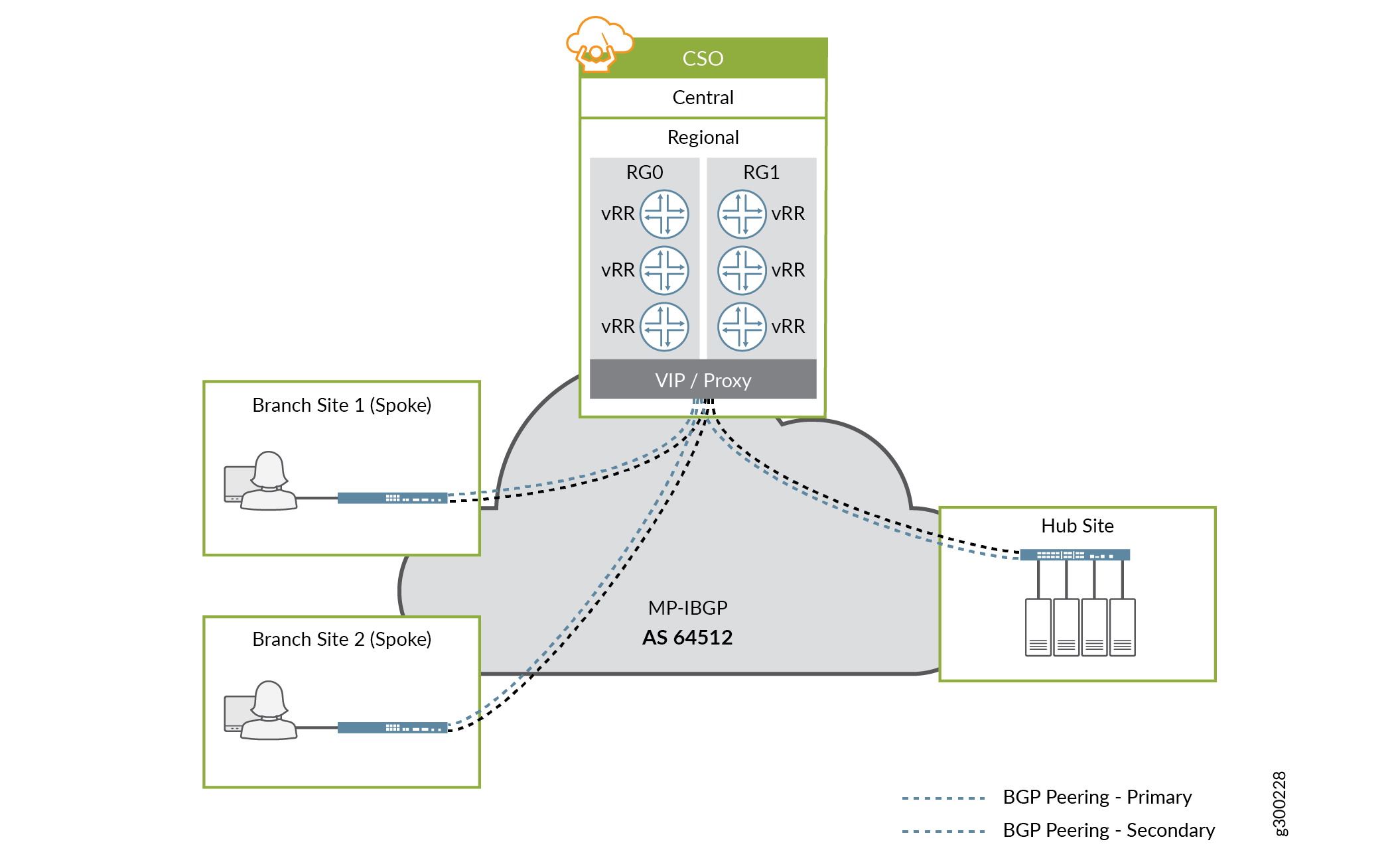
CSO Release 3.3 and later supports the installation of multiple vRRs to provide redundancy and scale. CSO separates the vRRs into two redundancy groups (RGs), and makes a single virtual IP address visible to the network. As part of a site’s configuration, CSO establishes BGP peering sessions between the device and a vRR in each RG. If the primary vRR fails or connectivity is lost, the second vRR continues to receive and advertise LAN routes for the connected sites, thereby providing redundancy. This design is illustrated in Figure 3.
Route Distribution and Separation
The Contrail SD-WAN solution uses Junos OS virtual routing and forwarding (VRF) instances and MP-BGP route targets to provide tenant route separation and enable multi-tenancy.
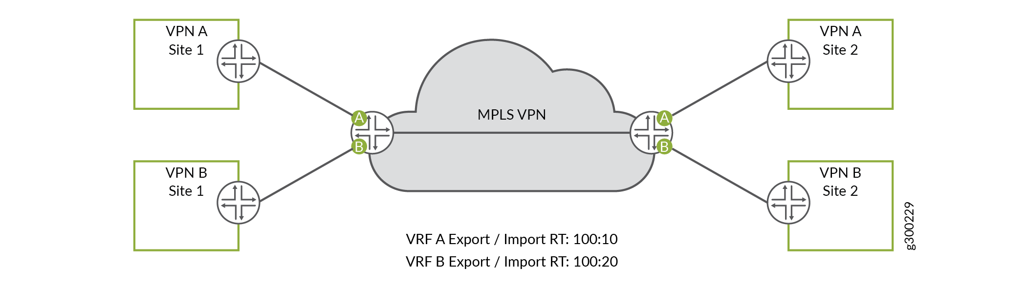
These concepts can be well illustrated using an MPLS VPN environment as an example. As shown in Figure 4, each customer is assigned a unique route target value, and all sites of the customer VPN use that route target value. When a router advertises a customer’s routing information it attaches the appropriate route target value based on which customer VRF originated the advertisements. The receiving router uses the attached route target value to identify the customer VRF into which the received routing information should be placed.
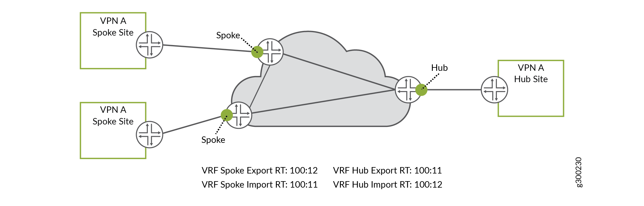
An MPLS VPN hub-and-spoke environment uses route targets differently, as shown in Figure 5. For each customer, every spoke VRF attaches the same route target value when sending routing information. The receiving router accepts routes with that same route target value and installs them into hub VRF. By contrast, the hub VRF attaches a different route target value when sending routing information, and the receiving routers accept and install routes with that same route target value into spoke VRFs.
With this setup, only the hub VRF accepts routes from the spoke VRFs, and only the spoke VRFs accept routes from the hub VRF. Using this method, the spoke sites need very little routing information (perhaps just a default route) as they only need reachability to the hub site, thereby keeping routing tables small and churn-free.
The hub and spoke example above serves as a good foundation, as the Contrail SD-WAN solution implements route distribution and separation in the same way when forwarding traffic from one site to another, or when breaking out traffic to the local internet.
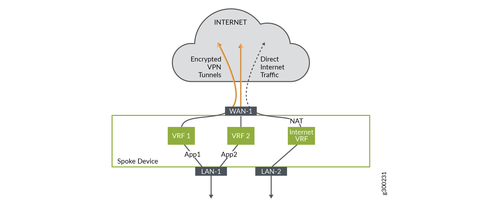
Figure 6 shows a spoke site example where the spoke device is configured with two overlay tunnels and local breakout, with all traffic flowing out the same interface. Each traffic path has its own VRF, and route targets are assigned appropriately at the spoke and hub sites to ensure proper tenant route separation.
APBR and SLA Management - Control Plane
Advanced policy-based routing (APBR) enables you to define routing behavior and path selection per application (group). The APBR mechanism classifies sessions based on well-known applications and user-defined application signatures and uses policy intents to identify the best possible route for the application. Dynamic application-based routing makes it possible to define policies that will switch WAN links on the fly based on the application's defined SLA parameters.
Real-Time Optimized - AppQoE
Starting with Release 3.3.1, CSO supports Application Quality of Experience (AppQoE), a data plane-level mechanism that provides better scalability and faster decision making. Working in conjunction with APBR, AppQoE functions at the device level; that is, the devices themselves perform SLA measurements across the available WAN links, and then dynamically map the application traffic to the path that best serves the application’s SLA requirement. This is all done without the need for the CSO controller to distribute SLA-specific routes.
With AppQoE, when an SLA violation occurs, only traffic corresponding to the application that reported the SLA violation is moved to an alternate link; any other traffic using the link is unaffected.
With real-time optimized SLA management only the default VRF is required, as shown in Figure 7. The default VRF uses ECMP across all the links. The next hop selection per SLA happens in the data path (described in the data-plane section).
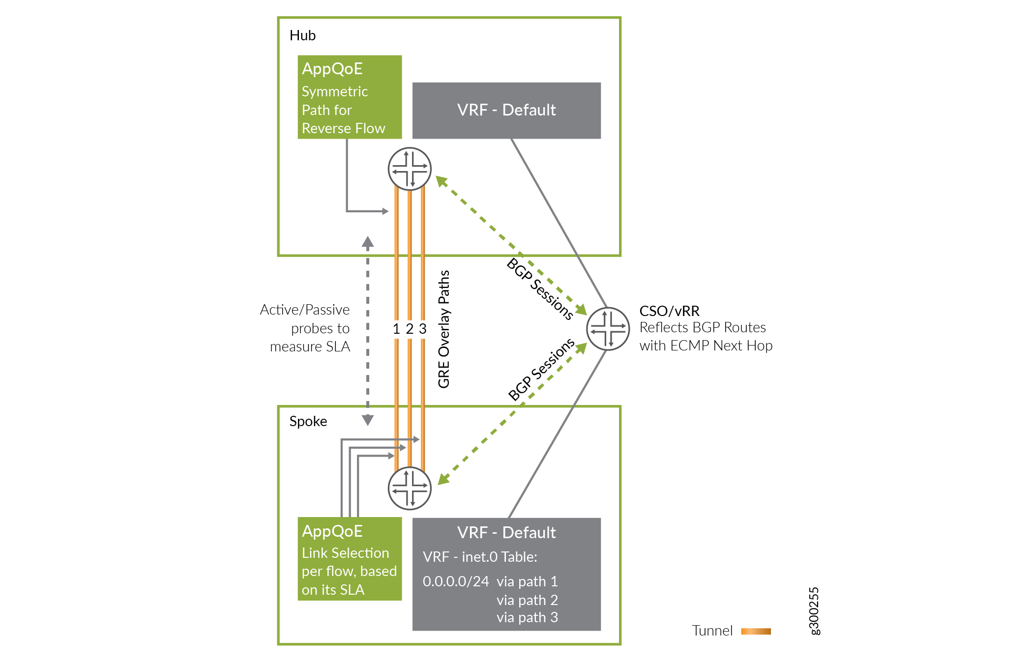
In this case, the MPLS label is used only to identify the tenant.
AppQoE is enabled when the SD-WAN mode for the tenant is set to Real-time Optimized. This is the default mode for SD-WAN deployments.
Note the following about AppQoE:
Only supported on SRX and vSRX Virtual Firewall devices.
Both ends must use the same Junos OS version and the same configuration.
Multi-homing is supported.
Data Plane Operation
This section discusses how a packet is forwarded in a hub-and-spoke topology.
When a user at a spoke site sends traffic through the on-premises CPE device, and the packet is not locally switched or sent direct to the Internet, it is sent over a tunnel to the hub device. This packet from the customer LAN is first encapsulated inside an MPLSoGRE header with the GRE destination as one of the WAN links of the hub device. The MPLS label in the MPLSoGRE header identifies the VRF to be used for forwarding the packet at the hub site. The resulting packet header is shown in Figure 8.

If the tunnel between the spoke and hub site is configured to use IPsec, the MPLSoGRE packet is then further encrypted and encapsulated in an IPsec header that uses tunnel mode. The resulting packet header is shown in Figure 9.

At the hub, the IPsec header is first decrypted. The resulting packet’s MPLSoGRE header is used to terminate the GRE tunnel and perform a lookup in the appropriate VRF, as identified using the MPLS label. Based on the route lookup in the VRF, the packet is then either forwarded towards another spoke site, or out of the SD-WAN environment. If forwarded to another spoke, the hub device encapsulates the packet as described as above.
Design Options
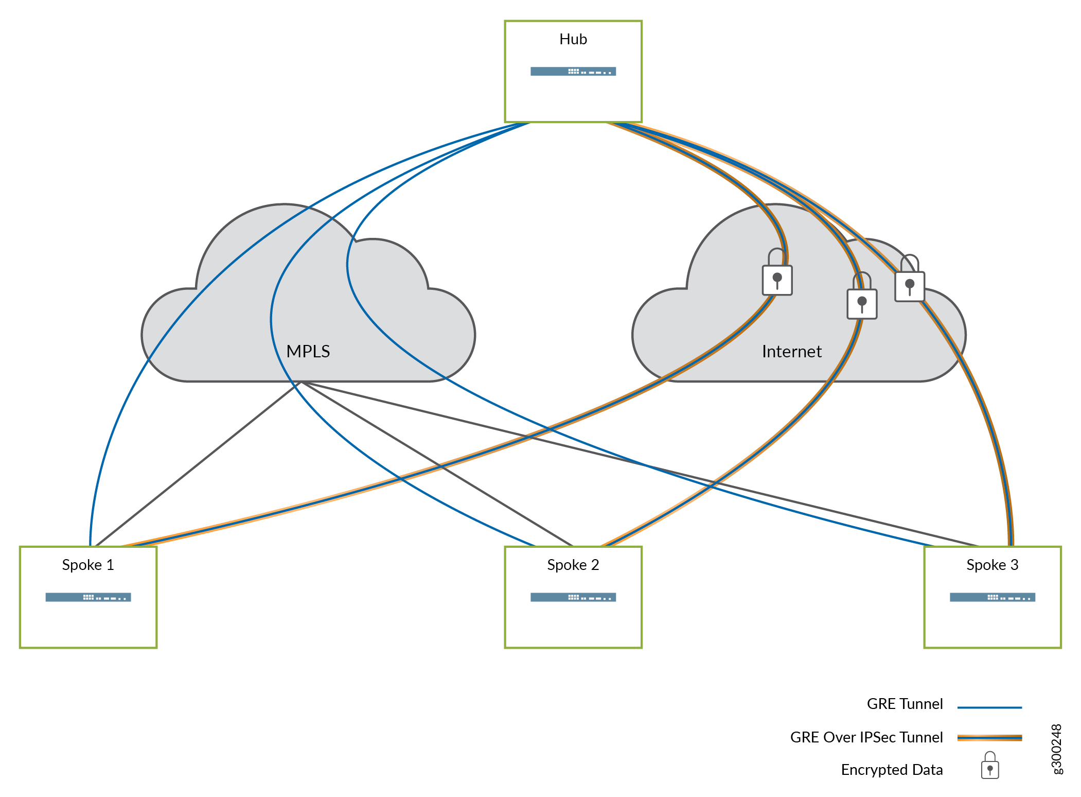
Figure 10 illustrates how the tunnels are typically deployed using the packet headers described above. GREoIPSec tunnels are generally used over the Internet path, given the need for secure packet transport over the public network. GRE tunnels are generally used over MPLS paths, though the GREoIPSec option may also be used as appropriate.
APBR and SLA Management - Data Plane
As noted earlier, tenants can choose one SD-WAN mode of SLA management for application traffic:
Real-time optimized – Device-level SLA management, using AppQoE
AppQoE is a data plane-level mechanism that provides better scalability and faster decision making. With AppQoE, link switching occurs at the application level in the data path of the devices; the devices themselves perform SLA measurements across the available WAN links, without the need of the CSO controller.
Link monitoring occurs using two types of inline probes:
Passive Probes
Inline probes that ride along with application traffic
Mimic the burstiness of the application flows
Enable monitoring of RTT, jitter, packet loss for the application session
Used to monitor currently used path for SLA compliance, detect SLA violation
Active Probes
Periodic probes (based on configuration) that gather SLA data on all potential paths
Used to determine the original best path for the traffic
Used to monitor alternate paths
AppQoE is enabled when the SD-WAN mode for the tenant is set to Real-time Optimized.
Tunnel Liveliness
To avoid blackholing traffic, appropriate liveness checks are enforced in the overlay network. The Contrail SD-WAN solution uses two mechanisms to ensure liveness:
IPsec dead peer detection (DPD), where it is used
GRE keepalives
Mesh Tags and Dynamic Mesh VPNs
As mentioned in the deployment models discussion, dynamic mesh is Juniper’s resource-saving implementation of full-mesh VPNs within CSO. This section describes the operation of mesh tags and dynamic mesh VPNs that they enable.
Mesh Tags
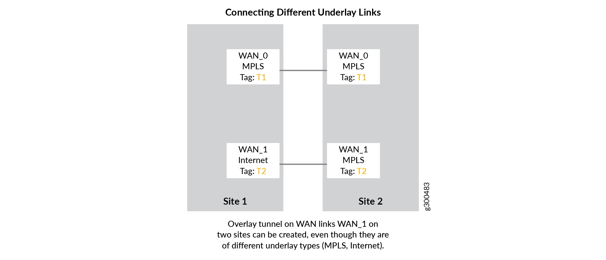
Mesh tags are text-based labels applied to the WAN interfaces of CPE and hub devices during the onboarding process in CSO. CSO is shipped with two default mesh tags: Internet and MPLS. You can create your own mesh tags using the CSO Administration Portal. On-demand, or dynamic, VPNs can only be formed be formed between WAN interfaces that share the same mesh tag.
The following discussion explains how mesh tags work and some of the use cases to which they apply.
As mentioned above, one mesh tag is applied to each WAN interface of the CPE device at each site. On spoke devices such as the NFX150 and NFX250, and most SRX Series Firewalls, only one mesh tag can be applied to each WAN interface. On provider hub and enterprise hub devices such as the SRX4x00 Series devices, multiple mesh tags can be applied to each interface due to the increased VPN capabilities of the devices.
The following list helps to illustrate the various use cases in which mesh tags and dynamic mesh VPNs come into play.
Connecting Different Underlay Links
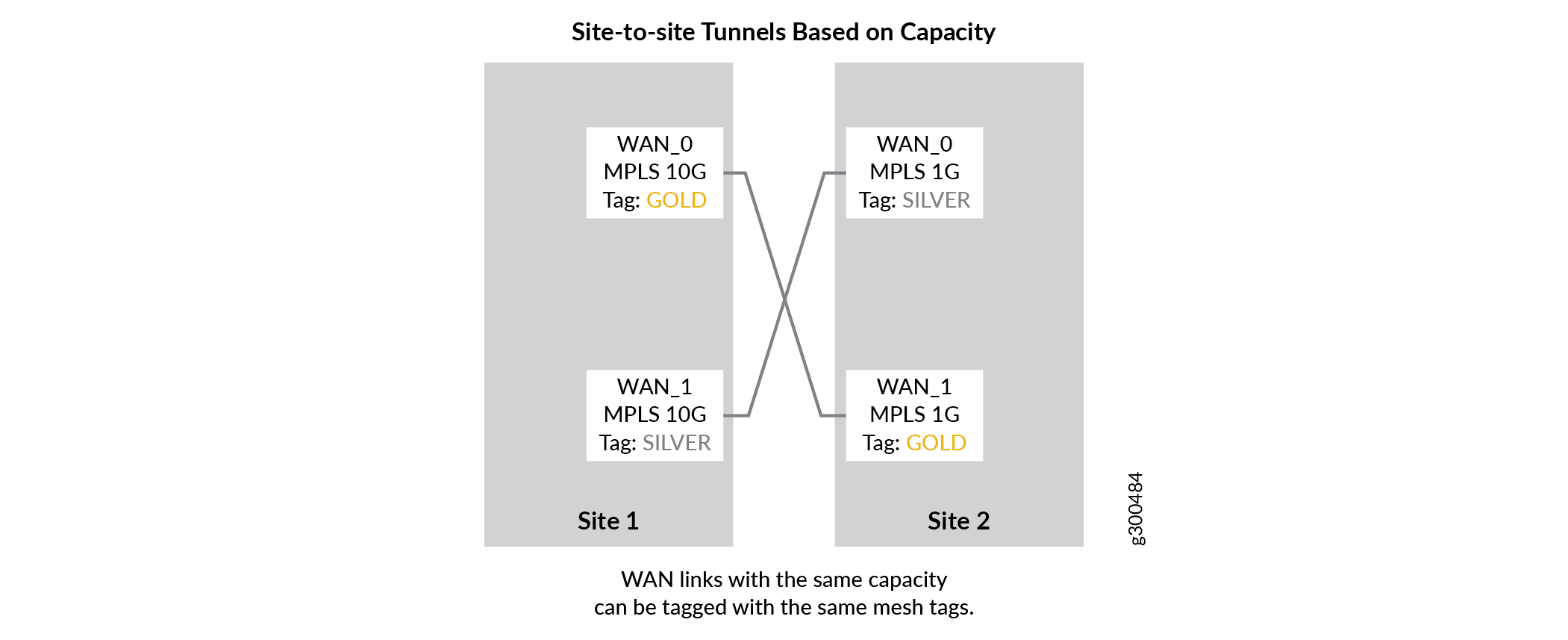
Site-to-Site Tunnels Based on Capacity
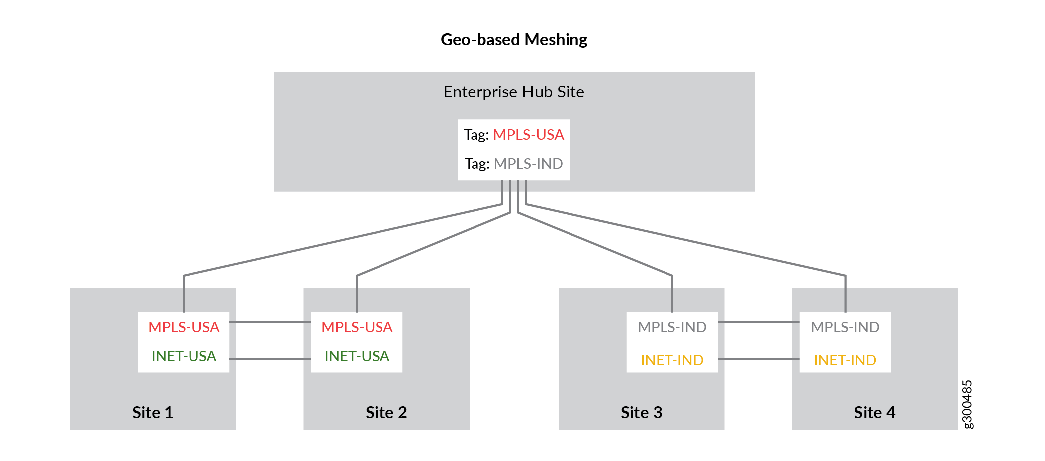
Geo-Based Meshing
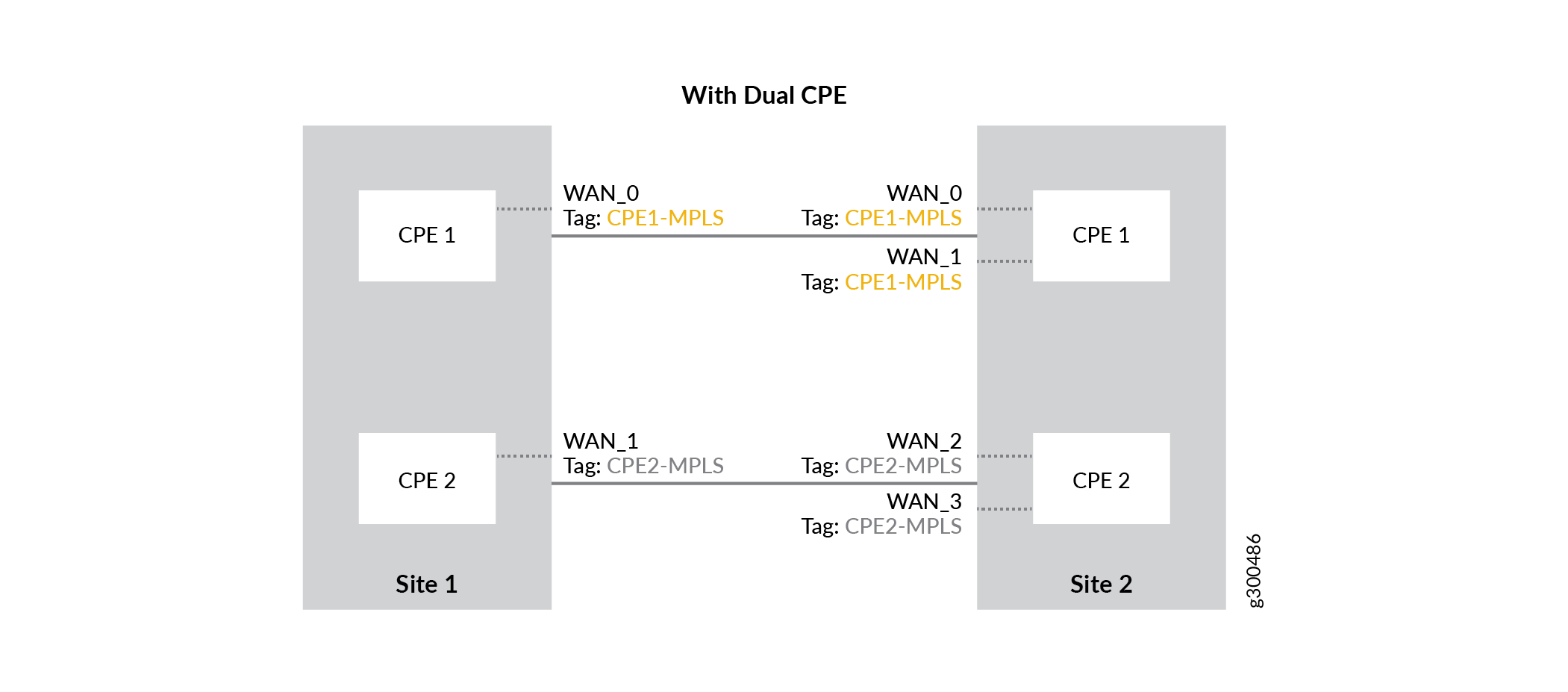
With Dual CPE
Dynamic Mesh Load Balancing
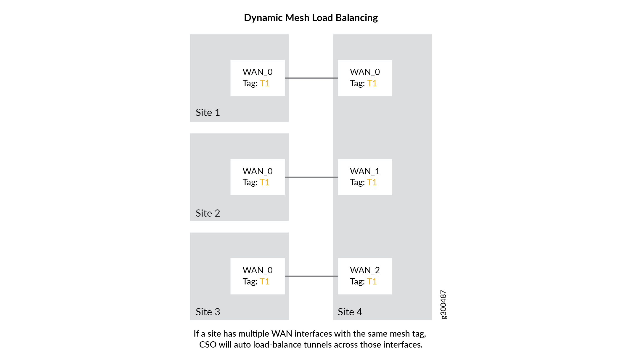
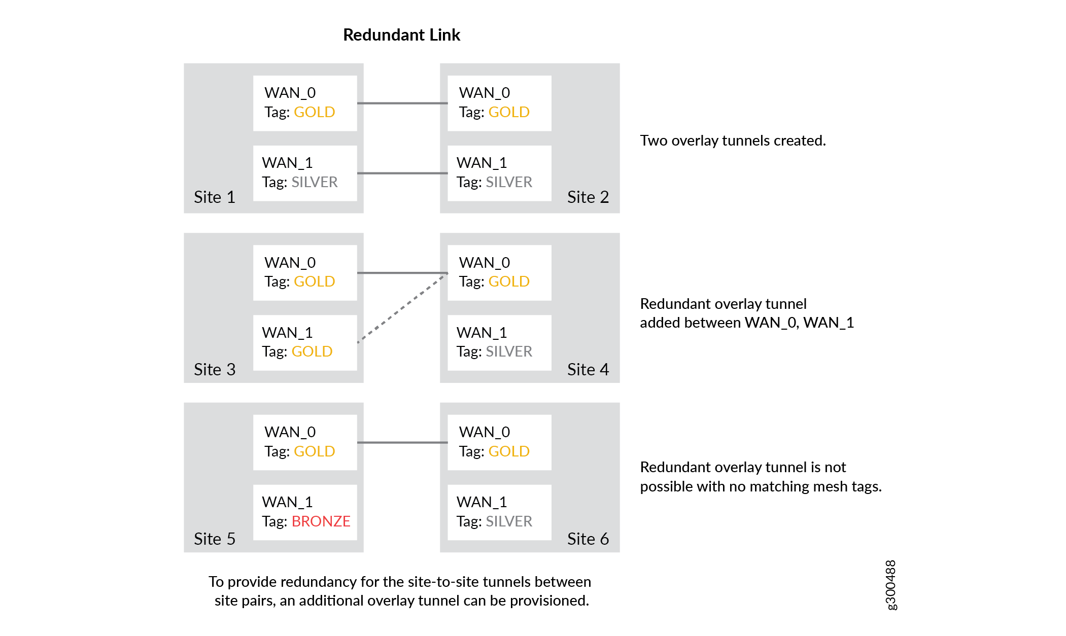
Redundant Link
Dynamic Mesh VPNs
Figure 11 shows a dynamic mesh VPN topology between three spoke sites and describes how the site-to-site VPN is brought up.
1 — Sites and tunnels to Hub sites provisioned using ZTP. Site to site traffic goes through the site to hub data tunnels. | 4 — CSO configures on-demand site-to-site tunnels between the site-pairs. |
2 — CSO receives syslog messages from the devices containing details about traffic rates. | 5 — Site-to-site traffic now switches to the newly formed site-to-site tunnels. |
3 — CSO recognizes that the traffic between Phoenix Site 1 and Houston Site 2 exceeds KPI thresholds. |
Tunnel deletion is also controlled and automated by CSO using traffic thresholds and syslog messaging.
Internet Breakout
While traffic destined for the Internet can be sent across the overlay tunnels and through a central site, the tunnels are more typically intended to support site-to-site traffic. For non-SD-WAN destinations, local breakout provides the option to send the traffic out of the local on-premises device directly to the Internet. Local breakout allows the tenant to use its network bandwidth optimally at each site and to avoid incurring the cost of carrying all traffic to the central site.
Local breakout is an important feature in SD-WAN deployments, as many enterprises nowadays use SaaS services that are hosted outside the corporate network. Since most of these SaaS apps use SSL as the transport and also support single sign-on with the enterprise AAA systems, security concerns are addressed despite sending traffic directly over the Internet.
WAN Interface Options
An on-premises device’s WAN (MPLS and Internet) interfaces can support tunneled and local breakout traffic in any combination:
Tunneled traffic only
Tunneled and local breakout traffic
Local breakout traffic only
Design Options
There are multiple ways to implement local breakout, depending on design requirements.
Breakout at Spoke
Local breakout at spoke sites allows users to access the Internet directly without having to send traffic over the overlay network towards the hub, thus helping to conserve tunnel bandwidth. This option can be implemented on either the Internet or MPLS WAN links. Figure 12 illustrates this concept.
When using local breakout, you can specify either interface-based or pool-based NAT.
Breakout at Provider Hub (Central Breakout)
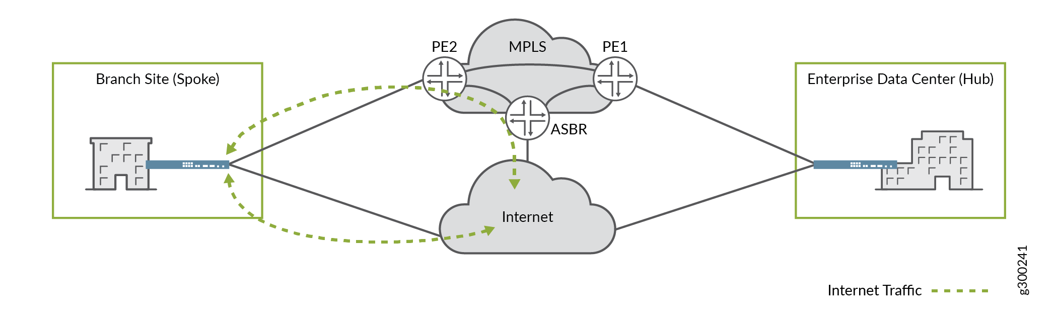
Central breakout at a provider hub site enables hub-and-spoke deployments where spoke sites forward Internet-destined traffic through the overlay network to the provider hub device, which then forwards the traffic out to the Internet as shown in Figure 13.
Central breakout at the hub site is enabled differently than at a spoke site. It can be configured manually in CSO through Stage 2 templates.
Central breakout can also be provided to spoke sites through an Enterprise Hub site. In this scenario, the enterprise hub can eithe rperform local breakout using an underlay network for forwarding or it can receive the default route from the Datacenter department and propagate it to the spokes.
When central breakout is offered at both the provider hub and enterprise hub through the default route method, the default route from the enterprise hub is preferred using BGP local preference.
Cloud Breakout
Another breakout option for Internet-destined traffic, Cloud Breakout, is available to spoke and enterprise hub sites. When cloud breakout is enabled, the spoke site or the enterprise hub site forwards Internet-destined traffic to Zscaler for further security-related processing before it is sent to the Internet. The Zscaler account must be active and accessible prior to sending traffic through the breakout.
Usage Notes for Cloud Breakout
Generic routing encapsulation (GRE) tunnels that use public IP addresses for the WAN links are supported for cloud breakout.
When using GRE tunnels, the CPE devices cannot be behind NAT.
When you configure cloud breakout settings, you can specify IPsec phase 1 parameters, phase 2 parameters, and domain name.
You can specify IP address or hostname validation for cloud breakout nodes.
CSO auto-populates FQDN, preshared keys, and WAN link information and provides the option to change the auto-populated values.
CSO supports high-availability between the WAN links of an SD-WAN spoke site and the cloud breakout node.
WAN link nodes can be configured as active/passive or active/active.
A maximum of two WAN links can be defined between the SD-WAN spoke site and the cloud breakout node.
Order of Preference for Scenarios with Multiple Breakout Options
If multiple breakout options are available to the CPE at the spoke site and there is no breakout policy specified, then the order of preference for breakout is:
Datacenter department/enterprise hub
Local breakout/Cloud breakout
Provider hub (Central)
If multiple breakout options are available to an enterprise hub site, the order of preference for breakout traffic is:
Without SD-WAN policy:
Datacenter department
Hub
With SD-WAN policy:
Local breakout/Cloud breakout
Datacenter department
Provider hub (Central)
Use Cases for Local Breakout
Some use cases for local breakout are described below.
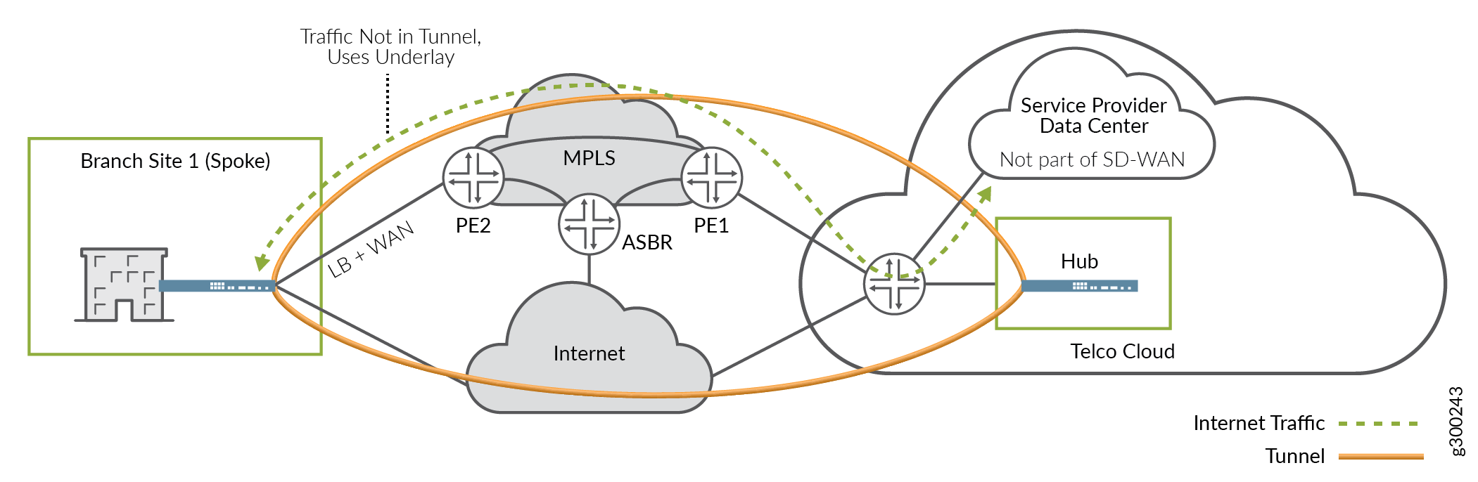
Service Provider Data Center
In this use case, the Enterprise customer uses the service provider’s SD-WAN service for site-to-site inter-connectivity. The customer also uses value-added services hosted out of the service provider’s data center.
At the spoke site, the on-premises device’s MPLS-facing WAN interface is configured to support both tunneled and local breakout traffic. As shown in Figure 14, traffic flows across the network as follows:
Inter-site (SD-WAN) traffic travels across the MPLS network using the overlay tunnel.
DC-destined traffic uses local breakout and travels directly across the underlay MPLS network.
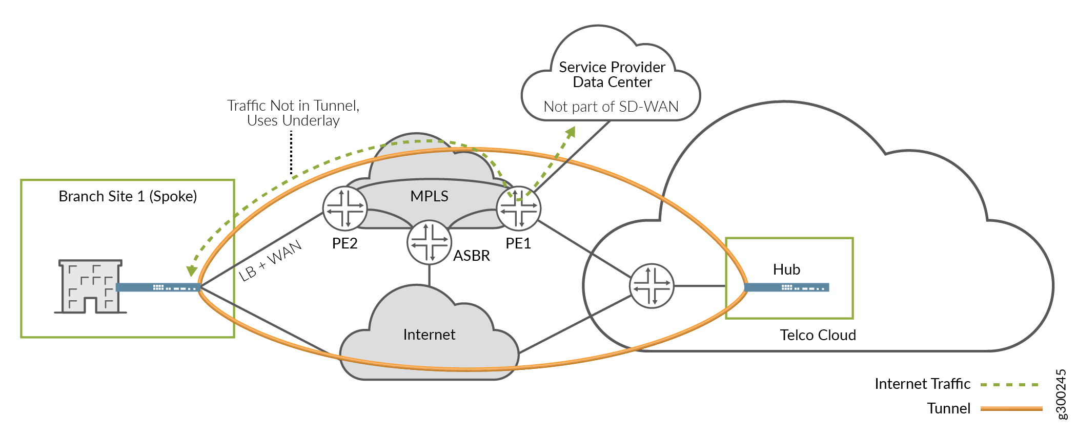
As a variation on this scenario, the data center could be located elsewhere on the MPLS network, perhaps at a POP, as shown in Figure 16. in this case, traffic flows remain generally the same as above.
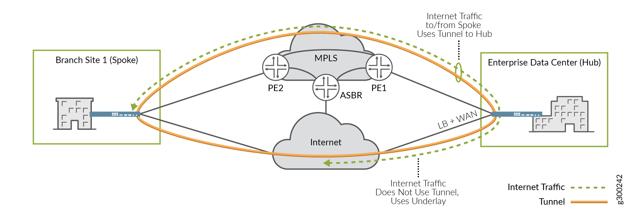
As another variation on this scenario, DC-destined traffic could use the overlay tunnel, breakout at the hub device, and double back to the DC, as shown in Figure 16.
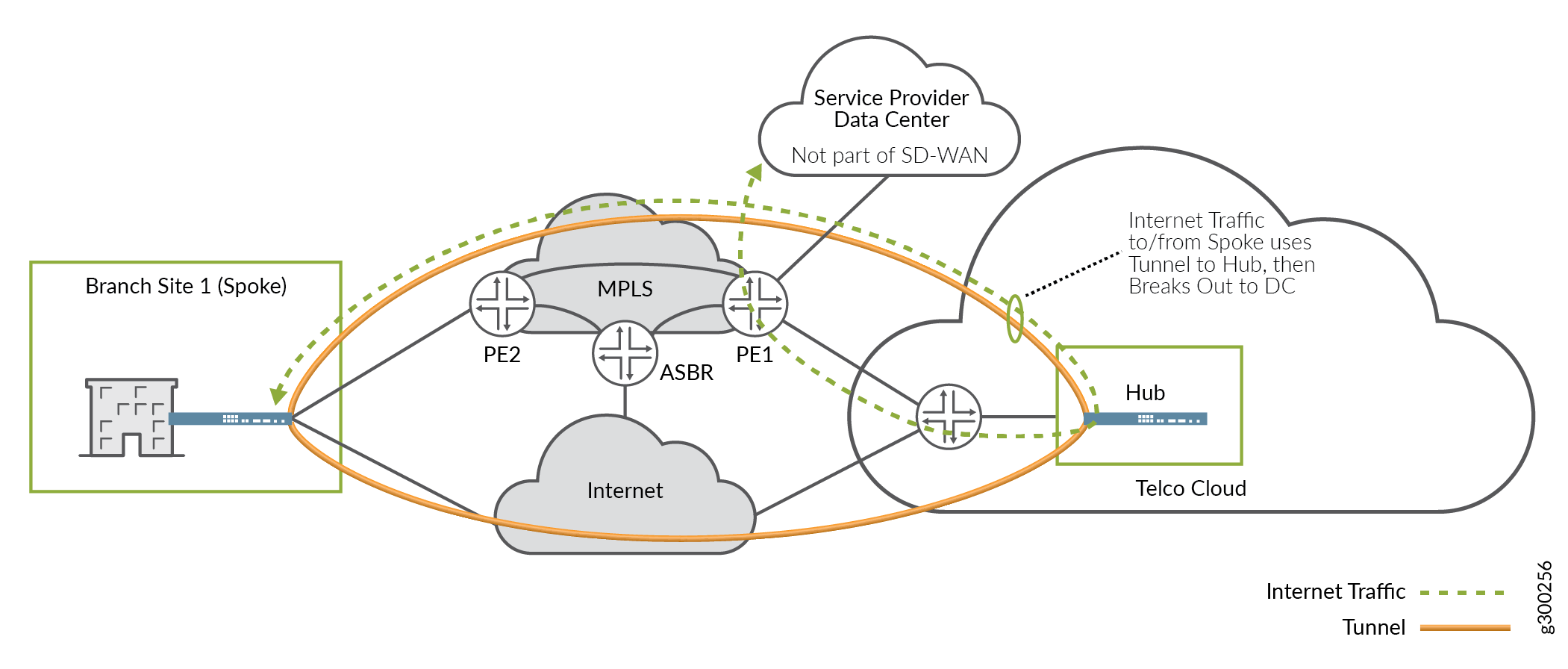
This option has some drawbacks:
It uses more tunnel bandwidth.
It may increase latency as the on-premises device at the spoke site processes and encapsulates more traffic.
It increases the load on the hub device.
It creates a suboptimal path, causing traffic to flow through the tunnels to the hub device, only to have to double back to get to the DC.
However, it also has some advantages:
Using the overlay tunnels, DC-destined traffic can take advantage of SLA services and choose the best path dynamically, thus improving network performance for those applications.
Additional security functions can be offered centrally.
Migration to SD-WAN
In this use case, the enterprise customer has multiple large locations and uses the service provider’s existing MPLS service to provide a full mesh between sites. The customer wants to migrate to SD-WAN, and the implementation is likely to be incremental. Nevertheless, it is critical to maintain connectivity between sites at all times.
Figure 17 illustrates a scenario where the migration is underway. SD-WAN functionality has been added to Site 3 and Site 4, while the other sites have not yet been migrated. At each SD-WAN-enabled site, the on-premises device’s MPLS-facing WAN interface is configured to support both tunneled and local breakout traffic. Traffic flows across the network as follows:
Traffic between the SD-WAN-enabled sites can use the overlay tunnel.
Traffic between an SD-WAN-enabled site and a legacy site uses local breakout and travels directly across the underlay MPLS network.
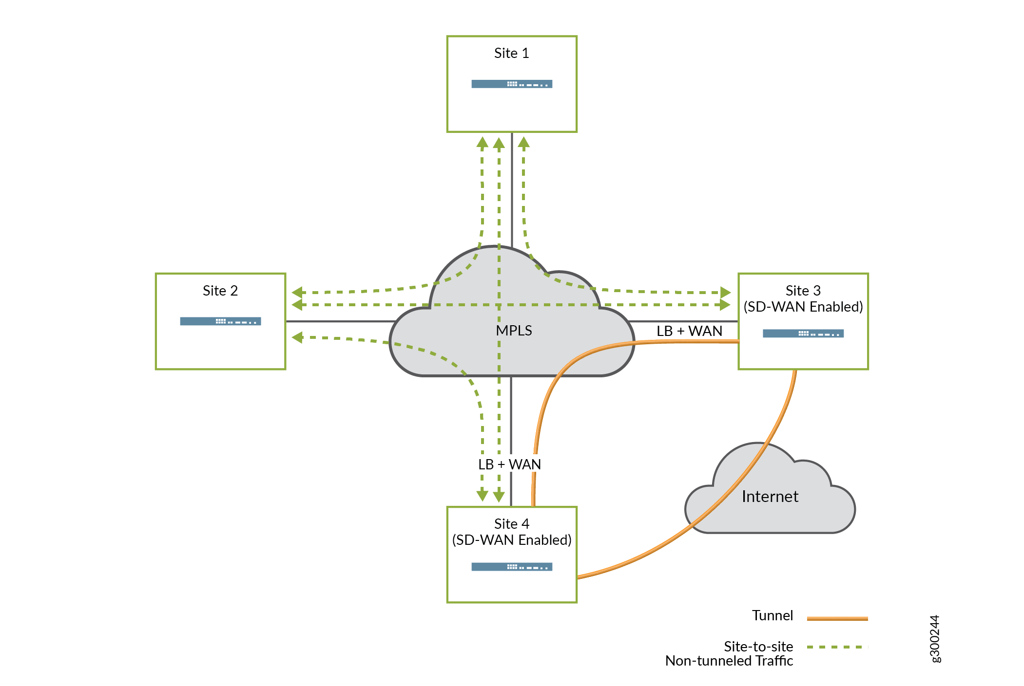
In this case, local breakout is the key to maintaining connectivity between the migrated sites and legacy sites.
Local breakout and NAT
When traffic flows from a tenant VRF to the Internet, NAT must typically be used to translate from the tenant’s private network space to the Internet (public) network space.
At spoke sites, the on-premises devices can use Auto-NAT to automatically perform source NAT on all local breakout traffic. At hub sites, Auto-NAT is not available; however, the CSO UI supports manual creation of NAT rules for these on-premises devices.
Local Breakout and DNS
Configuring an on-premises device as a DHCP server for LAN segments allows you to specify DNS server information for end hosts. For a site with local breakout enabled, it is generally recommended to specify more than than one name server: an internal server for corporate domain name resolution, and a public or ISP server for Internet-destined local breakout traffic.
Network Security
One of the important security considerations for SD-WAN architectures is providing security for data not only at rest, but also in motion. Data security has been enhanced to allow for the use of multi-level PKI for the data and OAM tunnels. This allows CSO to receive multi-level CA certificates from a CA server, push multiple CA certificates to CPE devices, renew and revoke mulitple CA certificates on CPE devices.
CSO supports simple certificate enrollment protocol (SCEP), starting with CSO release 4.1. This allows CSO to:
Act as SCEP server
Act as SCEP cllient
Certificate revocation
Certificate auto-renew
Deploy certificates to a CPE/site
Manage certificates on CPE (site)
Provide GUI support for CA Server information
Site/CPE certificate renewals
Microsoft CA/NDES support
Broker certificates for each site/CPE
A back-end API is provided for programmatic access to PKI features.
Data Plane
Data plane connections can be configured to use IPsec with PKI-based authentication. When used, the local on-premises device encrypts traffic before transmitting it over the network to the remote site and authentication is handled with public-private key pairs.
Management and Control Plane
CSO connects to and configures on-premises devices using SSH for console and NETCONF connections. Starting with CSO Release 4.0, dedicated OAM overlay tunnels help to enhance secure, end-to-end communications between on-premises devices and CSO. IPsec-encrypted and PKI authenticated OAM tunnels, shown in Figure 18, enable on-premises spoke devices to send management, routing, and logging traffic securely over the network to a provider hub. The hub then forwards the traffic to CSO.
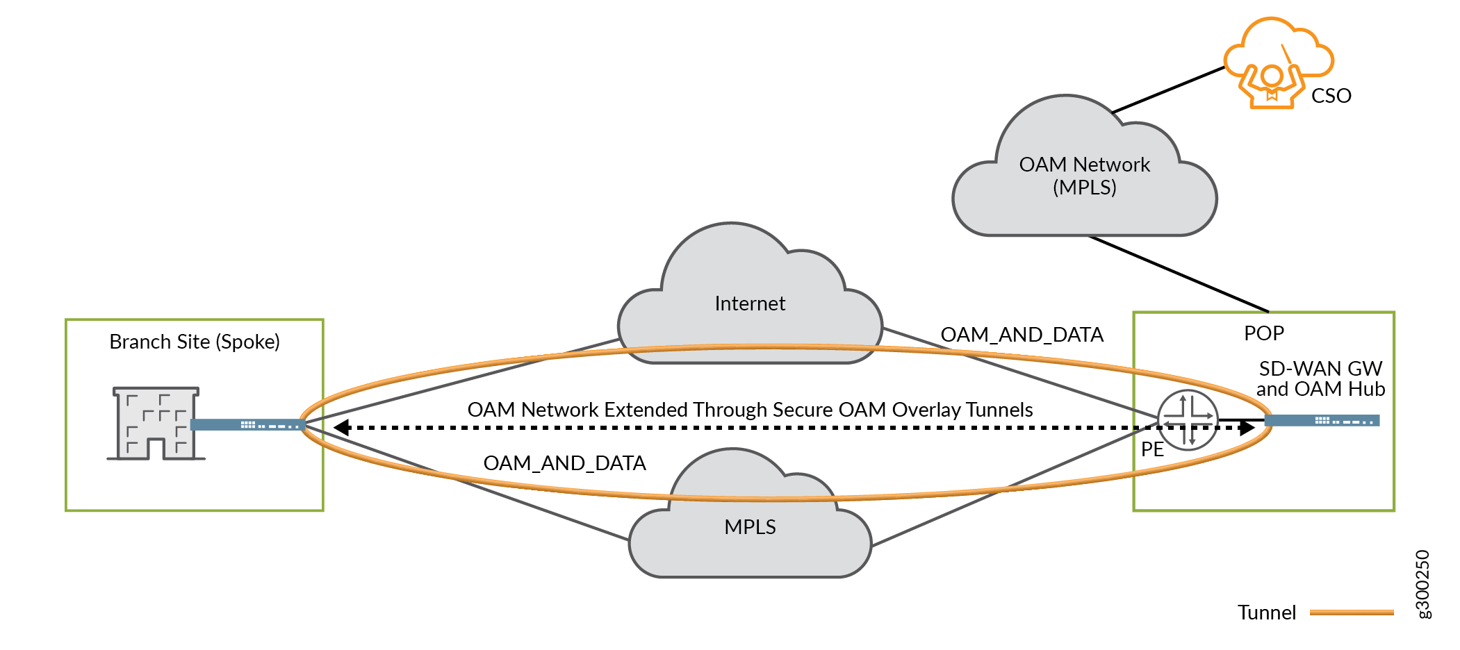
For more detail, see the Secure and Redundant OAM Network section earlier in this guide.