Contrail Service Orchestration Building Blocks
This section introduces you to some of the main elements and concepts you should understand before using CSO. For a more detailed description of these elements and concepts, see the Contrail Service Orchestration Administration Portal User Guide and Contrail Service Orchestration Customer Portal User Guide available at https://www.juniper.net/documentation/product/en_US/contrail-service-orchestration.
Administrators
CSO uses a hierarchical, domain-based administration framework. After CSO installation, the first administrator is named cspadmin by default. This administrator is also known as the global service provider (SP) administrator. This SP administrator has full read and write access to all of the CSO platform from the global domain. In CSOaaS, the cspadmin role is reserved for Juniper Networks. The SP administrator can create, edit, and delete other administrators and operators who are subject to role-based access controls (RBAC) that assign them privileges to the various objects in CSO.
The next level of administrator is the Operating Company or OpCo administrator. In CSOaaS, the OpCo admin is the highest level of administrator available to managed service provider subscribers. The first administrator for any given OpCo is created by the SP administrator. This user has full administrative privileges within an OpCo domain. In a CSO on-premises installation, an OpCo can be thought of as a region-specific service provider within the global service provider. The OpCo administrator can create other administrators and operators within the OpCo domain and its tenants, but cannot affect elements of the global domain or the domain of other OpCos. Successful login by the OpCo administrator places them into the Administration Portal of their OpCo.
The other level of administrator is the Tenant administrator. This administrator has full access to all objects within a single tenant and can create other administrator and operator users within that tenant. The tenant administrator’s login places them into the Customer Portal for that Tenant.
There are also OpCo and tenant operator users. Operator users are created by administrators in their respective domain. By default, operators have read-only access to the elements in their domain.
This is summarized in Table 1:
User |
Portal |
Access |
Domain |
|---|---|---|---|
cspadmin |
Administration |
read/write |
global |
OpCo administrator |
Administration |
read/write |
own OpCo domain |
OpCo operator |
Administration |
read only |
own OpCo domain |
Tenant administrator |
Customer |
read/write |
own Tenant domain |
Tenant operator |
Customer |
read only |
own Tenant domain |
Domains
Each CSO installation supports a single global domain accessible by the SP administrator. For CSOaaS, this domain is inaccessible to subscribers.
Within the global domain, there can exist multiple OpCo domains. In the CSO on-premises installation, these domains correspond to the regional service providers or to whatever scheme you use to split up administrative responsibilities. A simpler administrative setup may choose to have just a single OpCo domain. For CSOaaS, each OpCo domain corresponds to a single managed service provider subscriber.
Within each OpCo domain are the tenant domains. These are the individual enterprises whose WAN connectivity is being managed. For the CSO on-premises installation, these tenants are the customers of either the regional service provider or the global service provider. For CSOaaS, these tenants can be customers of a managed service provider who subscribes to CSOaaS or the tenants can be direct CSOaaS subscribers themselves.
Portals
CSO provides an Administration Portal for the SP and the OpCos to manage their respective domains, and a Customer Portal for tenants to manage their respective domains. Access to any given portal in any given domain is controlled by a user’s login privileges. If your login does not grant access to the Administration Portal, then you cannot see or access any of the elements of this portal.
Administration portals allow tenant creation and creation of other high-level objects that tenants make use of within the customer portals.
Customer portals provide tenant access to a subset of the objects that exist in administration portals. An OpCo administrator can access the Customer Portal for a tenant by clicking the tenant link on the Tenants page in the Administration Portal.
Tenants
CSO uses the tenant element to logically separate one customer from another. An OpCo administrator creates one tenant to represent each customer for which they will provide network services.
Using RBAC and other means such as virtual routing and forwarding (VRF) instances within the network, CSO keeps all tenant and OpCo objects walled within their own space. This ultimately includes the traffic that traverses the customer networks. No individual tenant, its administrators, operators, or customers can see or interact with the objects of another tenant or customer. Tenants can be named in whatever way makes most sense to the SP or OpCo administrator.
Points of Presence (POPs)
A POP is a physical location, usually at the provider network edge, that acts as a demarcation or interchange point between two or more networks. POPs are used in SD-WAN deployments as a way to locate network access and network services closer to the users who need them. Different network services and different connection types can be offered at each POP, depending on need and availability.
In CSO, a POP is typically where tenant traffic breaks out of the tenant overlay network into the provider underlay network or Internet. The SP or OpCo administrator is responsible for creating the POP and adding PE routers and provider hub devices to that POP. Once a provider hub device is added, the device becomes available to be selected for use within a tenant network. POPs can be named in whatever way makes the most sense to the SP or OpCo administrator.
Provider Hub
The SP or OpCo administrator adds the provider hub to the POP. The provider hub can have either or both of the following roles:
OAM - An OAM hub is situated logically between the CPEs and the CSO installation. Its role is to receive OAM traffic from CSO and forward it to the destination CPE devices within secure tunnels. In the other direction, the OAM hub receives OAM traffic from CPE devices within secure tunnels and forwards it to CSO. This role only exists in a CSO on-premises deployment. In CSOaaS, this role is part of the provided service.
DATA - For tenant traffic staying within the tenant network, the data hub acts as a transit hub for site-to-site traffic. For tenant traffic destined for the provider network, the data hub acts as a demarcation point between the overlay tenant network and the underlay provider network. The provider data hub is optional for tenants that have their own enterprise data hubs. If a tenant has an enterprise data hub as well as an assigned provider data hub, the assigned provider data hub acts as a backup.
After the provider hub is added to the POP, the SP or OpCo administrator can then associate the provider hub site with a tenant.
Sites
Before CSO can build the overlay tenant network, CSO needs to know about all the sites in that network. A site can be a provider hub site, an enterprise hub site, an on-premises spoke site, or a cloud spoke site (Table 2).
Available Site Types |
Added By |
Uses |
Service Notes |
|---|---|---|---|
On-Premises Spoke |
The tenant administrator adds the on-premises spoke site. |
NFX Series or SRX Series Firewalls placed at branch sites in either a hub–and–spoke or full mesh topology. |
An on-premises spoke has the following capabilities: SRX Series
NFX Series
Note:
ZTP using an xDSL interface will not work if the link is PPPoE. If the link is bridged and uses DHCP, then ZTP will work on xDSL interfaces. |
Cloud Spoke |
The tenant administrator adds the cloud spoke site. |
vSRX Virtual Firewall placed in a tenant’s Amazon Web Services (AWS) Virtual Private Cloud (VPC) |
A cloud spoke has the following capabilities:
|
Provider Hub |
The SP or OpCo administrator adds provider hub sites for a tenant. Adding a provider hub site means associating an existing provider hub device with the tenant. To do this, the SP or OpCo administrator switches to the Customer Portal for the tenant and adds the provider hub site by selecting the POP and the provider hub device from the list of available POPs and provider hub devices. The name of the provider hub site is automatically set to the name of the selected provider hub device. |
SRX Series Firewalls placed in a central role in a service provider cloud. The hub devices establish IPSec tunnels with the spoke sites. Provider hub devices are multi-tenant (shared amongst multiple sites) through the use of VRF instances configured on them. |
A provider hub has the following capabilities:
|
Enterprise Hub |
The tenant administrator adds the enterprise hub site. |
Provides additional hub-like capabilities to a normal spoke site. |
An enterprise hub has the following capabilities:
|
Topologies
CSO supports the following network topologies:
Standalone Topology — This topology is one in which the customers or users of network services remain separate from each other with no means of communication amongst themselves, such as in the NGFW solution. The NGFW solution provides for remote site security with SRX Series next-generation firewall devices (Figure 1).
Figure 1: Standalone NGFW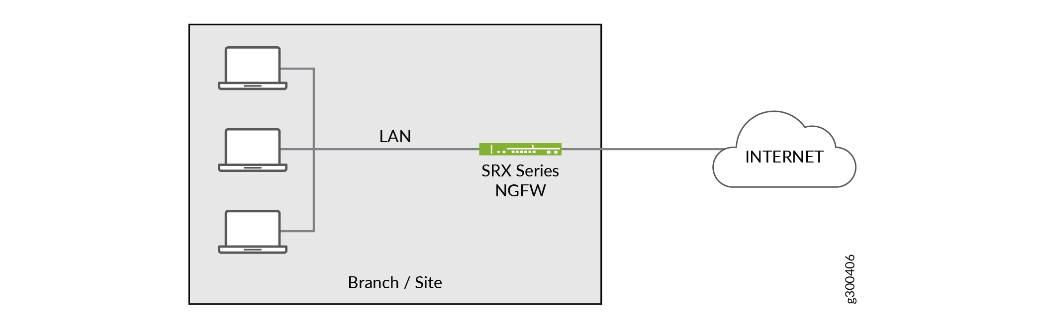
Hub–and–Spoke Topology — This topology is supported for SD–WAN deployments. All traffic, including spoke-to-spoke traffic, passes through the hub site.
Figure 2 shows the hub–and-spoke concept.
Figure 2: Hub-and-Spoke Topology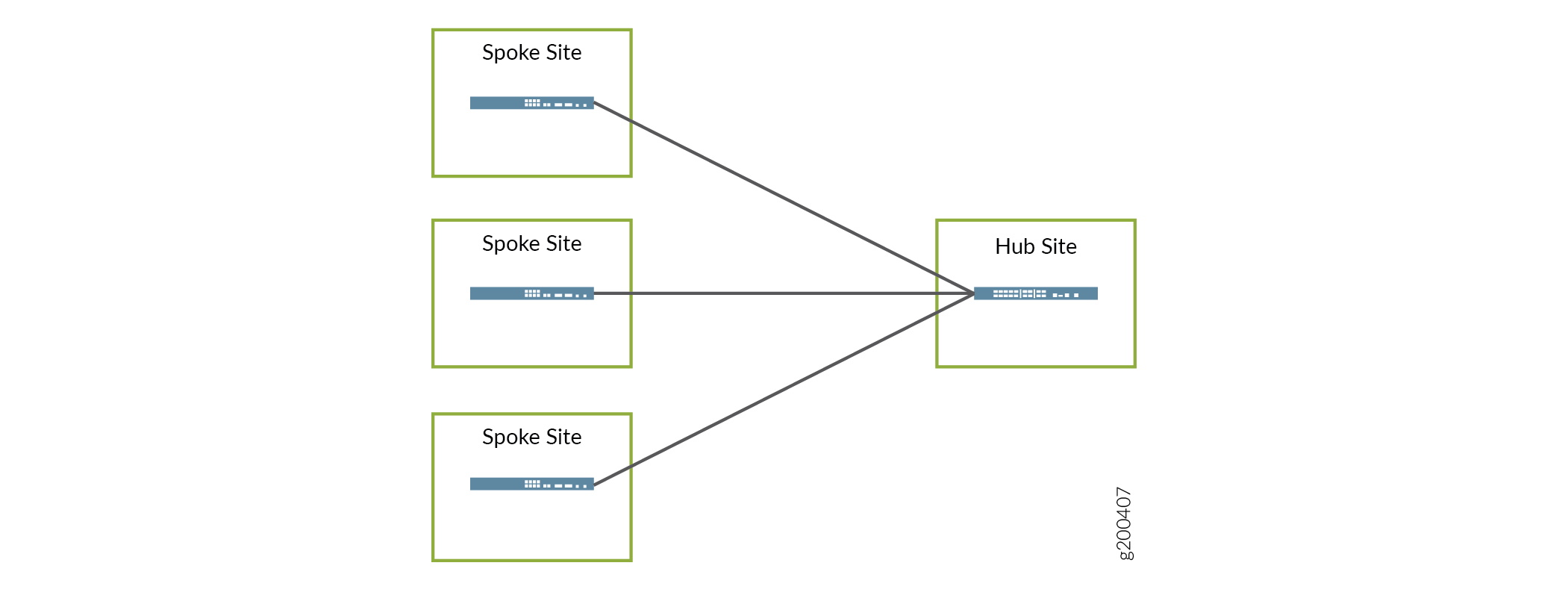
Dynamic Mesh Topology — This topology is supported for SD-WAN deployments. Figure 3 shows an example of a dynamic mesh topology where traffic can flow directly from any site to any site. Site-to-site tunnels are created dynamically based on traffic thresholds, thereby conserving resources and improving overall performance. Mesh tags are used to determine which sites can connect together.
Figure 3: Dynamic Mesh Topology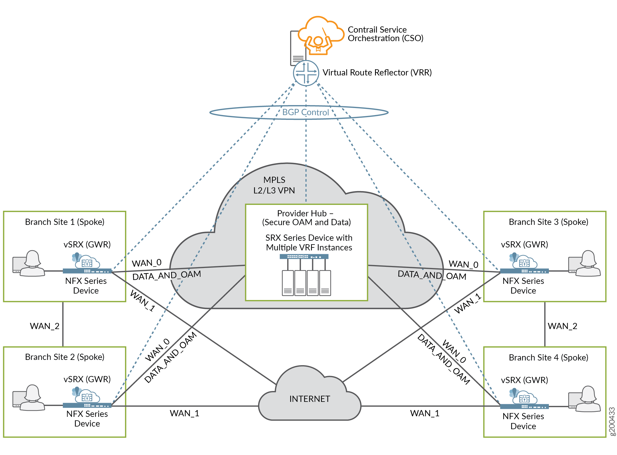
Virtual Route Reflector (VRR)
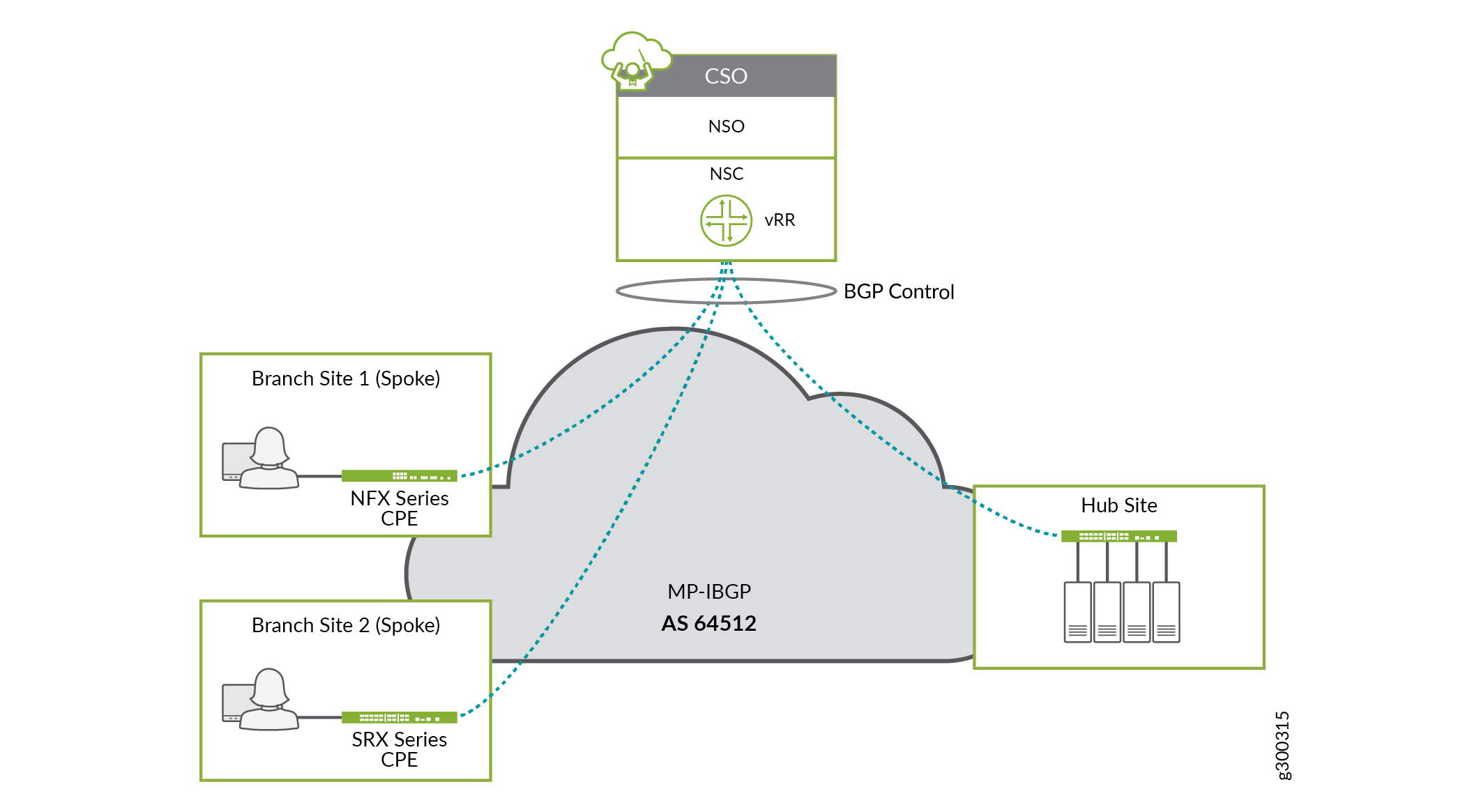
The VRR is part of CSO's SD–WAN controller. It is one of the virtual machines that gets provisioned and installed during the installation process. To facilitate the routing needed in the SD–WAN deployment, the VRR forms overlay BGP sessions with CPE spokes and hub devices over the underlay interface designated for OAM capability. You make this selection with the Configure Site workflow for site onboarding. Figure 4 illustrates the concept of the VRR
SLA-Based Steering Profiles and Policies
CSO allows for the creation of SLA–Based steering profiles that can be mapped to SD–WAN policy intents for traffic management in an SD–WAN deployment. The profiles are designed to steer traffic to a specific WAN link based on SLA parameters such as packet loss, round trip time (rtt), and jitter thresholds. SLA steering profiles are created for global application traffic types for all tenants. An SLA profile consists of a set of configurable constraints that can be defined in the Administration Portal.
You can set:
Path preference for each of the connection paths from site–to–site
Path preference for each of the connection paths from site–to–hub
Threshold parameters for throughput
Threshold parameters for packet loss
Threshold parameters for latency
Threshold parameters for jitter
Class of service for various types of traffic
Rate limiters to control upstream and downstream traffic rates and burst sizes
Once the steering profile exists, an intent-based SD–WAN policy can be created that applies that profile to specific sites or departments and against specific types of application traffic such as SSH and HTTP.
When creating an SLA profile, you must set either path preference or one of the SLA parameters. Both fields cannot be left blank at the same time.
See SLA Profiles and SD-WAN Policies Overview for more details.
Path Based Steering Profiles
Path based steering profiles are a simplified way to steer global application traffic types onto a specific WAN path. With these profiles, you do not need to configure any SLA parameters. All you need to do is specify which available path you want a specific traffic type to take. Just as with SLA steering profiles, you can set rate limiting parameters for these profiles. You must also assign these profiles to an SLA policy before they take effect.
Intent-based Firewall Policies
Accessed through the Customer Portal, CSO presents firewall policies as intent-based policies. Firewall policies provide security functionality by enforcing intents on traffic that passes through a device. Traffic is permitted or denied based on the action defined as the firewall policy intent. If your intention is to block HTTP-based traffic from social media sites, but allow HTTP-based traffic from Microsoft Outlook, you can create an intent policy to do that.
See Firewall Policy Overview for more information.
Software Image Management
The CSO Administration Portal allows SP administrators (cspadmin) to upload device software images and VNF images on the Resources > Images page. The cspadmin user in an on-premises CSO deployment can upload device images for supported SRX Series Firewalls (including vSRX Virtual Firewall), NFX Series devices, and EX Series devices.
For CSOaaS, an OpCo administrator can see the images that have been uploaded to CSO by Juniper Networks. He or she can also stage and deploy uploaded device images to CPE devices and EX Series access switches.