MPLS Support in cRPD
How MPLS Is Supported on cRPD
MPLS configuration is supported on cRPD for forwarding packets to the destination in MPLS network.
With MPLS, only the first device does a routing lookup. Instead of finding the next hop, the device finds the ultimate destination along with a path to that destination. The path of an MPLS packet is called a label-switched path (LSP). LSPs are unidirectional routes through a network or an autonomous system (AS). MPLS routers within an AS determine paths through a network through the exchange of MPLS traffic engineering information. Using these paths, the routers direct traffic through the network along an established route. Rather than selecting the next hop along the path as in IP routing, each router is responsible for forwarding the packet to a predetermined next hop address.
Routers that are part of the LSP are label-switching routers (LSRs). An MPLS LSP is established using static LSPs. A static LSP requires each router along the path to be configured explicitly. You must manually configure the path and its associated label values.
cRPD supports only a limited number of Junos OS MPLS features.
You can configure MPLS interface, ipv6-tunneling, label-history, label-range, and static-label-switched-path in cRPD CLI under the edit protocols mpls hierarchy.
Supported Features
BGP configuration
MPLS using PRPD API
BGP labeled unicast configuration
See Also
Example: Configure Static Label Switched Paths for MPLS in cRPD
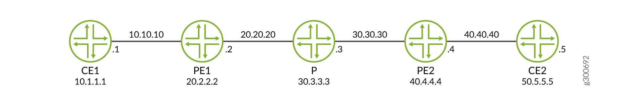
This example shows how the VPN traffic flows through a v4 MPLS tunnel among PEs by configuring BGP and MPLS static label switched paths.
Requirements
This example uses the following hardware and software components:
-
Ubuntu software version 18.04
-
Linux kernel version 4.5 or later
-
cRPD software Release version 19.4R1 or later
Before you configure a static LSP for MPLS forwarding, you must install the basic components:
-
MPLS modules on host OS on which cRPD instance is created. For details, see Configure Settings on Host OS.
-
Provider edge router (PE1), provider router (P), and provider edge router (PE2). For installation, see Install cRPD on Docker.
Overview
In this example, PE1 acts as a Label Edge Router or ingress node to the MPLS network, which encapsulates the packets by attaching labels. P acts as Label Switching Router that transfers MPLS packets using labels in the MPLS network.
To configure MPLS, you must first create one or more named paths on the ingress and transit routers. For each path, you can specify some or all transit routers in the path.
Configuring static label-switched paths (LSPs) for MPLS is similar to configuring static routes on individual routers.
Configuration
To configure static LSP for MPLS on cRPD:
Configuring PE1 Router
Step-by-Step Procedure
To configure the static LSP:
-
Create the tables inet.0 and mpls.0.
[edit routing-options] user@crpd1# set rib inet.0 user@crpd1# set rib mpls.0 user@crpd1# set router-id 20.2.2.2 -
Configure BGP session.
[edit protocols bgp group VPN] user@crpd1# set type internal local-address 20.2.2.2 family inet-vpn unicast user@crpd1# set local-as 5 user@crpd1# set neighbor 40.4.4.4 family inet-vpn unicast -
Configure the static label range and ingress static LSP parameters.
[edit protocols mpls] user@crpd1# set interface all user@crpd1# set label-range static-label-range 1000000 1048575 user@crpd1# set static-label-switched-path pe2 ingress install 40.4.4.4/32 active user@crpd1# set static-label-switched-path pe2 ingress to 40.4.4.4 next-hop 20.20.20.2 push 1000001 -
Configure a static route from the ingress PE2.
[edit routing-options static] user@crpd1# set route 20.2.2.2/32 next-hop 20.20.20.2 user@crpd1# set route 40.4.4.4/32 static-lsp-next-hop pe2 -
Configure a VRF routing instance on PE1 and other routing instance parameters.
[edit routing-instances vrfblue]
user@crpd1# set routing-options static route 10.1.1.1/32 next-hop 10.10.10.1
user@crpd1# set route-distinguisher 100:100
user@crpd1# set vrf-target target:100:100
user@crpd1# set interface all
Results
From configuration mode, confirm your configuration
by entering the show protocols bgp and run show configuration
protocols mpls commands on PE1. If the output does not display
the intended configuration, repeat the configuration instructions
in this example to correct it.
user@crpd1# show protocols bgp
group VPN {
    type internal;
    local-address 20.2.2.2;
    family inet-vpn {
        unicast;
    }
    local-as 5;
    neighbor 40.4.4.4 {
        family inet-vpn {
            unicast;
        }
    }
}
user@crpd1# run show configuration protocols mpls
interface all;
static-label-switched-path pe2 {
    ingress {
        next-hop 20.20.20.3;
        to 40.4.4.4;
        push 1000001;
    }
}
If you are done configuring the device, enter commit from configuration mode.
Configuring Provider P Router.
Step-by-Step Procedure
To configure the static LSP:
-
Configure router ID for router P.
[edit routing-options] user@crpd2# set rib mpls.0 user@crpd2# set router-id 30.3.3.3 -
Configure a transit static LSP for swap and pop labels.
[edit protocols mpls]
user@crpd2# set label-range static-label-range 1000000 1048575
user@crpd2# set static-label-switched-path pe2 transit 1000001 next-hop 30.30.30.4 swap 1000002
user@crpd2# set static-label-switched-path pe1 transit 1000003 next-hop 20.20.20.2 swap 1000004
user@crpd2# set static-label-switched-path pe2 transit 1000001 pop next-hop 30.30.30.4
user@crpd2# set static-label-switched-path pe1 transit 1000003 pop next-hop 20.20.20.2
Results
From configuration mode, confirm your configuration
by entering the show protocols bgp, run show configuration
protocols mpls, and run show mpls interface commands
on P. If the output does not display the intended configuration, repeat
the configuration instructions in this example to correct it.
user@crpd2# run show configuration protocols mpls
interface all;
static-label-switched-path pe1 {
    transit 1000003 {
        next-hop 20.20.20.2;
        swap 1000004;
    }
}
static-label-switched-path pe2 {
    transit 1000001 {
        next-hop 30.30.30.4;
        swap 1000002;
    }
}
If you are done configuring the device, enter commit from configuration mode.
Configuring PE2 Router
Step-by-Step Procedure
To configure the static LSP for MPLS on PE2:
-
Configure BGP session.
[edit protocols bgp group VPN ] user@crpd3# set type internal local-address 40.4.4.4 family inet-vpn unicast user@crpd3# set local-as 5 user@crpd3# set neighbor 20.2.2.2 family inet-vpn unicast -
Configure the ingress static LSP parameters.
[edit protocols mpls ] user@crpd3# set interface all user@crpd3# set label-range static-label-range 1000000 1048575 user@crpd3# set static-label-switched-path pe1 ingress install 20.2.2.2/32 active user@crpd3# set static-label-switched-path pe1 ingress to 20.2.2.2 next-hop 30.30.30.4 push 1000003 -
Configure router ID and a static route from the ingress PE1.
[edit routing-options] user@crpd3# set rib inet.0 user@crpd3# set router-id 40.4.4.4 user@crpd3# set static route 40.4.4.4/32 next-hop 30.30.30.4 user@crpd3# set static route 20.2.2.2/32 static-lsp-next-hop pe1 -
Configure a VRF routing instance on PE2 and other routing instance parameters.
[edit routing-instances vrfblue]
user@crpd3# set routing-options static route 50.5.5.5/32 next-hop 40.40.40.5
user@crpd3# set route-distinguisher 100:100
user@crpd3# set vrf-target target:100:100
user@crpd3# set interface all
Results
From configuration mode, confirm your configuration
by entering the run show configuration protocols mpls and run show mpls interface commands on PE2. If the output does
not display the intended configuration, repeat the configuration instructions
in this example to correct it.
user@crpd3# show protocols bgp
group VPN {
    type internal;
    local-address 40.4.4.4;
    family inet-vpn {
        unicast;
    }
    local-as 5;
    neighbor 20.2.2.2 {
        family inet-vpn {
            unicast;
        }
    }
}
user@crpd3# run show configuration protocols mpls
interface all;
static-label-switched-path pe2 {
    ingress {
        next-hop 20.20.20.3;
        to 40.4.4.4;
        push 1000001;
    }
}
If you are done configuring the device, enter commit from configuration mode.
Verification
Verify MPLS forwarding on PE1
Purpose
To verify the configuration for MPLS on PE1.
Action
From operational mode, enter the show route table vrfblue.inet.0 50.5.5.5
command:
user@crpd1> show route table vrfblue.inet.0 50.5.5.5
vrfblue.inet.0: 5 destinations, 5 routes (5 active, 0 holddown, 0 hidden)
+ = Active Route, - = Last Active, * = Both

50.5.5.5/32         *[BGP/170] 00:01:03, localpref 100, from 40.4.4.4
                      AS path: I, validation-state: unverified
                    >  to 20.20.20.3 via pe1-p, Push 299776, Push 1000001(top)
From operational mode, enter the show mpls label
usage command:
user@crpd1> show mpls label usage
Label space Total   Available        Applications
LSI         999984  999983 (100.00%) BGP/LDP VPLS with no-tunnel-services, BGP L3VPN with vrf-table-label
Block       999984  999983 (100.00%) BGP/LDP VPLS with tunnel-services, BGP L2VPN
Dynamic     999984  999983 (100.00%) RSVP, LDP, PW, L3VPN, RSVP-P2MP, LDP-P2MP, MVPN, EVPN, BGP
Static      48576   48576  (100.00%) Static LSP, Static PW
Effective Ranges
Range name  Shared with Start   End
Dynamic     16      999999
Static      1000000 1048575
Configured Ranges
Range name  Shared with Start   End
Dynamic     16      999999
Static      1000000 1048575
From operational mode, enter the show mpls static-lsp command:
user@crpd1> show mpls static-lsp
Ingress LSPs:
LSPname                             To              State
pe2                                 40.4.4.4         Up
Total 1, displayed 1, Up 1, Down 0

Transit LSPs:
Total 0, displayed 0, Up 0, Down 0

Bypass LSPs:
Total 0, displayed 0, Up 0, Down 0

Segment LSPs:
Total 0, displayed 0, Up 0, Down 0
From operational mode, enter the show route table
inet.3 command:
user@crpd1> show route table inet.3
inet.3: 1 destinations, 1 routes (1 active, 0 holddown, 0 hidden)
+ = Active Route, - = Last Active, * = Both

40.4.4.4/32         *[MPLS/6/1] 00:04:44, metric 0
                    >  to 20.20.20.3 via pe1-p, Push 1000001
From operational mode, enter the show route table
mpls.0 command:
user@crpd1> show route table mpls.0
mpls.0: 6 destinations, 6 routes (6 active, 0 holddown, 0 hidden)
+ = Active Route, - = Last Active, * = Both

0                  *[MPLS/0] 00:15:45, metric 1
                       Receive
1                  *[MPLS/0] 00:15:45, metric 1
                       Receive
2                  *[MPLS/0] 00:15:45, metric 1
                       Receive
13                 *[MPLS/0] 00:15:45, metric 1
                       Receive
299776             *[VPN/170] 00:06:32
                    >  to 10.10.10.1 via pe1-ce1, Pop
299776(S=0)        *[VPN/170] 00:06:32
                    >  to 10.10.10.1 via pe1-ce1, Pop
From operational mode, enter the ip route list table 5 50.5.5.5 command:
user@crpd1> ip route list table 5 50.5.5.5
50.5.5.5 encap mpls 1000001/299776 via 20.20.20.3 dev pe1-p proto 22
From operational mode, enter the ip -f mpls route command:
user@crpd1> ip -f mpls route
299776 via inet 10.10.10.1 dev pe1-ce1 proto 22
Verify MPLS forwarding on P
Purpose
To verify the configuration for MPLS on P.
Action
From shell mode, enter the show route table mpls.0 command:
user@crpd2> show route table mpls.0
mpls.0: 10 destinations, 10 routes (10 active, 0 holddown, 0 hidden)
+ = Active Route, - = Last Active, * = Both

0                  *[MPLS/0] 00:00:11, metric 1
                       Receive
1                  *[MPLS/0] 00:00:11, metric 1
                       Receive
2                  *[MPLS/0] 00:00:11, metric 1
                       Receive
13                 *[MPLS/0] 00:00:11, metric 1
                       Receive
299776             *[VPN/170] 00:00:05
                    >  to 20.20.20.2 via p-pe1, Pop
299776(S=0)        *[VPN/170] 00:00:05
                    >  to 20.20.20.2 via p-pe1, Pop
299792             *[VPN/170] 00:00:05
                    >  to 30.30.30.4 via p-pe2, Pop
299792(S=0)        *[VPN/170] 00:00:05
                    >  to 30.30.30.4 via p-pe2, Pop
1000001            *[MPLS/6] 00:00:11, metric 1
                    >  to 30.30.30.4 via p-pe2, Swap 1000002
1000003            *[MPLS/6] 00:00:11, metric 1
> to 20.20.20.2 via p-pe1, Swap 1000004user@crpd2> show mpls static-lsp
Ingress LSPs:
Total 0, displayed 0, Up 0, Down 0

Transit LSPs:
LSPname                             Incoming-label  State
pe1                                 1000003         Up
pe2                                 1000001         Up
Total 2, displayed 2, Up 2, Down 0

Bypass LSPs:
Total 0, displayed 0, Up 0, Down 0

Segment LSPs:
Total 0, displayed 0, Up 0, Down 0
From bash shell mode, enter the ip -f mpls route command:
user@crpd2:/# ip -f mpls route
299776 via inet 20.20.20.2 dev p-pe1 proto 22
299792 via inet 30.30.30.4 dev p-pe2 proto 22
1000001 as to 1000002 via inet 30.30.30.4 dev p-pe2 proto 22
1000003 as to 1000004 via inet 20.20.20.2 dev p-pe1 proto 22
Verify MPLS forwarding on PE2
Purpose
To verify the configuration for MPLS on P.
Action
From shell mode, enter the show route table vrfblue.inet.0 10.1.1.1
command:
user@crpd3> show route table vrfblue.inet.0 10.1.1.1
vrfblue.inet.0: 5 destinations, 5 routes (5 active, 0 holddown, 0 hidden)
+ = Active Route, - = Last Active, * = Both

10.1.1.1/32         *[BGP/170] 00:03:00, localpref 100, from 2.2.2.2
                      AS path: I, validation-state: unverified
> to 30.30.30.3 via pe2-p, Push 299776, Push 1000003(top)user@crpd3> show mpls static-lsp
Ingress LSPs:
LSPname                             To              State
pe1                                 20.2.2.2         Up
Total 1, displayed 1, Up 1, Down 0

Transit LSPs:
LSPname                             Incoming-label  State
pe2                                 1000002         Dn
Total 1, displayed 1, Up 0, Down 1

Bypass LSPs:
Total 0, displayed 0, Up 0, Down 0

Segment LSPs:
Total 0, displayed 0, Up 0, Down 0
user@crpd3> show route table mpls.0
mpls.0: 6 destinations, 6 routes (6 active, 0 holddown, 0 hidden)
+ = Active Route, - = Last Active, * = Both

0                  *[MPLS/0] 00:17:31, metric 1
                       Receive
1                  *[MPLS/0] 00:17:31, metric 1
                       Receive
2                  *[MPLS/0] 00:17:31, metric 1
                       Receive
13                 *[MPLS/0] 00:17:31, metric 1
                       Receive
299776             *[VPN/170] 00:03:07
                    >  to 40.40.40.5 via pe2-ce2, Pop
299776(S=0)        *[VPN/170] 00:03:07
                    >  to 40.40.40.5 via pe2-ce2, Pop
From bash shell mode, enter the ip -f mpls route command:
user@crpd3:/# ip -f mpls route
299776 via inet 40.40.40.5 dev pe2-ce2 proto 22
From bash shell mode, enter the ip route list table 5 10.1.1.1 command:
user@crpd3:/# ip route list table 5 10.1.1.1
10.1.1.1 encap mpls 1000003/299776 via 30.30.30.3 dev pe2-p proto 22
Meaning
You can verify the static LSP between PEs are up on
all the devices and the routes are populated in the corresponding
route tables inet.o and inet.3 and in the Linux
FIB.