Layer 3 Overlay Support in cRPD
Overview
Virtual routing and forwarding (VRF) instances are supported in cRPD along with the support of MPLS and Multiprotocol BGP to provide overlay functionality.
A routing instance is a collection of routing tables, interfaces,
and routing protocol parameters. To implement Layer 3 VPNs, you configure
one routing instance for each VPN. A VRF is a network device in the
Linux kernel and the device is associated with table-id. You configure the routing instances on PE routers only. You can
create VRFs in the Linux network. VRF device implementation impacts
only Layer 3 and above. Each VPN routing instance consists of the
following components:
VRF table—On each PE router, you configure one VRF table for each VPN.
Policy rules—These control the import of routes into and the export of routes from the VRF table.
One or more routing protocols that install routes from CE routers into the VRF table—You can use the BGP, OSPF, and RIP routing protocols, and you can use static routes.
When a VRF device is created, it is associated with a routing table. Packets that come in through enslaved devices to the VRF are looked up in the routing table associated with the VRF device. Similarly, egress routing rules are used to send packets to the VRF driver before sending it out on the actual interface.
VRF is used to manage routes and to forward traffic based on independent forwarding tables in
VRF. RPD creates multiple routing tables for every routing
instance of type vrf. The tables are one for
each family address. You need to configure a routing instance
for each VPN on each of the PE routers participating in the VPN.
You can configure routing instances using the [edit
routing-instances] hierarchy. The routing
instance of type vrf is only supported on cRPD.
You can create multiple instances of BFD, BGP, IS-IS, OSPF version
2 (referred as OSPF), OSPF version 3 (OSPFv3), and ICMP router discovery
under a VRF using the [edit routing-instances routing-instance-name
protocols] hierarchy. You can configure protocol independent
routing using the edit routing-instances instance-name routing-options hierarchy.
Layer-3 Overlay supports the following tunneling protocols in cRPD:
Static routes in inet.3
BGP labeled unicast
GRE tunneling
MPLS static LSPs
Routes programmed using programmable-rpd APIs
direct-ebgp-peering on MPLS enabled interface
Configure Interfaces under a VRF
The enslavement of devices is done by RPD that is interfaces configured under the routing instance are migrated (enslaved) to the vrf-device by RPD using a netlink message sent to the kernel.
When an interface is configured under the routing instance of
type vrf, if such a link has been learnt from the kernel
and the link is not associated to the correct table, RPD sends a netlink
notification to enslave the link. If the link does not exist or RPD
has not learnt about the link, whenever the link is created or RPD
learns about it then the link will be enslaved correctly based on
the configuration.
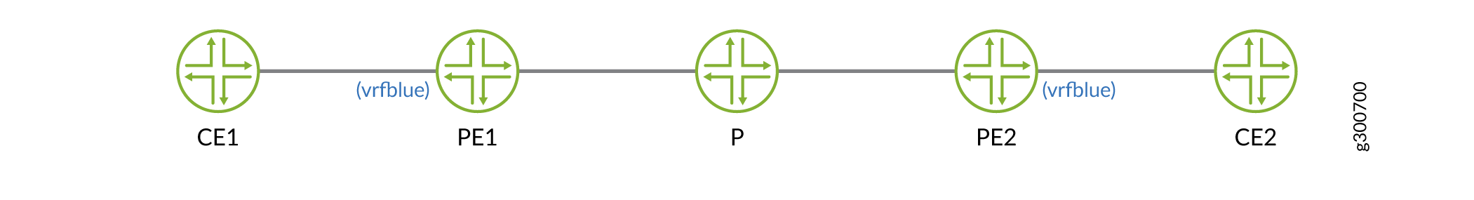
Example: Configure Layer 3 VPN (VRF) on cRPD Instance
This example shows the VPNv4 route resolution on PE routers and route reflectors by configuring the PE routers with specific policies to control the import of routes into and the export of routes from the VRF table and with next hops learnt using BGP labeled unicast. In this example, the traffic flows from CE1 to CE2.
Requirements
This example uses the following hardware and software components:
-
Ubuntu software version 18.04
-
Linux kernel version 4.5 or later
-
cRPD software Release version 19.4R1 or later
Before you configure a Layer 3 VPN (VRF), you must install the basic components:
-
MPLS modules on the host OS on which the cRPD instance is created. For details, see Configure Settings on Host OS.
-
Provider edge router (PE1), a provider router (P), and provider edge router (PE2). For installing, see Install cRPD on Docker.
Overview
To configure the VPNv4 route resolution, you need to configure a routing instance of
type VRF for each VPN on each of the PE routers participating in the VPN and add
static routes to it. The static statement configures the static
routes that are installed in the vrfblue.inet.0 routing table.
There is no loopback interface or device for every VRF device created in the Linux
kernel. But the loopback host addresses are directly added to the VRF device which
can be learnt by RPD.
Configuration
- Configuring PE1 router with BGP LU
- Configuring P router with BGP LU
- Configuring PE2 router with BGP LU
Configuring PE1 router with BGP LU
Step-by-Step Procedure
The following example requires you to navigate various levels in the configuration hierarchy.
-
Create table mpls.0.
user@crpd1# set routing-options rib mpls.0 -
Configure policy that accepts routes.
[edit policy-options policy-statement] user@crpd1# set EXPORT_LO term 10 from route-filter 10.2.2.2/32 exact user@crpd1# set EXPORT_LO term 10 then accept user@crpd1# set NH_SELF term 10 then next-hop self -
Configure a VRF routing instance on PE1 and other routing instance parameters.
[edit routing-instances vrfblue] user@crpd1# set routing-options static route 10.1.1.1/32 next-hop 10.10.10.1 user@crpd1# set instance-type vrf user@crpd1# set route-distinguisher 100:100 user@crpd1# set vrf-target target:100:100 -
Configure the router ID.
user@crpd1# set routing-options router-id 10.2.2.2 -
Configure BGP session.
[edit protocols bgp group] user@crpd1# set underlay type external family inet unicast user@crpd1# set underlay type external export EXPORT_LO neighbor 10.20.20.3 family inet labeled-unicast resolve-vpn user@crpd1# set underlay type external export EXPORT_LO neighbor 10.20.20.3 peer-as 65002 local-as 65001 user@crpd1# set VPN type internal local-address 10.2.2.2 family inet-vpn unicast user@crpd1# set VPN local-as 65005 user@crpd1# set VPN neighbor 10.4.4.4 family inet-vpn unicast -
Configure the interface on MPLS.
user@crpd1# set protocols mpls interface all
Results
From configuration mode, confirm your configuration by entering the
show protocols bgp and show
routing-instances commands. If the output does not display the
intended configuration, repeat the configuration instructions in this
example to correct it.
user@crpd1# show routing-instances
vrfblue {
    routing-options {
        static {
            route 10.1.1.1/32 next-hop 10.10.10.1;
        }
    }
    instance-type vrf;
    route-distinguisher 100:100;
    vrf-target target:100:100;
}
user@crpd1# show protocols bgp
group underlay {
    type external;
    family inet {
        unicast;
    }
    export EXPORT_LO;
    neighbor 10.20.20.3 {
        family inet {
            labeled-unicast {
                resolve-vpn;
            }
        }
        peer-as 65002;
        local-as 65001;
    }
    neighbor 10.20.20.2 {
        family inet {
            labeled-unicast {
                resolve-vpn;
            }
        }
        peer-as 65001;
        local-as 65002;
    }
    neighbor 10.30.30.4 {
        family inet {
            labeled-unicast {
                resolve-vpn;
            }
        }
        peer-as 65003;
        local-as 65004;
    }
}
group VPN {
    type internal;
    local-address 10.2.2.2;
    family inet-vpn {
        unicast;
    }
    local-as 65005;
    neighbor 10.4.4.4 {
        family inet-vpn {
            unicast;
        }
    }
}
If you are done configuring the device, enter commit from configuration mode.
Configuring P router with BGP LU
Step-by-Step Procedure
The following example requires you to navigate various levels in the configuration hierarchy.
-
Create table mpls.0.
user@crpd2# set routing-options rib mpls.0 -
Configure policy that accepts routes.
[edit policy-options policy-statement] user@crpd2# set EXPORT_LO term 10 from route-filter 10.3.3.3/32 exact user@crpd2# set EXPORT_LO term 10 then accept user@crpd2# set NH_SELF term 10 then next-hop self -
Configure BGP session.
[edit protocols bgp group] user@crpd2# set underlay type external export EXPORT_LO neighbor 10.20.20.2 family inet labeled-unicast resolve-vpn user@crpd2# set underlay type external export EXPORT_LO neighbor 10.20.20.2 peer-as 65001 user@crpd2# set underlay type external export EXPORT_LO neighbor 10.20.20.2 local-as 65002 user@crpd2# set underlay type external export EXPORT_LO neighbor 10.30.30.4 family inet labeled-unicast resolve-vpn user@crpd2# set underlay type external export EXPORT_LO neighbor 10.30.30.4 peer-as 65003 user@crpd2# set underlay type external export EXPORT_LO neighbor 10.30.30.4 local-as 65004 -
Configure the router ID.
user@crpd2# set routing-options router-id 10.3.3.3 -
Configure the interface on MPLS.
user@crpd2# set protocols mpls interface all
Results
From configuration mode, confirm your configuration by entering the
show protocols bgp and show
policy-options commands. If the output does not display the
intended configuration, repeat the instructions in this example to correct
the configuration.
user@crpd2# show protocols bgp
group underlay {
    type external;
    export EXPORT_LO;
    neighbor 10.20.20.2 {
        family inet {
            labeled-unicast {
                resolve-vpn;
            }
        }
        peer-as 65001;
        local-as 65002;
    }
    neighbor 10.30.30.4 {
        family inet {
            labeled-unicast {
                resolve-vpn;
            }
        }
        peer-as 65003;
        local-as 65004;
    }
}
user@crpd2# show policy-options
policy-statement EXPORT_LO {
    term 10 {
        from {
            route-filter 10.3.3.3/32 exact;
        }
        then accept;
    }
}
policy-statement NH_SELF {
    term 10 {
        then {
            next-hop self;
        }
    }
}
Configuring PE2 router with BGP LU
Step-by-Step Procedure
The following example requires you to navigate various levels in the configuration hierarchy.
-
Create table mpls.0.
user@crpd3# set routing-options rib mpls.0 -
Configure policy that accepts routes.
[edit policy-options policy-statement] user@crpd3# set EXPORT_LO term 10 from route-filter 10.4.4.4/32 exact user@crpd3# set EXPORT_LO term 10 then accept user@crpd3# set NH_SELF term 10 then next-hop self -
Configure a VRF routing instance on PE2 and other routing instance parameters.
[edit routing-instances vrfblue] user@crpd3# set routing-options static route 10.5.5.5/32 next-hop 10.40.40.5 user@crpd3# set instance-type vrf user@crpd3# set route-distinguisher 100:100 user@crpd3# set vrf-target target:100:100 user@crpd3# set interface all -
Configure BGP session.
[edit protocols bgp group] user@crpd3# set underlay type external export EXPORT_LO neighbor 10.30.30.3 family inet labeled-unicast resolve-vpn user@crpd3# set underlay type external export EXPORT_LO neighbor 10.30.30.3 peer-as 65004 user@crpd3# set underlay type external export EXPORT_LO neighbor 10.30.30.3 local-as 65003 user@crpd3# set VPN type internal local-address 10.4.4.4 family inet-vpn unicast user@crpd3# set VPN local-as 65005 user@crpd3# set VPN neighbor 10.2.2.2 family inet-vpn unicast -
Configure the router ID.
user@crpd3# set routing-options router-id 10.4.4.4 -
Configure the interface on MPLS.
user@crpd3# set protocols mpls interface all
Results
From configuration mode, confirm your configuration by entering the
show protocols bgp and show
routing-instances commands. If the output does not display the
intended configuration, repeat the instructions in this example to correct
the configuration.
user@crpd3# show protocols bgp
group underlay {
    export EXPORT_LO;
    neighbor 10.30.30.3 {
        family inet {
            labeled-unicast {
                resolve-vpn;
            }
        }
        peer-as 65004;
        local-as 65003;
    }
}
group VPN {
    type internal;
    local-address 10.4.4.4;
    family inet-vpn {
        unicast;
    }
    local-as 65005;
    neighbor 10.2.2.2 {
        family inet-vpn {
            unicast;
        }
    }
}
user@crpd3# show routing-instances
vrfblue {
    routing-options {
        static {
            route 10.5.5.5/32 next-hop 10.40.40.5;
        }
    }
    interface all;
    instance-type vrf;
    route-distinguisher 100:100;
    vrf-target target:100:100;
}
Verification
Verifying VPNv4 Resolution on PE1
Purpose
To verify VPNv4 routes on PE1:
Action
From operational mode, enter the show route table vrfblue.inet.0
10.5.5.5
command:
user@crpd1> show route table vrfblue.inet.0 10.5.5.5
vrfblue.inet.0: 7 destinations, 7 routes (7 active, 0 holddown, 0 hidden)
+ = Active Route, - = Last Active, * = Both

10.5.5.5/32         *[BGP/170] 00:00:14, localpref 100, from 10.4.4.4
                      AS path: I, validation-state: unverified
                    >  to 10.20.20.3 via pe1-p, Push 299808, Push 299792(top)
From operational mode, enter the show route table mpls.0
command:
user@crpd1> show route table mpls.0
mpls.0: 3 destinations, 3 routes (3 active, 0 holddown, 0 hidden)
+ = Active Route, - = Last Active, * = Both

299808             *[VPN/170] 00:01:45
                    >  to 10.10.10.1 via pe1-ce1, Pop
299808(S=0)        *[VPN/170] 00:01:45
                    >  to 10.10.10.1 via pe1-ce1, Pop
299824             *[VPN/170] 00:01:45
                       receive table vrfblue.inet.0, Pop
From bash mode, enter the ip route list table 5 5.5.5.5
command:
user@crpd1> ip route list table 5 10.5.5.5
10.5.5.5 encap mpls 299792/299808 via 10.20.20.3 dev pe1-p proto 22
From bash mode, enter the ip -f mpls route command:
user@crpd1> ip -f mpls route
299808 via inet 10.10.10.1 dev pe1-ce1 proto 22
Meaning
You can view PE1 has a route under vrfblue.inet.0 to CE2
which is learnt from PE2 with nexthop
10.4.4.4,
which is resolved using BGP LU from P router.
Verifying BGP LU on P
Purpose
To verify VPNv4 routes on P:
Action
From bash mode, enter the ip -f mpls route show command:
user@crpd2> ip -f mpls route show
299776 via inet 10.20.20.2 dev p-pe1 proto 22
299792 via inet 10.30.30.4 dev p-pe2 proto 22
From operational mode, enter the show route table mpls.0
command:
user@crpd2> show route table mpls.0
mpls.0: 8 destinations, 8 routes (8 active, 0 holddown, 0 hidden)
+ = Active Route, - = Last Active, * = Both

0                  *[MPLS/0] 01:40:42, metric 1
                       Receive
1                  *[MPLS/0] 01:40:42, metric 1
                       Receive
2                  *[MPLS/0] 01:40:42, metric 1
                       Receive
13                 *[MPLS/0] 01:40:42, metric 1
                       Receive
299776             *[VPN/170] 01:19:24
                    >  to 10.20.20.2 via p-pe1, Pop
299776(S=0)        *[ VPN/170] 01:19:24
                    >  to 10.20.20.2 via p-pe1, Pop
299792             *[VPN/170] 01:19:20
                    >  to 10.30.30.4 via p-pe2, Pop
299792(S=0)        *[VPN/170] 01:19:20
                    >  to 10.30.30.4 via p-pe2, Pop
Meaning
You can view the MPLS and VPN routes from P to PE1 and P to PE2.
Verifying VPNv4 Resolution on PE2
Purpose
To verify VPNv4 routes on PE2:
Action
From operational mode, enter the show route table vrfblue.inet.0
10.1.1.1
command:
user@crpd3> show route table vrfblue.inet.0 10.1.1.1
vrfblue.inet.0: 7 destinations, 7 routes (7 active, 0 holddown, 0 hidden)
+ = Active Route, - = Last Active, * = Both

10.1.1.1/32         *[BGP/170] 00:00:26, localpref 100, from 10.2.2.2
                      AS path: I, validation-state: unverified
                    >  to 10.30.30.3 via pe2-p, Push 299808, Push 299776(top)
From operational mode, enter the show route table mpls.0
command:
user@crpd3> show route table mpls.0
mpls.0: 7 destinations, 7 routes (7 active, 0 holddown, 0 hidden)
+ = Active Route, - = Last Active, * = Both

0                  *[MPLS/0] 01:34:39, metric 1
                       Receive
1                  *[MPLS/0] 01:34:39, metric 1
                       Receive
2                  *[MPLS/0] 01:34:39, metric 1
                       Receive
13                 *[MPLS/0] 01:34:39, metric 1
                       Receive
299808             *[VPN/170] 00:00:43
                    >  to 10.40.40.5 via pe2-ce2, Pop
299808(S=0)        *[VPN/170] 00:00:43
                    >  to 10.40.40.5 via pe2-ce2, Pop
299824             *[VPN/170] 00:00:43
                       receive table vrfblue.inet.0, Pop
From bash mode, enter the ip route list table 5
10.1.1.1
command:
user@crpd3> ip route list table 5 10.1.1.1
10.1.1.1 encap mpls 299776/299808 via 10.30.30.3 dev pe2-p proto 22
From bash mode, enter the ip -f mpls route command:
user@crpd3> ip -f mpls route
299808 via inet 10.40.40.5 dev pe2-ce2 proto 22
Meaning
On PE2 router, PE1 displays the routes for the VRF table
vrfblue.inet.0 using BGP LU about
10.1.1.1
as a VPNv4 prefix with nexthop as
10.2.2.2.