Configure Service Chaining With PNF
This section shows how to create Layer 3 PNF service chains for inter-LR traffic.
Service Chaining Using a PNF
Service Chaining provides security control and enforcement through a physical firewall on traffic between virtual networks that are attached to logical routers. By default, virtual networks attached to the same logical router can communicate only using Layer 3 routing. Virtual networks connected to different logical routers cannot communicate. Service chaining using a firewall (a physical network function) between the logical routers allows virtual networks on separate logical routers to communicate and to communicate in a secure way.
For CEM service chaining you insert a physical network function (PNF) device between two logical routers on a border spine or border leaf device. The PNF device allows for Layer 3 communication between the logical routers. Only Juniper SRX Services Gateways are supported as PNF devices.
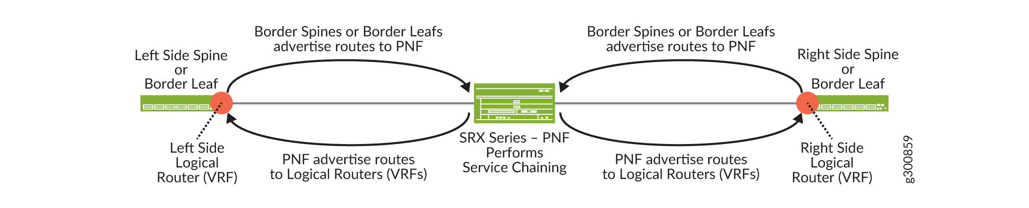
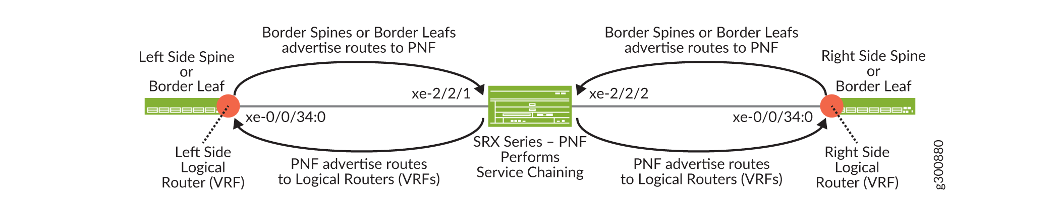
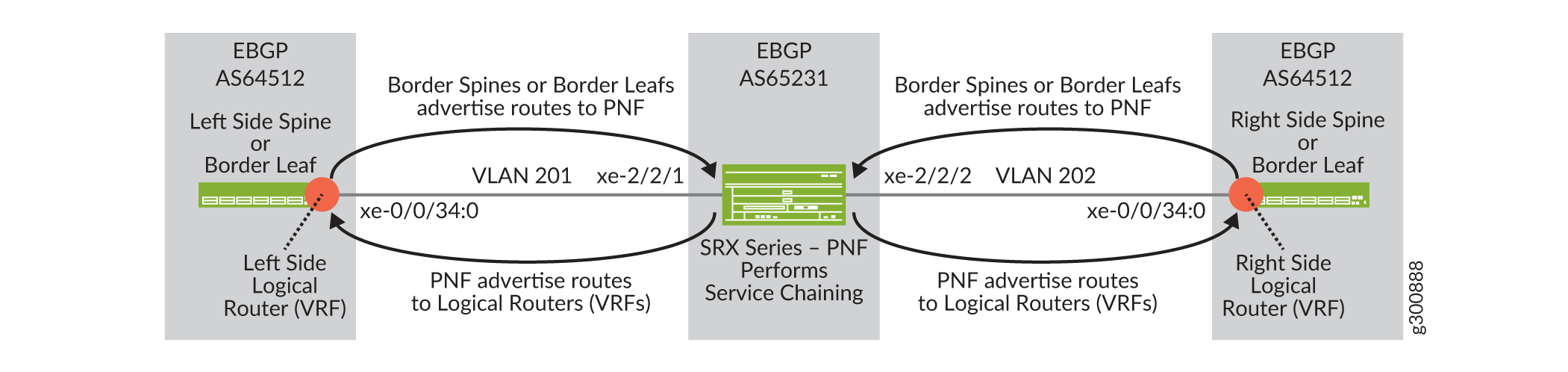
Figure 1 shows a logical view of service chaining. VLANs provide connectivity between the logical routers and the PNF device. EBGP advertises routes between the logical routers and the PNF.
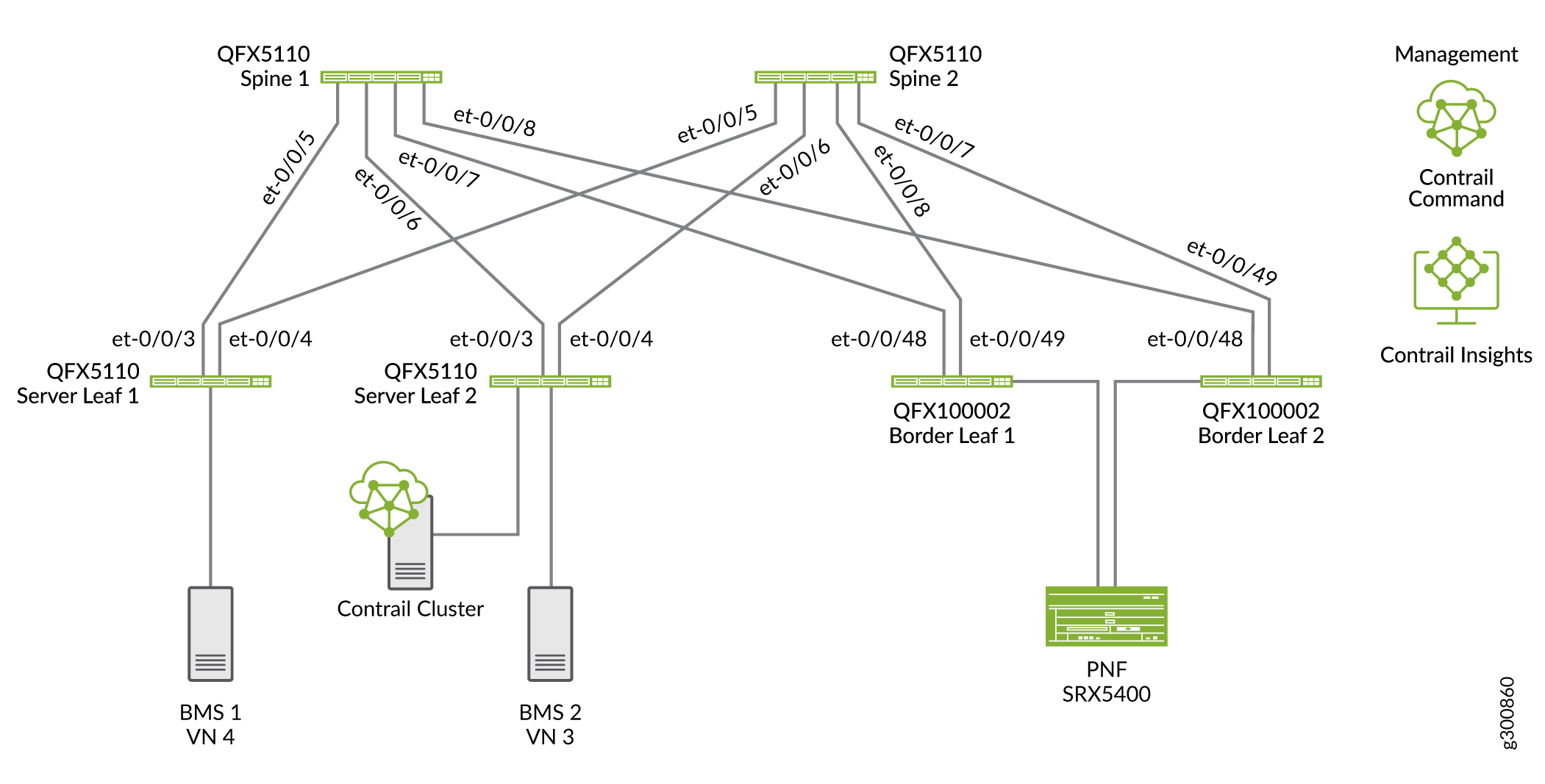
In a topology that uses border leaf devices, attach the PNF to the border leaf devices as shown in Figure 2.
Service Chaining Configuration Overview
In this example we are configuring service chaining In the following topology to provide inter-LR routing on the blue and green networks as shown in Figure 3. SRX4k and SRX5k Services Gateways are supported as managed PNFs. Our PNF is an SRX5400 Services Gateway.
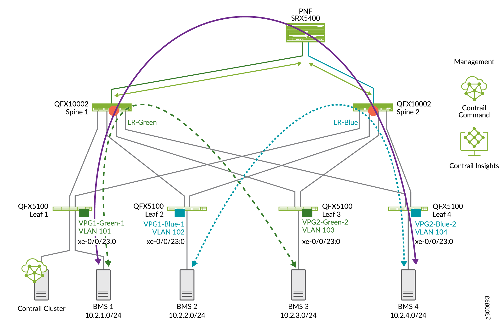
The virtual networks show in Figure 3 have already been configured. See Configure Virtual Networks for Multi-tenant Service Operations. We are adding PNF service chaining so that devices on each network can communicate with each other as shown with the purple line.
To configure service chaining for inter-LR traffic:
Onboard an SRX device as the PNF device connected to an existing fabric—you can connect the PNF device to a border spine or a border leaf.
Assign PNF service chaining device role to the PNF device and to the border spines or border leaf devices that connect to the PNF device.
Connect the PNF to the fabric using a PNF service template.
Connect the right and left LRs by configuring VLANs and EBGP peering between the PNF and the LRs using a PNF service instance.
Onboard an SRX Services Gateway as the PNF Device
This section shows how to use Contrail Command to integrate an SRX device into our data center fabric to serve as a PNF device.
This configuration assumes that you have already created your fabric. You must use the Brownfield Wizard to onboard the PNF device. You can’t onboard a PNF using the Greenfield Wizard.
SRX clusters are not supported for PNF service chaining.
To selectively onboard an SRX Series router as a PNF device onto an existing fabric:
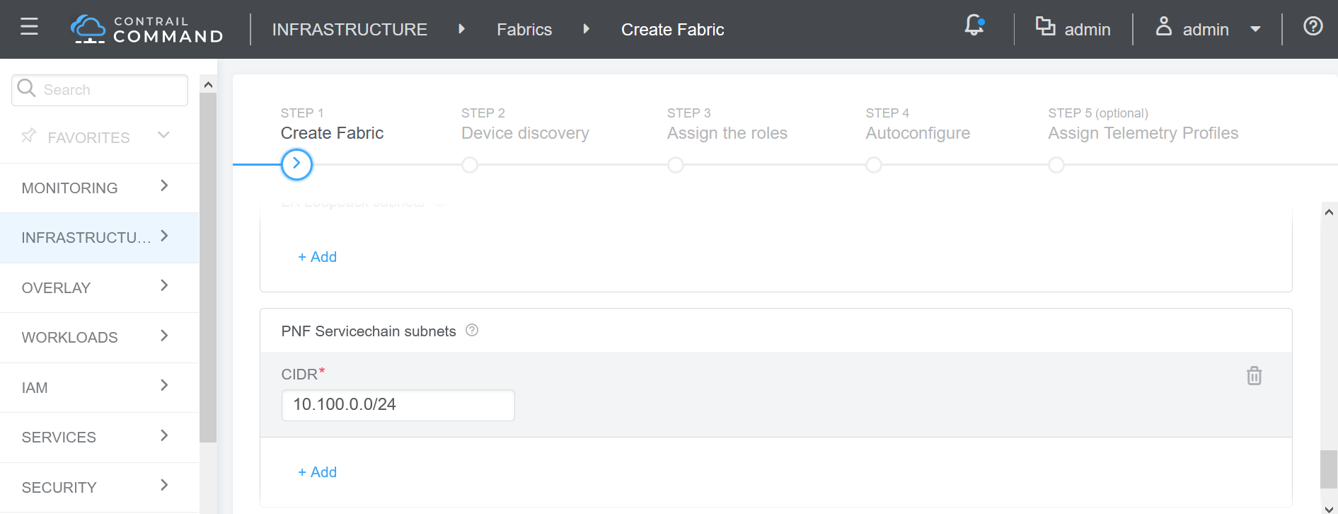
- On the Create Fabric screen, configure the Management
subnet, then select Additional Configuration, and enter the PNF ServiceChain
subnets.
In this example, we are assigning 10.1.1.15/32 as the Management subnet and 10.100.0.0/24 as the PNF ServiceChain subnet. The Management subnet searches for the device. The PNF ServiceChain subnet establishes the EBGP session between the PNF device and the spine.
Name
DC1
Overlay ASN
64532
Node Profile
Select the SRX device
VLAN-ID Fabric-Wide Significance
Check box
Management subnets
(used to search for the device)
10.1.1.15
PNF ServiceChain subnets (subnet used to establish EBGP session between the PNF device and the spine)
10.200.0.0/24
Assign Device Roles for the PNF Device
In this procedure we will assign the PNF service chaining role for the spine or border leaf devices that connect to the PNF.
To assign roles:
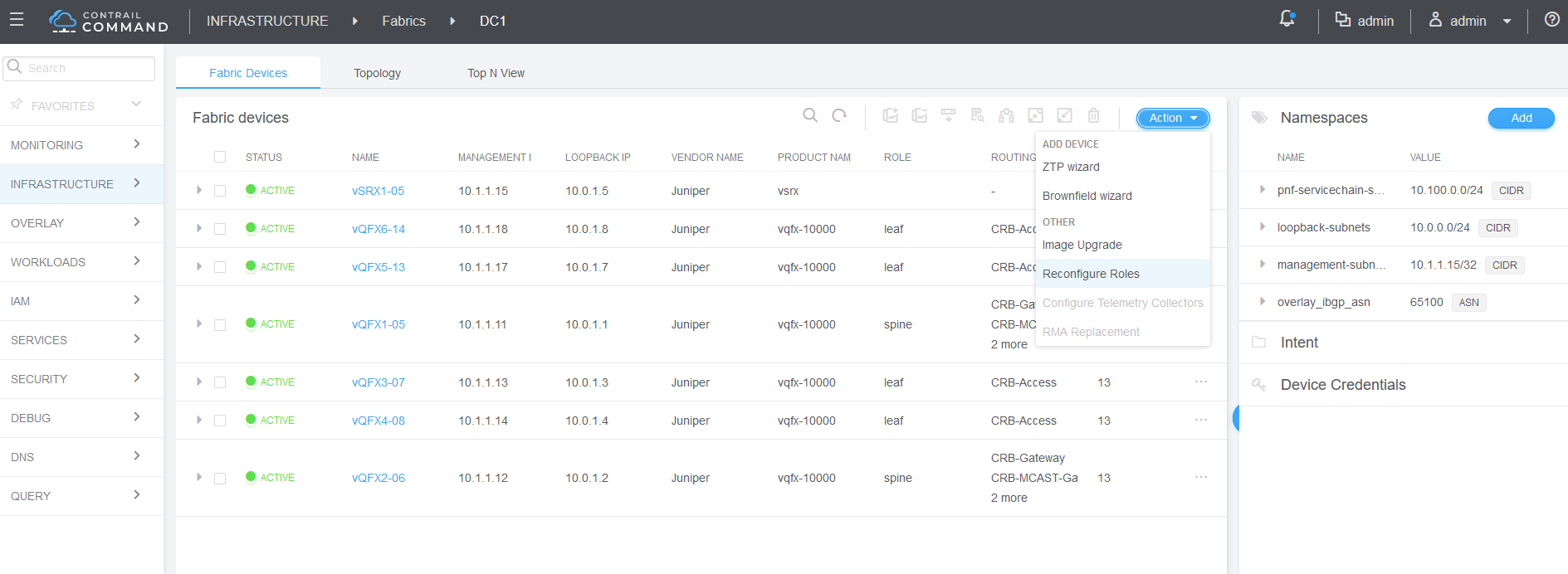
- On the Fabric Devices summary screen, select
the PNF device, and then select Action>Reconfigure
Roles.
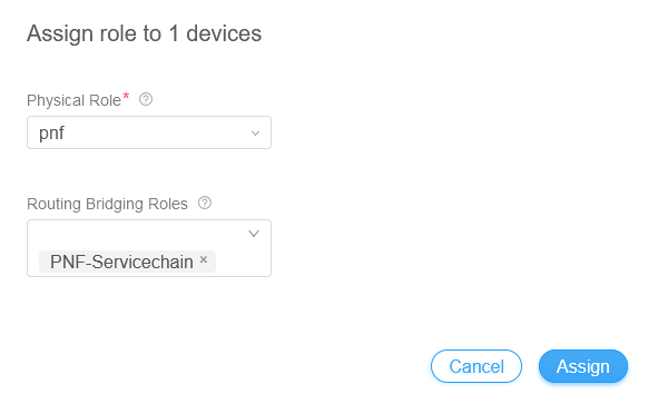
- Next to the PNF device, select Assign Roles.
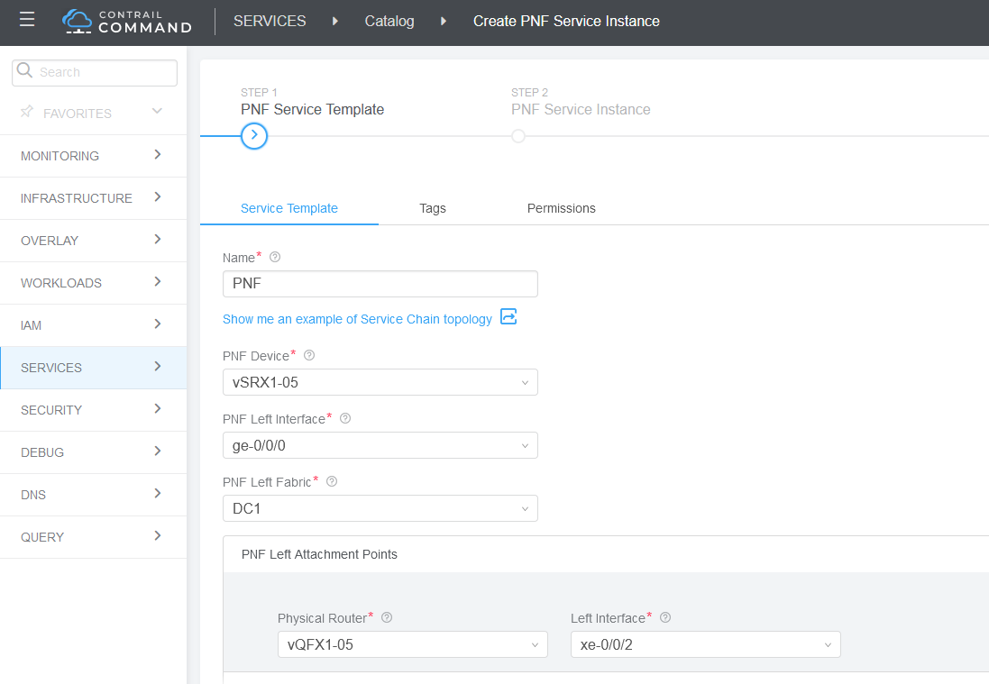
Create a PNF Service Template
The service template provides Contrail Command with information about how the PNF device attaches to the spine or border leaf device. In our example, we are using the following interface numbers:
To create a PNF service template:
- Click Create and select Instance (with
Template) from the list that appears.
A PNF service instance defines how logical routers are interconnected and how BGP reachability is exchanged between the PNF and the logical routers. The configuration includes VLANs that are created between the PNF and the logical routers along with EBGP peering.
To create a PNF Service Instance:
Navigate to Services > Deployments, and select the PNF tab.
The PNF Service Instances screen displays.
Select Create Instance.
Configure the screen as shown here:
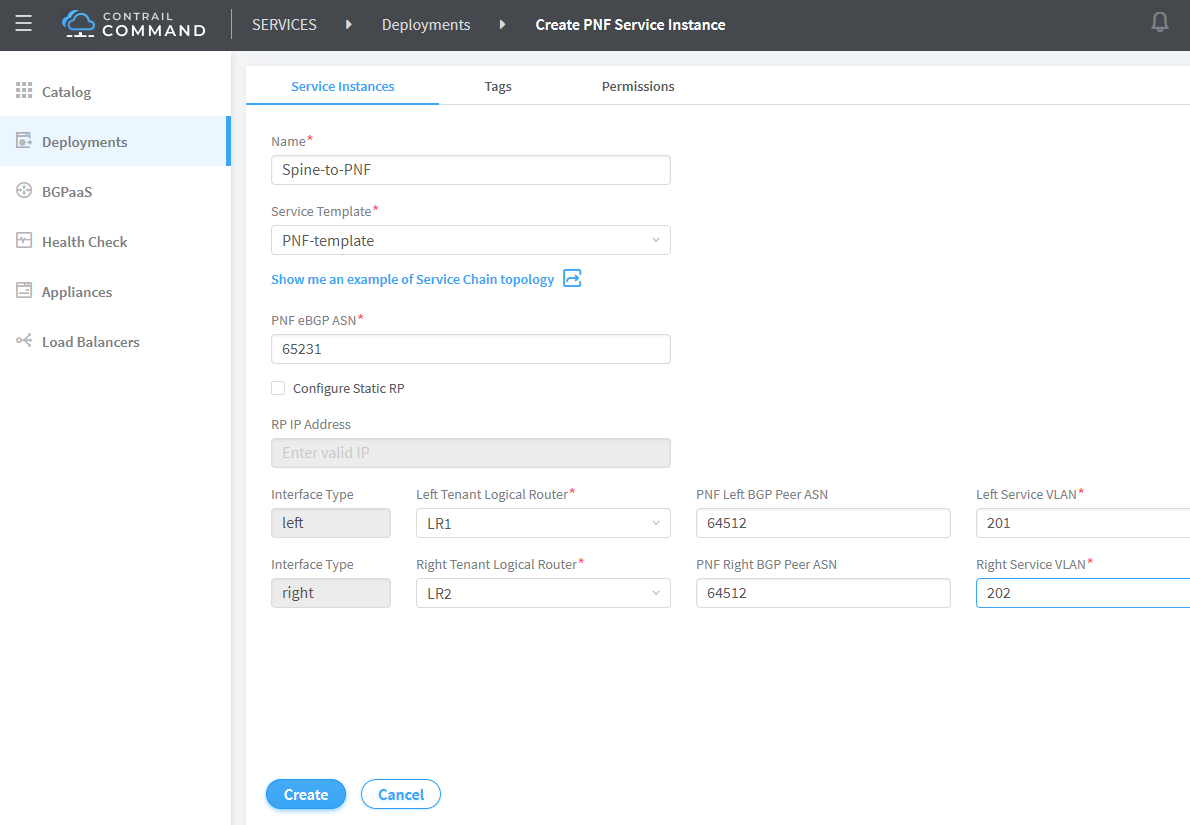
Enter the following information in the PNF Service Template pane and click Create.
Field
Value
Name
Spine-to-PNF
Service Template
PNF-template
PNF eBGP ASN
65231
Left Tenant Logical Router
LR1-Green
PNF Left BGP Peer ASN
64512
Left Service VLAN (VLAN between the PNF and the LR1)
201
Right Tenant Logical Router
LR2-Green
Right BGP Peer ASN
64512
Right Service VLAN (VLAN between the PNF and LR2)
202