Help us improve your experience.

Let us know what you think.

Do you have time for a two-minute survey?


Set Up a PNF Service Chain

SUMMARY In this section, you are creating a path between the two overlay segmented networks by connecting them through an SRX firewall. You insert the firewall by setting up a service chain that includes the firewall.

Explanation of Procedure

A physical network function (PNF) service chain inserts a PNF device such as an SRX firewall between two segmented networks. The overlay you created previously consists of two segmented networks that have no logical connectivity to each other. When you add a PNF service chain, you are effectively connecting the two segmented networks through a firewall that enforces policies to govern what traffic can pass from one network to the other.

The PNF device exchanges routes with the logical routers over eBGP. It learns routes from one logical router and advertises them to the other logical router.

The first step to creating a service chain is to onboard the SRX. You do this by invoking the same Create Fabric wizard you used earlier, but this time you’re discovering an existing (brownfield, already configured) device. After you onboard the SRX, you can then logically insert the SRX between the two segmented networks.

Onboard the PNF Device

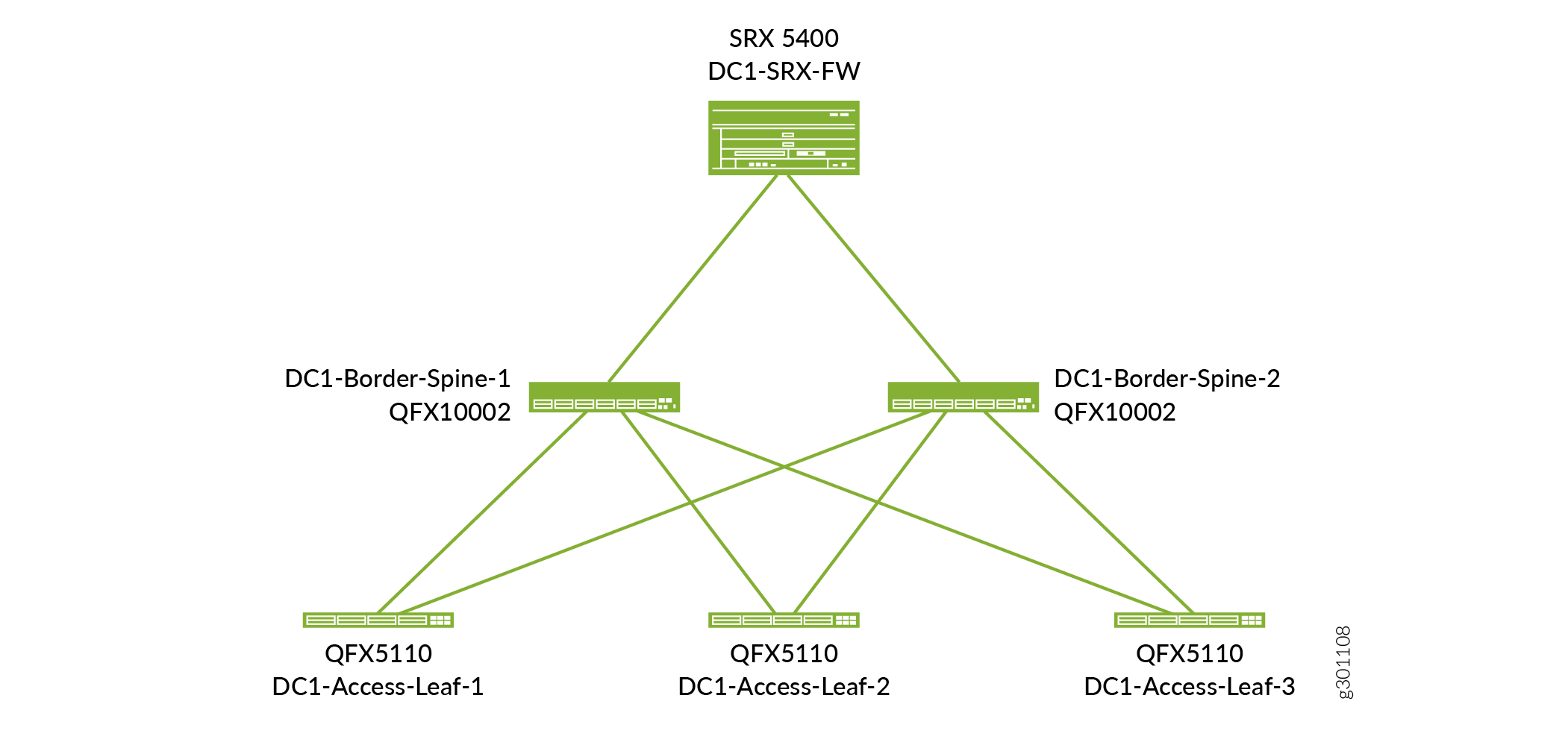
Before you start, physically connect the SRX to the spine switches as shown in Figure 1. The SRX in this use case is already up and running and has a hostname DC1-SRX-FW. By onboarding this device, you are telling Contrail Networking to add this device to the fabric. Contrail Networking then configures the fabric port IP addresses on the SRX and the fabric port IP addresses on the spine switches.

Figure 1: PNF Physical View PNF Physical View
  1. Select INFRASTRUCTURE>Fabrics and click on the DC1-Fabric that you created previously.

    The Fabric devices window appears listing all the devices in the DC1-Fabric.

  2. Select Action>Brownfield wizard.

    The Create Fabric wizard is launched, but you are not creating a fabric in this procedure. You are using the wizard to add a PNF device to the fabric you created earlier.

  3. Fill in the fields on this page as shown in Table 1. Since this is an existing SRX, all you need to do is supply the login credentials and the management IP address. Leave all other fields at their defaults.
    Table 1: Fields in the Create Fabric Page

    Fields

    Meaning

    Setting in this Example

    Device credentials>Username

    The username to log in to the device.

    <existing-username>

    Device credentials>Password

    The password to log in to the device.

    <existing-password>

    Management subnets>CIDR

    The IP address of the device on the management network.

    192.168.1.147/32

    This is the existing IP address of the device.

    Management subnets>Gateway

    The gateway (if it exists).

    Delete the recommended gateway and leave blank.

    Click Next to launch the device discovery process.

  4. After Contrail Networking finishes device discovery, click Next to progress to role assignment.
  5. Select the row for the PNF device you just discovered and click the Assign Role icon on the far right of the row.

    The Assign role to devices window appears.

  6. Set the role for the SRX as shown in Table 2 and click Assign.
    Table 2: DC1-Access-Leaf-3 Roles

    Role

    Setting in this Example

    Physical

    pnf

    Routing Bridging Roles

    PNF-Servicechain

  7. Click Autoconfigure to start auto-configuration.
  8. When auto-configuration is complete, click Next and then click Finish to skip the assignment of telemetry profiles.

You have now onboarded the SRX and can now proceed to creating the service chain.

Create PNF Service Chain

In order to create the service chain, you first create a template that describes how the PNF device is connected to the fabric. The PNF device can be reused for multiple overlay applications. Creating a template saves you from configuring this information for future service chains.

  1. Select SERVICES>Catalog to bring up the Catalog page.
  2. Click the PNF tab to bring up the PNF Service Templates window and click Create>Template.

    The Create PNF Service Template page appears.

  3. Fill in the fields on this page as shown in Table 3.
    Table 3: PNF Service Template

    Field

    Meaning

    Setting in this Example

    Name

    The name you want to call this service template.

    DC1-SRX5400

    PNF Device

    The name of the device. This is the existing pre-configured hostname of the SRX.

    DC1-SRX-FW

    PNF Left Interface

    The interface on one side of the SRX.

    et-1/2/0

    PNF Left Fabric

    The name of the fabric on one side of the SRX.

    DC1-Fabric

    PNF Left Attachment Points>Physical Router

    The router attached to the left interface of the SRX.

    DC1-Border-Spine-1

    PNF Left Attachment Points>Left Interface

    The interface on the router attached to the left interface of the SRX.

    et-0/0/3

    PNF Right Interface

    The interface on the other side of the SRX.

    et-1/2/1

    PNF Right Fabric

    The name of the fabric on the other side of the SRX.

    DC1-Fabric

    PNF Right Attachment Points>Physical Router

    The router attached to the right interface of the SRX.

    DC1-Border-Spine-2

    PNF Right Attachment Points>Right Interface

    The interface on the router attached to the right interface of the SRX.

    et-0/0/3

    Click Create to create the template called DC1-SRX5400-template. Now you can create the service chain instance that uses this template in the next few steps.

  4. Select SERVICES>Deployments to bring up the Deployments page.
  5. Click the PNF tab to bring up the PNF Service Instances window and click Create>Instance.

    The Create PNF Service Instance page appears.

  6. Fill in the fields on this page as shown in Table 4.
    Table 4: Create PNF Service Instance

    Fields

    Meaning

    Setting in this Example

    Name

    The name you want to call this service chain instance.

    Web-To-DB

    Service Template

    The service template you want to use. This is the name of the service template you created earlier.

    DC1-SRX5400-template

    PNF eBGP ASN

    The ASN for the PNF device. This is used by eBGP to exchange routes in the overlay.

    65100

    Left Tenant Logical Router

    The logical router attached to the left interface.

    This assignment is arbitrary since each spine switch has the same two logical routers instantiated.

    Web-LR

    PNF Left BGP Peer ASN

    The ASN for the left overlay network. There is one ASN for the entire overlay.

    65000

    Left Service VLAN

    The VLAN ID for the left interface.

    1001

    Right Tenant Logical Router

    The logical router attached to the right interface. This is the other logical router.

    DB-LR

    PNF Right BGP Peer ASN

    The ASN for the right overlay network. There is one ASN for the entire overlay.

    65000

    Right Service VLAN

    The VLAN ID for the right interface.

    1002

    When you finish filling in the fields, click Create.

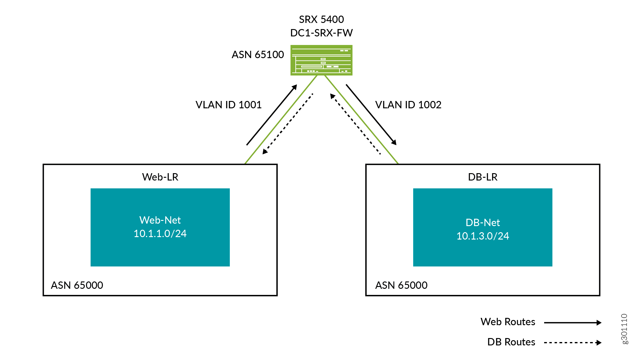
You have now created the service chain. Routes between the two segmented networks are now exchanged, and inter-network traffic can now traverse the SRX. By default, Contrail Networking configures the SRX to be permissive (that is, an <any>-<any>-<any> permit policy). To change the policy, log in to the SRX and configure the policy as you normally do.

Figure 2 shows the physical connectivity of the SRX in the network. Note that typically you would have multiple SRX devices for redundancy and routing efficiency.

Figure 2: PNF Physical View After ConfigurationPNF Physical View After Configuration

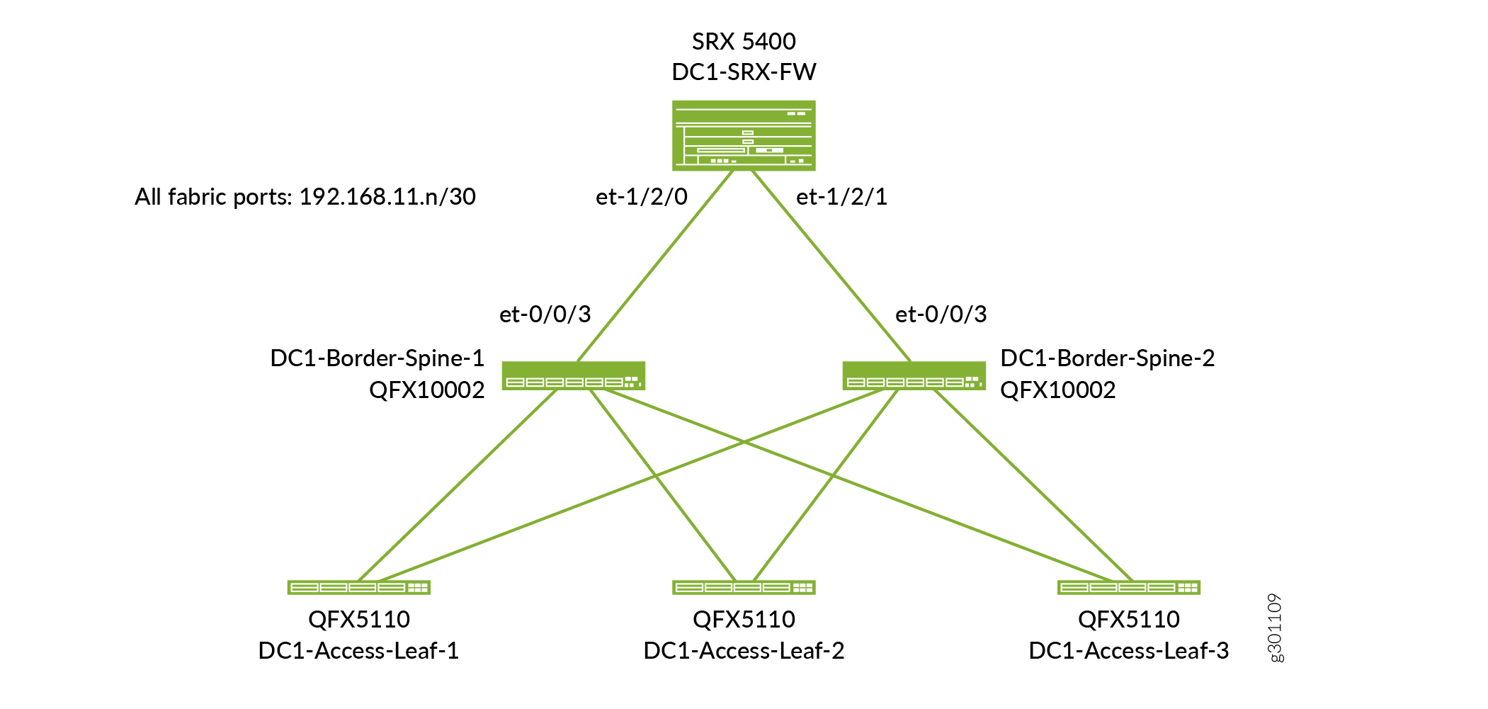
Figure 3 shows the SRX in the overlay. Routes from one segmented network are advertised across to the other segmented network through the firewall.

Figure 3: PNF Logical View After ConfigurationPNF Logical View After Configuration