Create the Overlay Networks
SUMMARY In this section, you are creating the overlay segmented networks on top of the physical fabric underlay.
Explanation of Procedure
With the fabric onboarded, you can route traffic from any device to any device, which is what you want for the physical network. You are now ready to create the logical networks that ride on top of this physical network. These are the overlay segmented networks that dictate which endpoint device can communicate with which other endpoint device. For example, you may want to create a segmented network for your finance department, another for your regular employee intranet, and yet another for your third-party contractors.
Creating overlay segmented networks, however, can be confusing especially if you’re working with CLIs that don’t explicitly distinguish between underlay and overlay parameters. Running the same routing protocols in both the underlay and the overlay, as is common in many data centers, can certainly add to the confusion.
Although you still need to know the difference between the underlay and the overlay, Contrail Command provides you with a simple user interface to create overlay segmented networks without requiring you to work with the corresponding underlay and overlay CLI commands. As with the underlay fabric, you work with the overlay segmented network as a whole rather than with each individual switch.
In order to minimize confusion between underlay (physical) and overlay (logical) terminology, Contrail Networking uses different terms for the overlay (Table 1).
This document refers to a segmented network as a segregated network in general and not necessarily as a single LAN segment or VLAN. In other words, a segmented network can consist of multiple VLANs and multiple subnets. A segmented network can only communicate with another segmented network through a security policy.
Contrail Networking was designed to serve both the enterprise (single-tenant) and service provider (multi-tenant) markets. To a new user of Contrail Networking, this flexibility can sometimes be confusing. To minimize confusion, this table explains the terminology in the context of a single-tenant network. The application of these concepts to multi-tenant networks may differ. In other words, Contrail Networking is a tool that allows you to abstract your network in different ways. How you abstract an enterprise network may be different from how you abstract a service provider network.
Overlay Term |
Meaning |
|---|---|
Virtual network |
A virtual network is an overlay bridged network. An endpoint device attached to a virtual network has layer 2 reachability to any other endpoint device attached to the same virtual network regardless of which physical (underlay) LAN the device resides on. Typically, a virtual network has a single subnet, but Contrail Networking allows you to define a virtual network with multiple subnets, which is akin to having a physical LAN or VLAN supporting secondary IP addressing. |
Logical router |
A logical router is analogous to a VRF or routing instance and performs routing for a single segmented network. A segmented network consists of one or more virtual networks. In other words, a logical router can bridge and route within and between the virtual networks it is connected to. It cannot route to unconnected virtual networks, which are other segmented networks. You will learn how to route between segmented networks in a later step. The segmented network can have a single subnet or multiple subnets depending on whether you configure the logical router to route for one or more virtual networks. The same logical router is instantiated on every physical device that acts as a router in the overlay. In a centrally-routed model, these are the spine switches. In an edge-routed model, these are the leaf switches. |
Virtual port group |
A virtual port group allows you to multi-home your BMS or VM endpoints and consists of one or more switch ports grouped together and presented to the virtual network as a single entity, similar to a LAG or MC-LAG. For consistency, Contrail Networking requires an endpoint BMS or VM to attach to the virtual network through a virtual port group even if the attachment point is a single port, in which case the virtual port group consists of a single member. |
Figure 1 shows the relationship between logical routers and virtual networks for a single-tenant network. A physical router can have multiple logical routers. Each logical router contains routes for a single segmented network, which is represented by one or more virtual networks. Each virtual network has a single subnet (typically) and attaches to endpoint devices through virtual port groups.
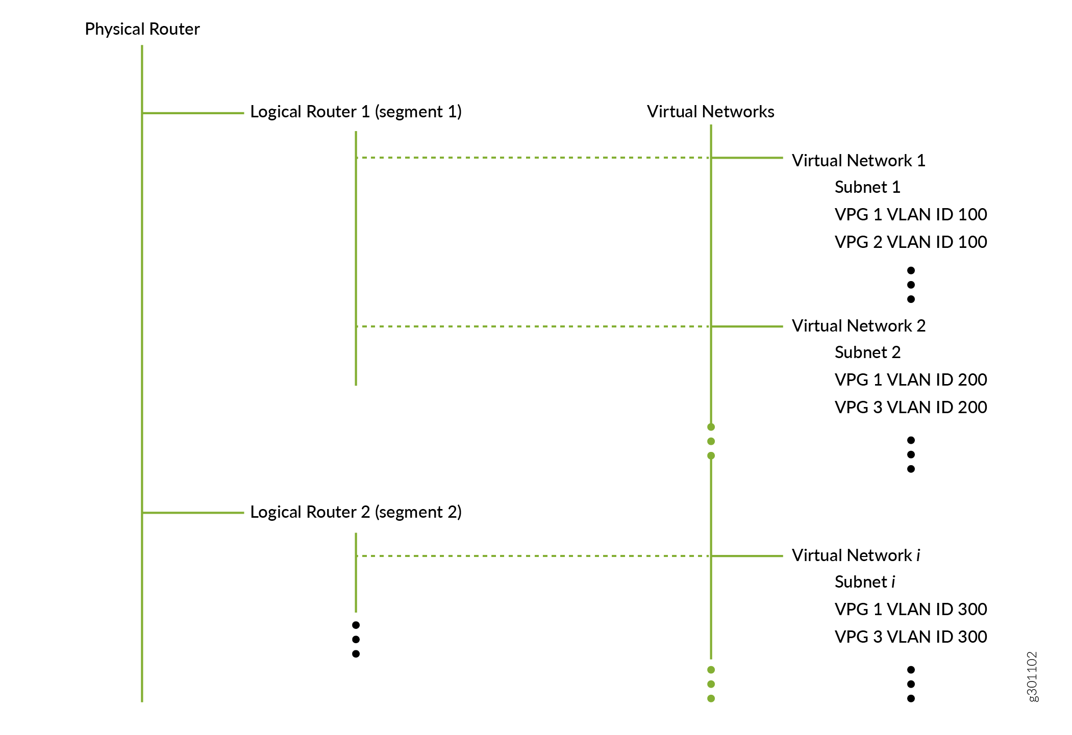
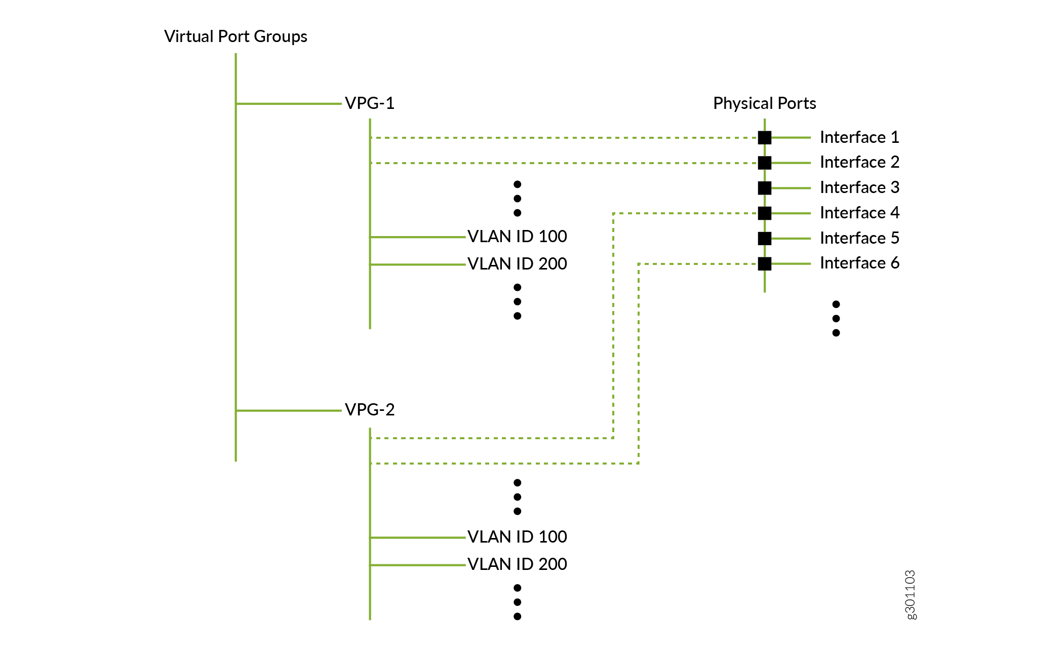
Figure 2 shows the relationship between virtual port groups and physical interfaces. A virtual port group consists of one or more associations with physical interfaces and can be defined with VLANs.
A number of observations can be made from the relationships shown for a single-tenant network:
Endpoint devices (attached to a virtual port group) in virtual network 1 can freely communicate with endpoint devices in virtual network 2 because both of these virtual networks are connected to the same logical router. However, endpoint devices in virtual network 1 cannot communicate with endpoint devices in virtual network i unless you explicitly allow it because these virtual networks are connected to different logical routers.
While a logical router can connect to multiple virtual networks, the reverse is not true. Just as a LAN can only belong to a single VRF, a virtual network can only connect to a single logical router. In the hierarchy above, since virtual network 1 is connected to logical router 1, it cannot also be connected to logical router 2.
Furthermore, Contrail Networking allows you to define the scope of your VLANs and IP addresses. For enterprises, it is common for your VLANs and IP addresses to have enterprise-wide significance. For example, all devices using VLAN ID 100 are on the same VLAN even if they attach to different virtual port groups, and all IP addresses are unique even if they belong to different logical routers (routing instances).
Finally, when you create the overlay segmented networks, you have the option of defining a centrally-routed architecture or an edge-routed architecture:
In a centrally-routed architecture, the spine switches perform the VXLAN routing. All user traffic is encapsulated and sent through VXLAN tunnels that terminate on the spine switches. The spine switches decapsulate and route packets based on the inner overlay IP header.
In an edge-routed architecture, the leaf switches perform the VXLAN routing. The leaf switches decapsulate and route packets based on the inner overlay IP header.
To illustrate these concepts, this use case creates two overlay segmented networks and uses a centrally-routed model where each spine switch performs the routing. To do this, you define two virtual networks, one for each segmented network. Next, you define the logical routers that connect to these virtual networks and instantiate the logical routers onto the physical spine switches. Each spine switch therefore has two logical routers, with each logical router responsible for its own segmented network. You then create virtual port groups that you attach to the virtual networks.
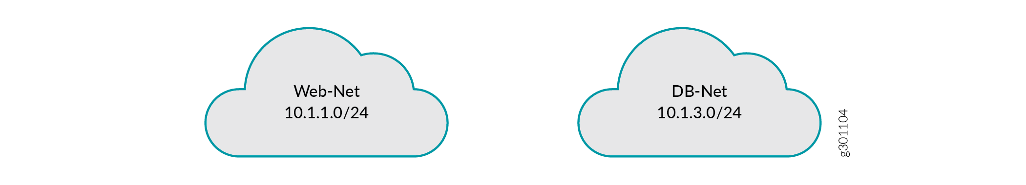
Create Virtual Networks
You have now created the two virtual networks, each with a single subnet (Figure 3). These virtual networks are not associated with any physical devices yet.
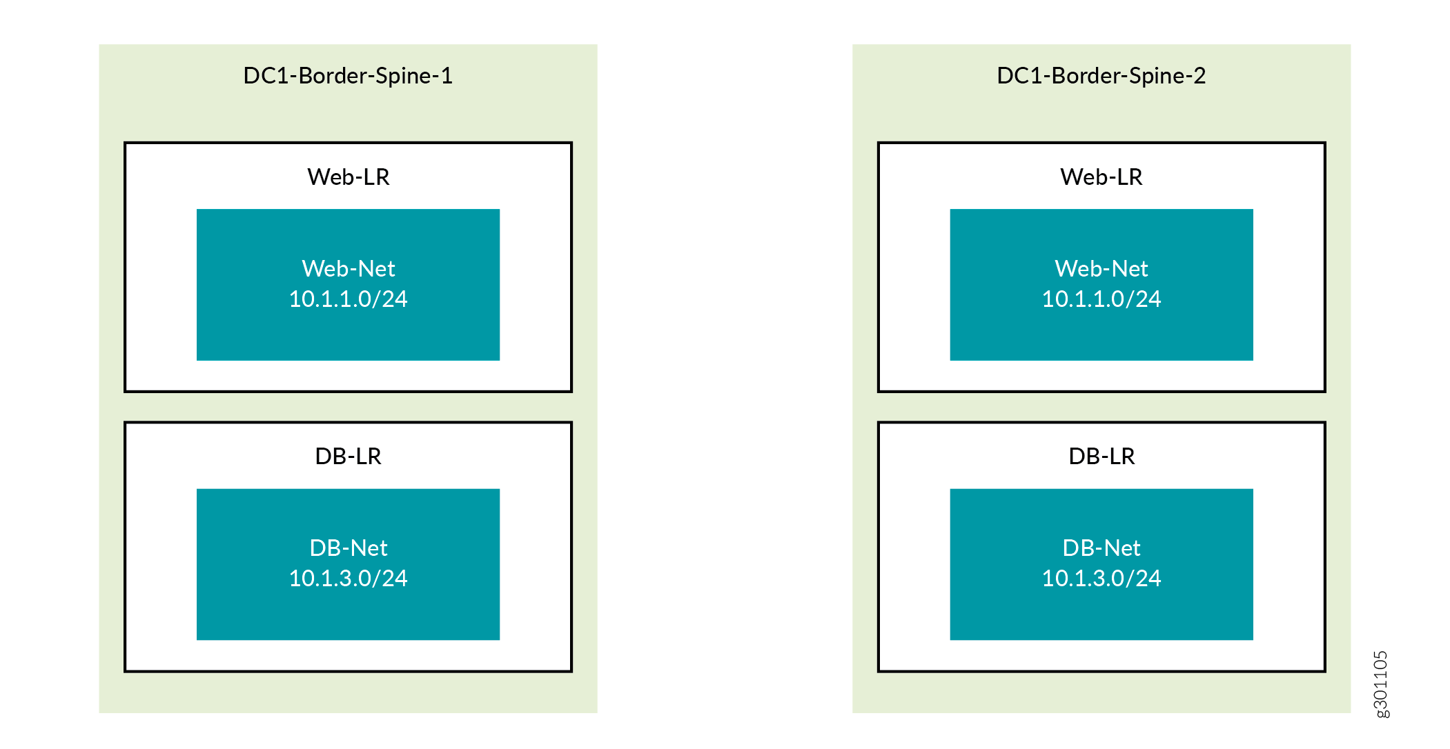
Create Logical Routers
You have now created two logical routers and instantiated them on both border spine routers. You have also associated each logical router with one of the virtual networks you created in the previous procedure. Figure 4 shows logical router Web-LR instantiated on both spine switches and providing routing for the Web-Net virtual network and logical router DB-LR instantiated on both spine switches and providing routing for the DB-Net virtual network.
Create Virtual Port Groups
A virtual port group is a network entity (not a server entity) and is the sole means by which you attach a port to a virtual network. It provides a consistent attachment point regardless of whether you are attaching a single port or a port group. Members of the group can be from the same switch or from across switches such as in a multi-homed configuration.
You have now created two virtual port groups, one connecting to each virtual network.
Figure 5 and Figure 6 show the VPGs from the physical and logical perspective respectively. For context, these figures show the endpoint servers (compute devices), which have been configured outside of this use case.
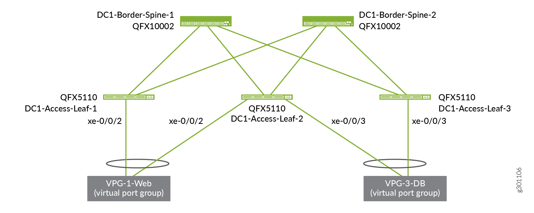
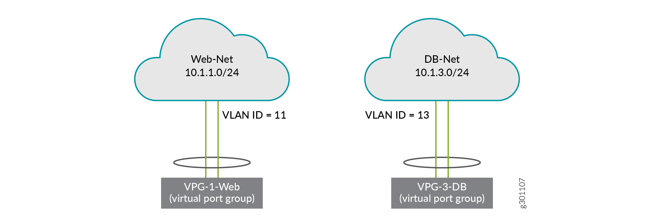
Now that you have created both segmented networks, endpoints on each segmented network have full connectivity within their respective network, but no connectivity to endpoints on the other segmented network. If that meets your needs, then you are done. If, however, you want to allow communication between the two segmented networks, then you need to set up a PNF service chain, which is the next step in this use case.
Verify Routing Tables on the Spine Switch (Optional)
You can see how the overlay routes (10.1.1.0/24 and 10.1.3.0/24) map onto the underlay (192.168.11.13, 192.168.11.17, 192.168.11.21).