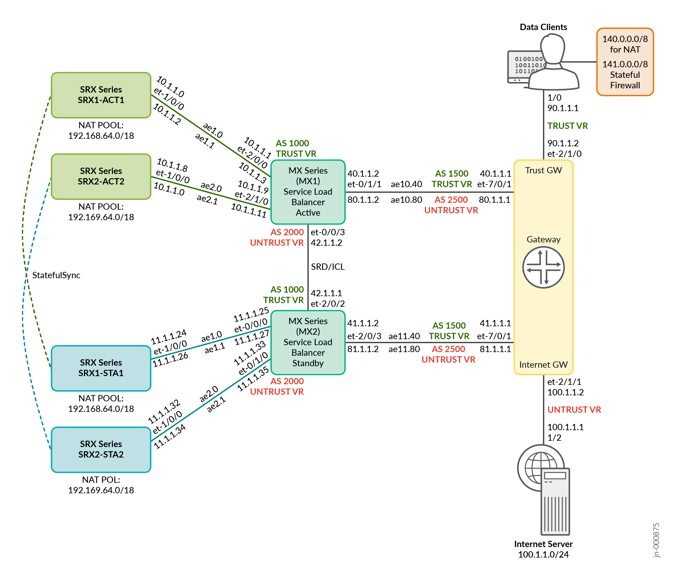
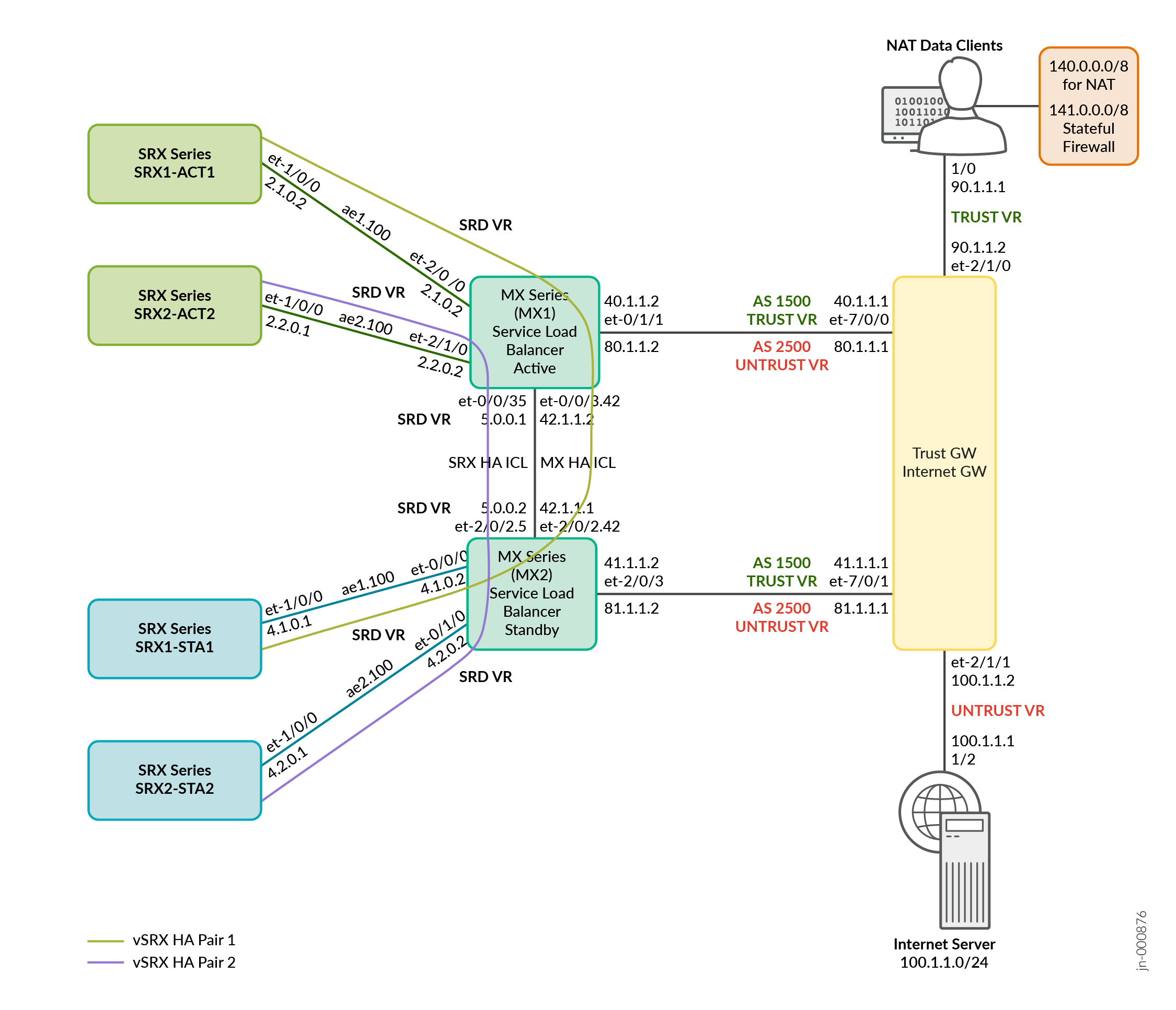
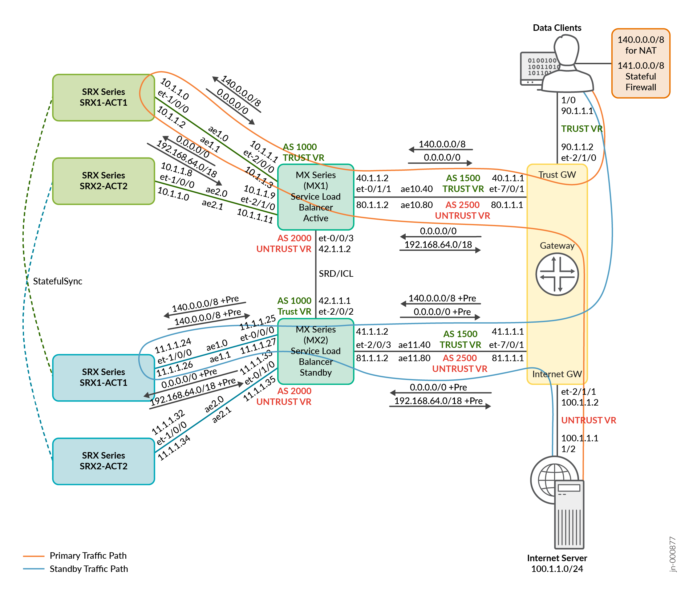
Example: Dual MX Series (ECMP Based Consistent Hashing) and Scaled-Out SRX Series Firewalls (Multinode HA) for NAT and Stateful Firewall
In this configuration, you’ll learn to set up a dual MX Series with scaled-out SRX Series Firewalls in Multinode HA mode for NAT and stateful firewall services.
Overview
Table 1 shows the deployment components used in the example.
| CSDS Components | Details |
|---|---|
| Forwarding Layer | MX304 with Junos OS Release 23.4R1 or later |
| Services Layer | vSRX 3.0 with Junos OS Release 23.4R1 or later |
| Redundancy |
Dual MX Series in Active/Standby (SRD) for redundancy and ECMP based Consistent Hashing for load balancing. SRX Series Firewalls in Multinode HA (Active/Backup) and session synchronization. |
| Features | NAPT44 and stateful firewall (IPv4 Support) |
| Additional Component | Gateway router for TRUST and UNTRUST networks. The example uses MX Series. You can use any device. |
See Table 2 and Table 3 for traffic flow in Multinode HA pairs.
| Feature | Traffic Flow Component | IP Address and Port Number |
|---|---|---|
|
NAPT44 on SRX Series Firewalls for MNHA Pair 1 (SRX1-ACT1, SRX1-ACT2) |
Original source data client | 140.0.0.0/8 and port 22279 |
| Original destination Internet server | 100.1.1.0/24 and port 70 | |
| After NAT source | 192.168.64.0/24 and port 2480 | |
| After NAT destination | 100.1.1.0/24 and port 70 | |
|
NAPT44 on SRX Series Firewalls for MNHA Pair 2 (SRX1-STA1, SRX1-STA2) |
Original source data client | 140.0.0.0/8 and port 22279 |
| Original destination Internet server | 100.1.1.0/24 and port 70 | |
| After NAT source | 192.169.64.0/24 and port 2480 | |
| After NAT destination | 100.1.1.0/24 and port 70 |
| Feature | Traffic Flow Component | IP Address |
|---|---|---|
|
Stateful firewall services on SRX Series Firewalls for MNHA Pair 1 (SRX1-ACT1, SRX1-ACT2) |
Source data client | 141.0.0.0/8 |
| Destination Internet server | 100.1.1.0/24 | |
| SRX Series with stateful firewall - Source | 141.0.0.0/8 | |
| SRX Series with stateful firewall - Destination | 100.1.1.0/24 | |
|
Stateful firewall services on SRX Series Firewalls for MNHA Pair 2 (SRX1-STA1, SRX1-STA2) |
Source data client | 141.0.0.0/8 |
| Destination Internet server | 100.1.1.0/24 | |
| SRX Series with stateful firewall - Source | 141.0.0.0/8 | |
| SRX Series with stateful firewall - Destination | 100.1.1.0/24 |
Topology Illustration
.png)
Configuration
To quickly configure this example, copy the following commands, paste them into a text file, remove any line breaks, change any details necessary to match your network configuration, copy and paste the commands into the CLI at the [edit] hierarchy level, and then enter commit from configuration mode.
These configurations are captured from a lab environment and are provided for reference only. Actual configurations might vary based on the specific requirements of your environment.
The following items show a list of configuration components for this example:
- Configure MX Series (active node)
- Configure MX Series (standby node)
- Configure the Gateway router
- Configure MNHA Pair 1 (active node)
- Configure MNHA Pair 1 (backup node)
- Configure MNHA Pair 2 (active node)
- Configure MNHA Pair 2 (backup node)
[edit]
set routing-instances TRUST_VR instance-type virtual-router
set routing-instances TRUST_VR routing-options autonomous-system 1000
set routing-instances TRUST_VR routing-options autonomous-system independent-domain no-attrset
set routing-instances TRUST_VR protocols bgp group MX-to-TRUST_GW_Router type external
set routing-instances TRUST_VR protocols bgp group MX-to-TRUST_GW_Router export def_route_for_client-2-server
set routing-instances TRUST_VR protocols bgp group MX-to-TRUST_GW_Router peer-as 1500
set routing-instances TRUST_VR protocols bgp group MX-to-TRUST_GW_Router local-as 1000
set routing-instances TRUST_VR protocols bgp group MX-to-TRUST_GW_Router bfd-liveness-detection minimum-interval 300
set routing-instances TRUST_VR protocols bgp group MX-to-TRUST_GW_Router bfd-liveness-detection minimum-receive-interval 300
set routing-instances TRUST_VR protocols bgp group MX-to-TRUST_GW_Router bfd-liveness-detection multiplier 3
set routing-instances TRUST_VR protocols bgp group MX-to-TRUST_GW_Router neighbor 40.1.1.1
set routing-instances TRUST_VR protocols bgp group MX-to-vsrx1 type external
set routing-instances TRUST_VR protocols bgp group MX-to-vsrx1 import pfe_consistent_hash
set routing-instances TRUST_VR protocols bgp group MX-to-vsrx1 export trust-to-untrust-export
set routing-instances TRUST_VR protocols bgp group MX-to-vsrx1 peer-as 500
set routing-instances TRUST_VR protocols bgp group MX-to-vsrx1 local-as 1000
set routing-instances TRUST_VR protocols bgp group MX-to-vsrx1 multipath
set routing-instances TRUST_VR protocols bgp group MX-to-vsrx1 bfd-liveness-detection minimum-interval 300
set routing-instances TRUST_VR protocols bgp group MX-to-vsrx1 bfd-liveness-detection minimum-receive-interval 300
set routing-instances TRUST_VR protocols bgp group MX-to-vsrx1 bfd-liveness-detection multiplier 3
set routing-instances TRUST_VR protocols bgp group MX-to-vsrx1 neighbor 10.1.1.0
set routing-instances TRUST_VR protocols bgp group MX-to-vsrx2 type external
set routing-instances TRUST_VR protocols bgp group MX-to-vsrx2 import pfe_consistent_hash
set routing-instances TRUST_VR protocols bgp group MX-to-vsrx2 export trust-to-untrust-export
set routing-instances TRUST_VR protocols bgp group MX-to-vsrx2 peer-as 500
set routing-instances TRUST_VR protocols bgp group MX-to-vsrx2 local-as 1000
set routing-instances TRUST_VR protocols bgp group MX-to-vsrx2 multipath
set routing-instances TRUST_VR protocols bgp group MX-to-vsrx2 bfd-liveness-detection minimum-interval 300
set routing-instances TRUST_VR protocols bgp group MX-to-vsrx2 bfd-liveness-detection minimum-receive-interval 300
set routing-instances TRUST_VR protocols bgp group MX-to-vsrx2 bfd-liveness-detection multiplier 3
set routing-instances TRUST_VR protocols bgp group MX-to-vsrx2 neighbor 10.1.1.8
set routing-instances TRUST_VR interface ae1.0
set routing-instances TRUST_VR interface ae2.0
set routing-instances TRUST_VR interface ae10.40
set interfaces et-0/0/0 gigether-options 802.3ad ae1
set interfaces et-0/0/7 gigether-options 802.3ad ae1
set interfaces ae1 vlan-tagging
set interfaces ae1 aggregated-ether-options minimum-links 1
set interfaces ae1 aggregated-ether-options lacp active
set interfaces ae1 aggregated-ether-options lacp periodic fast
set interfaces ae1 unit 0 vlan-id 1
set interfaces ae1 unit 0 family inet address 10.1.1.1/31
set interfaces et-0/0/1 gigether-options 802.3ad ae2
set interfaces et-0/0/8 gigether-options 802.3ad ae2
set interfaces ae2 vlan-tagging
set interfaces ae2 aggregated-ether-options minimum-links 1
set interfaces ae2 aggregated-ether-options lacp active
set interfaces ae2 aggregated-ether-options lacp periodic fast
set interfaces ae2 unit 0 vlan-id 9
set interfaces ae2 unit 0 family inet address 10.1.1.9/31
set interfaces et-0/1/1 gigether-options 802.3ad ae10
set interfaces et-0/1/2 gigether-options 802.3ad ae10
set interfaces ae10 flexible-vlan-tagging
set interfaces ae10 encapsulation flexible-ethernet-services
set interfaces ae10 aggregated-ether-options minimum-links 1
set interfaces ae10 aggregated-ether-options lacp active
set interfaces ae10 aggregated-ether-options lacp periodic fast
set interfaces ae10 unit 40 vlan-id 40
set interfaces ae10 unit 40 family inet address 40.1.1.2/30
set policy-options policy-statement def_route_for_client-2-server term 1 from protocol bgp
set policy-options policy-statement def_route_for_client-2-server term 1 from route-filter 0.0.0.0/0 exact
set policy-options policy-statement def_route_for_client-2-server term 1 from condition 1_ROUTE_EXISTS
set policy-options policy-statement def_route_for_client-2-server term 1 then next-hop self
set policy-options policy-statement def_route_for_client-2-server term 1 then accept
set policy-options policy-statement def_route_for_client-2-server term 2 from protocol bgp
set policy-options policy-statement def_route_for_client-2-server term 2 from route-filter 0.0.0.0/0 exact
set policy-options policy-statement def_route_for_client-2-server term 2 then as-path-prepend "1000 1000 1000 1000"
set policy-options policy-statement def_route_for_client-2-server term 2 then next-hop self
set policy-options policy-statement def_route_for_client-2-server term 2 then accept
set policy-options policy-statement def_route_for_client-2-server term 3 then reject
set policy-options policy-statement pfe_consistent_hash from route-filter 0.0.0.0/0 exact
set policy-options policy-statement pfe_consistent_hash then load-balance consistent-hash
set policy-options policy-statement pfe_consistent_hash then accept
set policy-options policy-statement trust-to-untrust-export term 1 from protocol bgp
set policy-options policy-statement trust-to-untrust-export term 1 from protocol static
set policy-options policy-statement trust-to-untrust-export term 1 then next-hop self
set policy-options policy-statement trust-to-untrust-export term 1 then accept
set policy-options policy-statement trust-to-untrust-export term 2 then reject
set routing-instances UNTRUST_VR instance-type virtual-router
set routing-instances UNTRUST_VR routing-options autonomous-system 2000
set routing-instances UNTRUST_VR routing-options autonomous-system independent-domain no-attrset
set routing-instances UNTRUST_VR protocols bgp group MX-to-UNTRUST_GW_Router type external
set routing-instances UNTRUST_VR protocols bgp group MX-to-UNTRUST_GW_Router export client_sfw_prefix_export
set routing-instances UNTRUST_VR protocols bgp group MX-to-UNTRUST_GW_Router peer-as 2500
set routing-instances UNTRUST_VR protocols bgp group MX-to-UNTRUST_GW_Router local-as 2000
set routing-instances UNTRUST_VR protocols bgp group MX-to-UNTRUST_GW_Router bfd-liveness-detection minimum-interval 300
set routing-instances UNTRUST_VR protocols bgp group MX-to-UNTRUST_GW_Router bfd-liveness-detection minimum-receive-interval 300
set routing-instances UNTRUST_VR protocols bgp group MX-to-UNTRUST_GW_Router bfd-liveness-detection multiplier 3
set routing-instances UNTRUST_VR protocols bgp group MX-to-UNTRUST_GW_Router neighbor 80.1.1.1
set routing-instances UNTRUST_VR protocols bgp group MX-to-vsrx1 type external
set routing-instances UNTRUST_VR protocols bgp group MX-to-vsrx1 import pfe_sfw_return_consistent_hash
set routing-instances UNTRUST_VR protocols bgp group MX-to-vsrx1 export untrust-to-trust-export
set routing-instances UNTRUST_VR protocols bgp group MX-to-vsrx1 peer-as 500
set routing-instances UNTRUST_VR protocols bgp group MX-to-vsrx1 local-as 2000
set routing-instances UNTRUST_VR protocols bgp group MX-to-vsrx1 multipath
set routing-instances UNTRUST_VR protocols bgp group MX-to-vsrx1 bfd-liveness-detection minimum-interval 300
set routing-instances UNTRUST_VR protocols bgp group MX-to-vsrx1 bfd-liveness-detection minimum-receive-interval 300
set routing-instances UNTRUST_VR protocols bgp group MX-to-vsrx1 bfd-liveness-detection multiplier 3
set routing-instances UNTRUST_VR protocols bgp group MX-to-vsrx1 neighbor 10.1.1.2
set routing-instances UNTRUST_VR protocols bgp group MX-to-vsrx2 type external
set routing-instances UNTRUST_VR protocols bgp group MX-to-vsrx2 import pfe_sfw_return_consistent_hash
set routing-instances UNTRUST_VR protocols bgp group MX-to-vsrx2 export untrust-to-trust-export
set routing-instances UNTRUST_VR protocols bgp group MX-to-vsrx2 peer-as 500
set routing-instances UNTRUST_VR protocols bgp group MX-to-vsrx2 local-as 2000
set routing-instances UNTRUST_VR protocols bgp group MX-to-vsrx2 multipath
set routing-instances UNTRUST_VR protocols bgp group MX-to-vsrx2 bfd-liveness-detection minimum-interval 300
set routing-instances UNTRUST_VR protocols bgp group MX-to-vsrx2 bfd-liveness-detection minimum-receive-interval 300
set routing-instances UNTRUST_VR protocols bgp group MX-to-vsrx2 bfd-liveness-detection multiplier 3
set routing-instances UNTRUST_VR protocols bgp group MX-to-vsrx2 neighbor 10.1.1.10
set routing-instances UNTRUST_VR interface ae1.1
set routing-instances UNTRUST_VR interface ae2.1
set routing-instances UNTRUST_VR interface ae10.80
set interfaces ae1 unit 1 vlan-id 2
set interfaces ae1 unit 1 family inet address 10.1.1.3/31
set interfaces ae2 unit 1 vlan-id 10
set interfaces ae2 unit 1 family inet address 10.1.1.11/31
set interfaces ae10 unit 80 vlan-id 80
set interfaces ae10 unit 80 family inet address 80.1.1.2/30
set policy-options policy-statement client_sfw_prefix_export term 1 from protocol bgp
set policy-options policy-statement client_sfw_prefix_export term 1 from route-filter 140.0.0.0/8 exact
set policy-options policy-statement client_sfw_prefix_export term 1 from route-filter 141.0.0.0/8 exact
set policy-options policy-statement client_sfw_prefix_export term 1 from condition 1_ROUTE_EXISTS
set policy-options policy-statement client_sfw_prefix_export term 1 then next-hop self
set policy-options policy-statement client_sfw_prefix_export term 1 then accept
set policy-options policy-statement client_sfw_prefix_export term 2 from protocol bgp
set policy-options policy-statement client_sfw_prefix_export term 2 from route-filter 140.0.0.0/8 exact
set policy-options policy-statement client_sfw_prefix_export term 2 from route-filter 141.0.0.0/8 exact
set policy-options policy-statement client_sfw_prefix_export term 2 then as-path-prepend "2000 2000 2000 2000"
set policy-options policy-statement client_sfw_prefix_export term 2 then next-hop self
set policy-options policy-statement client_sfw_prefix_export term 2 then accept
set policy-options policy-statement client_sfw_prefix_export term 3 then reject
set policy-options policy-statement pfe_sfw_return_consistent_hash from route-filter 140.0.0.0/8 exact
set policy-options policy-statement pfe_sfw_return_consistent_hash from route-filter 141.0.0.0/8 exact
set policy-options policy-statement pfe_sfw_return_consistent_hash then load-balance consistent-hash
set policy-options policy-statement pfe_sfw_return_consistent_hash then accept
set policy-options policy-statement untrust-to-trust-export term 1 from protocol bgp
set policy-options policy-statement untrust-to-trust-export term 1 from protocol static
set policy-options policy-statement untrust-to-trust-export term 1 then next-hop self
set policy-options policy-statement untrust-to-trust-export term 1 then accept
set policy-options policy-statement untrust-to-trust-export term 2 then reject
set forwarding-options enhanced-hash-key symmetric
set routing-options forwarding-table export pfe_lb_hash
set policy-options policy-statement pfe_lb_hash term source_hash from route-filter 0.0.0.0/0 exact
set policy-options policy-statement pfe_lb_hash term source_hash then load-balance source-ip-only
set policy-options policy-statement pfe_lb_hash term source_hash then accept
set policy-options policy-statement pfe_lb_hash term dest_hash from route-filter 140.0.0.0/8 exact
set policy-options policy-statement pfe_lb_hash term dest_hash from route-filter 141.0.0.0/8 exact
set policy-options policy-statement pfe_lb_hash term dest_hash then load-balance destination-ip-only
set policy-options policy-statement pfe_lb_hash term dest_hash then accept
set policy-options policy-statement pfe_lb_hash term ALL-ELSE then load-balance per-packet
set policy-options policy-statement pfe_lb_hash term ALL-ELSE then accept
set interfaces et-0/0/3 vlan-tagging
set interfaces et-0/0/3 unit 42 vlan-id 42
set interfaces et-0/0/3 unit 42 family inet address 42.1.1.1/30
set protocols iccp local-ip-addr 42.1.1.1
set protocols iccp session-establishment-hold-time 45
set protocols iccp peer 42.1.1.2 redundancy-group-id-list 1
set protocols iccp peer 42.1.1.2 liveness-detection minimum-interval 2500
set services redundancy-set 1 redundancy-group 1
set services redundancy-set 1 redundancy-policy 1_ACQU_MSHIP_POL
set services redundancy-set 1 redundancy-policy 1_RELS_MSHIP_POL
set policy-options redundancy-policy 1_ACQU_MSHIP_POL redundancy-events 1_MSHIP_ACQUIRE_EVENT
set policy-options redundancy-policy 1_ACQU_MSHIP_POL then acquire-mastership
set policy-options redundancy-policy 1_ACQU_MSHIP_POL then add-static-route 3.0.0.3/32 receive
set policy-options redundancy-policy 1_ACQU_MSHIP_POL then add-static-route 3.0.0.3/32 routing-instance SRD
set policy-options redundancy-policy 1_RELS_MSHIP_POL redundancy-events 1_MSHIP_RELEASE_EVENT
set policy-options redundancy-policy 1_RELS_MSHIP_POL then release-mastership
set policy-options redundancy-policy 1_RELS_MSHIP_POL then delete-static-route 3.0.0.3/32 routing-instance SRD
set event-options redundancy-event 1_MSHIP_ACQUIRE_EVENT monitor peer mastership-release
set event-options redundancy-event 1_MSHIP_RELEASE_EVENT monitor link-down ae1.0
set event-options redundancy-event 1_MSHIP_RELEASE_EVENT monitor link-down ae1.1
set event-options redundancy-event 1_MSHIP_RELEASE_EVENT monitor link-down ae2.0
set event-options redundancy-event 1_MSHIP_RELEASE_EVENT monitor link-down ae2.1
set event-options redundancy-event 1_MSHIP_RELEASE_EVENT monitor link-down ae3.0
set event-options redundancy-event 1_MSHIP_RELEASE_EVENT monitor link-down ae3.1
set event-options redundancy-event 1_MSHIP_RELEASE_EVENT monitor process routing restart
set event-options redundancy-event 1_MSHIP_RELEASE_EVENT monitor peer mastership-acquire
set policy-options condition 1_ROUTE_EXISTS if-route-exists 3.0.0.3/32
set policy-options condition 1_ROUTE_EXISTS if-route-exists table SRD.inet.0
set routing-instances SRD instance-type virtual-router
set routing-instances MNHA-VR instance-type virtual-router
set routing-instances MNHA-VR protocols bgp group mnha-ebgp_1 type external
set routing-instances MNHA-VR protocols bgp group mnha-ebgp_1 export mnha-mx-to-srx-export
set routing-instances MNHA-VR protocols bgp group mnha-ebgp_1 peer-as 5000
set routing-instances MNHA-VR protocols bgp group mnha-ebgp_1 local-as 4000
set routing-instances MNHA-VR protocols bgp group mnha-ebgp_1 bfd-liveness-detection minimum-interval 300
set routing-instances MNHA-VR protocols bgp group mnha-ebgp_1 bfd-liveness-detection minimum-receive-interval 300
set routing-instances MNHA-VR protocols bgp group mnha-ebgp_1 bfd-liveness-detection multiplier 3
set routing-instances MNHA-VR protocols bgp group mnha-ebgp_1 neighbor 2.1.0.1 local-address 2.1.0.2
set routing-instances MNHA-VR protocols bgp group mnha-ebgp_2 type external
set routing-instances MNHA-VR protocols bgp group mnha-ebgp_2 export mnha-mx-to-srx-export
set routing-instances MNHA-VR protocols bgp group mnha-ebgp_2 peer-as 5000
set routing-instances MNHA-VR protocols bgp group mnha-ebgp_2 local-as 4000
set routing-instances MNHA-VR protocols bgp group mnha-ebgp_2 bfd-liveness-detection minimum-interval 300
set routing-instances MNHA-VR protocols bgp group mnha-ebgp_2 bfd-liveness-detection minimum-receive-interval 300
set routing-instances MNHA-VR protocols bgp group mnha-ebgp_2 bfd-liveness-detection multiplier 3
set routing-instances MNHA-VR protocols bgp group mnha-ebgp_2 neighbor 2.2.0.1 local-address 2.2.0.2
set routing-instances MNHA-VR protocols bgp group mnha-mx-to-mx-ibgp type internal
set routing-instances MNHA-VR protocols bgp group mnha-mx-to-mx-ibgp export mnha-mx-to-mx-export
set routing-instances MNHA-VR protocols bgp group mnha-mx-to-mx-ibgp local-as 4000
set routing-instances MNHA-VR protocols bgp group mnha-mx-to-mx-ibgp bfd-liveness-detection minimum-interval 300
set routing-instances MNHA-VR protocols bgp group mnha-mx-to-mx-ibgp bfd-liveness-detection minimum-receive-interval 300
set routing-instances MNHA-VR protocols bgp group mnha-mx-to-mx-ibgp bfd-liveness-detection multiplier 3
set routing-instances MNHA-VR protocols bgp group mnha-mx-to-mx-ibgp neighbor 5.0.0.2
set routing-instances MNHA-VR interface et-0/0/3.5
set routing-instances MNHA-VR interface ae1.100
set routing-instances MNHA-VR interface ae2.100
set interfaces et-0/0/3 unit 5 vlan-id 5
set interfaces et-0/0/3 unit 5 family inet address 5.0.0.1/30
set interfaces ae1 unit 100 vlan-id 100
set interfaces ae1 unit 100 family inet address 2.1.0.2/30
set interfaces ae2 unit 100 vlan-id 100
set interfaces ae2 unit 100 family inet address 2.2.0.2/30
[edit]
set routing-instances TRUST_VR instance-type virtual-router
set routing-instances TRUST_VR routing-options autonomous-system 1000
set routing-instances TRUST_VR routing-options autonomous-system independent-domain no-attrset
set routing-instances TRUST_VR protocols bgp group MX-to-TRUST_GW_Router type external
set routing-instances TRUST_VR protocols bgp group MX-to-TRUST_GW_Router export def_route_for_client-2-server
set routing-instances TRUST_VR protocols bgp group MX-to-TRUST_GW_Router peer-as 1500
set routing-instances TRUST_VR protocols bgp group MX-to-TRUST_GW_Router local-as 1000
set routing-instances TRUST_VR protocols bgp group MX-to-TRUST_GW_Router bfd-liveness-detection minimum-interval 300
set routing-instances TRUST_VR protocols bgp group MX-to-TRUST_GW_Router bfd-liveness-detection minimum-receive-interval 300
set routing-instances TRUST_VR protocols bgp group MX-to-TRUST_GW_Router bfd-liveness-detection multiplier 3
set routing-instances TRUST_VR protocols bgp group MX-to-TRUST_GW_Router neighbor 41.1.1.1
set routing-instances TRUST_VR protocols bgp group MX-to-vsrx1 type external
set routing-instances TRUST_VR protocols bgp group MX-to-vsrx1 import pfe_consistent_hash
set routing-instances TRUST_VR protocols bgp group MX-to-vsrx1 export trust-to-untrust-export
set routing-instances TRUST_VR protocols bgp group MX-to-vsrx1 peer-as 500
set routing-instances TRUST_VR protocols bgp group MX-to-vsrx1 local-as 1000
set routing-instances TRUST_VR protocols bgp group MX-to-vsrx1 multipath
set routing-instances TRUST_VR protocols bgp group MX-to-vsrx1 bfd-liveness-detection minimum-interval 300
set routing-instances TRUST_VR protocols bgp group MX-to-vsrx1 bfd-liveness-detection minimum-receive-interval 300
set routing-instances TRUST_VR protocols bgp group MX-to-vsrx1 bfd-liveness-detection multiplier 3
set routing-instances TRUST_VR protocols bgp group MX-to-vsrx1 neighbor 11.1.1.24
set routing-instances TRUST_VR protocols bgp group MX-to-vsrx2 type external
set routing-instances TRUST_VR protocols bgp group MX-to-vsrx2 import pfe_consistent_hash
set routing-instances TRUST_VR protocols bgp group MX-to-vsrx2 export trust-to-untrust-export
set routing-instances TRUST_VR protocols bgp group MX-to-vsrx2 peer-as 500
set routing-instances TRUST_VR protocols bgp group MX-to-vsrx2 local-as 1000
set routing-instances TRUST_VR protocols bgp group MX-to-vsrx2 multipath
set routing-instances TRUST_VR protocols bgp group MX-to-vsrx2 bfd-liveness-detection minimum-interval 300
set routing-instances TRUST_VR protocols bgp group MX-to-vsrx2 bfd-liveness-detection minimum-receive-interval 300
set routing-instances TRUST_VR protocols bgp group MX-to-vsrx2 bfd-liveness-detection multiplier 3
set routing-instances TRUST_VR protocols bgp group MX-to-vsrx2 neighbor 11.1.1.32
set routing-instances TRUST_VR interface ae1.0
set routing-instances TRUST_VR interface ae2.0
set routing-instances TRUST_VR interface ae11.41
set interfaces et-2/1/1 gigether-options 802.3ad ae1
set interfaces et-2/2/0 gigether-options 802.3ad ae1
set interfaces ae1 vlan-tagging
set interfaces ae1 aggregated-ether-options minimum-links 1
set interfaces ae1 aggregated-ether-options lacp active
set interfaces ae1 aggregated-ether-options lacp periodic fast
set interfaces ae1 unit 0 vlan-id 21
set interfaces ae1 unit 0 family inet address 11.1.1.25/31
set interfaces et-2/1/2 gigether-options 802.3ad ae2
set interfaces et-2/2/1 gigether-options 802.3ad ae2
set interfaces ae2 vlan-tagging
set interfaces ae2 aggregated-ether-options minimum-links 1
set interfaces ae2 aggregated-ether-options lacp active
set interfaces ae2 aggregated-ether-options lacp periodic fast
set interfaces ae2 unit 0 vlan-id 29
set interfaces ae2 unit 0 family inet address 11.1.1.33/31
set interfaces ae2 unit 0 family inet6 address 11:2:2::1/127
set interfaces et-2/0/3 gigether-options 802.3ad ae11
set interfaces et-4/0/1 gigether-options 802.3ad ae11
set interfaces ae11 flexible-vlan-tagging
set interfaces ae11 encapsulation flexible-ethernet-services
set interfaces ae11 aggregated-ether-options minimum-links 1
set interfaces ae11 aggregated-ether-options lacp active
set interfaces ae11 aggregated-ether-options lacp periodic fast
set interfaces ae11 unit 41 vlan-id 41
set interfaces ae11 unit 41 family inet address 41.1.1.2/30
set policy-options policy-statement def_route_for_client-2-server term 1 from protocol bgp
set policy-options policy-statement def_route_for_client-2-server term 1 from route-filter 0.0.0.0/0 exact
set policy-options policy-statement def_route_for_client-2-server term 1 from condition 1_ROUTE_EXISTS
set policy-options policy-statement def_route_for_client-2-server term 1 then next-hop self
set policy-options policy-statement def_route_for_client-2-server term 1 then accept
set policy-options policy-statement def_route_for_client-2-server term 2 from protocol bgp
set policy-options policy-statement def_route_for_client-2-server term 2 from route-filter 0.0.0.0/0 exact
set policy-options policy-statement def_route_for_client-2-server term 2 then as-path-prepend "1000 1000 1000 1000"
set policy-options policy-statement def_route_for_client-2-server term 2 then next-hop self
set policy-options policy-statement def_route_for_client-2-server term 2 then accept
set policy-options policy-statement def_route_for_client-2-server term 3 then reject
set policy-options policy-statement pfe_consistent_hash from route-filter 0.0.0.0/0 exact
set policy-options policy-statement pfe_consistent_hash then load-balance consistent-hash
set policy-options policy-statement pfe_consistent_hash then accept
set policy-options policy-statement trust-to-untrust-export term 1 from protocol bgp
set policy-options policy-statement trust-to-untrust-export term 1 from protocol static
set policy-options policy-statement trust-to-untrust-export term 1 then next-hop self
set policy-options policy-statement trust-to-untrust-export term 1 then accept
set policy-options policy-statement trust-to-untrust-export term 2 then reject
set forwarding-options enhanced-hash-key symmetric
set routing-options forwarding-table export pfe_lb_hash
set policy-options policy-statement pfe_lb_hash term source_hash from route-filter 0.0.0.0/0 exact
set policy-options policy-statement pfe_lb_hash term source_hash then load-balance source-ip-only
set policy-options policy-statement pfe_lb_hash term source_hash then accept
set policy-options policy-statement pfe_lb_hash term dest_hash from route-filter 140.0.0.0/8 exact
set policy-options policy-statement pfe_lb_hash term dest_hash from route-filter 141.0.0.0/8 exact
set policy-options policy-statement pfe_lb_hash term dest_hash then load-balance destination-ip-only
set policy-options policy-statement pfe_lb_hash term dest_hash then accept
set policy-options policy-statement pfe_lb_hash term ALL-ELSE then load-balance per-packet
set policy-options policy-statement pfe_lb_hash term ALL-ELSE then accept
set interfaces et-2/0/2 vlan-tagging
set interfaces et-2/0/2 encapsulation flexible-ethernet-services
set interfaces et-2/0/2 unit 42 vlan-id 42
set interfaces et-2/0/2 unit 42 family inet address 42.1.1.2/30
set protocols iccp local-ip-addr 42.1.1.2
set protocols iccp session-establishment-hold-time 45
set protocols iccp peer 42.1.1.1 redundancy-group-id-list 1
set protocols iccp peer 42.1.1.1 liveness-detection minimum-interval 2500
set services redundancy-set 1 redundancy-group 1
set services redundancy-set 1 redundancy-policy 1_ACQU_MSHIP_POL
set services redundancy-set 1 redundancy-policy 1_RELS_MSHIP_POL
set policy-options redundancy-policy 1_ACQU_MSHIP_POL redundancy-events 1_MSHIP_ACQUIRE_EVENT
set policy-options redundancy-policy 1_ACQU_MSHIP_POL then acquire-mastership
set policy-options redundancy-policy 1_ACQU_MSHIP_POL then add-static-route 3.0.0.3/32 receive
set policy-options redundancy-policy 1_ACQU_MSHIP_POL then add-static-route 3.0.0.3/32 routing-instance SRD
set policy-options redundancy-policy 1_RELS_MSHIP_POL redundancy-events 1_MSHIP_RELEASE_EVENT
set policy-options redundancy-policy 1_RELS_MSHIP_POL then release-mastership
set policy-options redundancy-policy 1_RELS_MSHIP_POL then delete-static-route 3.0.0.3/32 routing-instance SRD
set event-options redundancy-event 1_MSHIP_ACQUIRE_EVENT monitor peer mastership-release
set event-options redundancy-event 1_MSHIP_RELEASE_EVENT monitor link-down ae1.0
set event-options redundancy-event 1_MSHIP_RELEASE_EVENT monitor link-down ae1.1
set event-options redundancy-event 1_MSHIP_RELEASE_EVENT monitor link-down ae2.0
set event-options redundancy-event 1_MSHIP_RELEASE_EVENT monitor link-down ae2.1
set event-options redundancy-event 1_MSHIP_RELEASE_EVENT monitor link-down ae3.0
set event-options redundancy-event 1_MSHIP_RELEASE_EVENT monitor link-down ae3.1
set event-options redundancy-event 1_MSHIP_RELEASE_EVENT monitor process routing restart
set event-options redundancy-event 1_MSHIP_RELEASE_EVENT monitor peer mastership-acquire
set policy-options condition 1_ROUTE_EXISTS if-route-exists 3.0.0.3/32
set policy-options condition 1_ROUTE_EXISTS if-route-exists table SRD.inet.0
set routing-instances SRD instance-type virtual-router
set routing-instances MNHA-VR instance-type virtual-router
set routing-instances MNHA-VR protocols bgp group mnha-ebgp_1 type external
set routing-instances MNHA-VR protocols bgp group mnha-ebgp_1 export mnha-mx-to-srx-export
set routing-instances MNHA-VR protocols bgp group mnha-ebgp_1 peer-as 6000
set routing-instances MNHA-VR protocols bgp group mnha-ebgp_1 local-as 4000
set routing-instances MNHA-VR protocols bgp group mnha-ebgp_1 bfd-liveness-detection minimum-interval 300
set routing-instances MNHA-VR protocols bgp group mnha-ebgp_1 bfd-liveness-detection minimum-receive-interval 300
set routing-instances MNHA-VR protocols bgp group mnha-ebgp_1 bfd-liveness-detection multiplier 3
set routing-instances MNHA-VR protocols bgp group mnha-ebgp_1 neighbor 4.1.0.1 local-address 4.1.0.2
set routing-instances MNHA-VR protocols bgp group mnha-ebgp_2 type external
set routing-instances MNHA-VR protocols bgp group mnha-ebgp_2 export mnha-mx-to-srx-export
set routing-instances MNHA-VR protocols bgp group mnha-ebgp_2 peer-as 6000
set routing-instances MNHA-VR protocols bgp group mnha-ebgp_2 local-as 4000
set routing-instances MNHA-VR protocols bgp group mnha-ebgp_2 bfd-liveness-detection minimum-interval 300
set routing-instances MNHA-VR protocols bgp group mnha-ebgp_2 bfd-liveness-detection minimum-receive-interval 300
set routing-instances MNHA-VR protocols bgp group mnha-ebgp_2 bfd-liveness-detection multiplier 3
set routing-instances MNHA-VR protocols bgp group mnha-ebgp_2 neighbor 4.2.0.1 local-address 4.2.0.2
set routing-instances MNHA-VR protocols bgp group mnha-mx-to-mx-ibgp type internal
set routing-instances MNHA-VR protocols bgp group mnha-mx-to-mx-ibgp export mnha-mx-to-mx-export
set routing-instances MNHA-VR protocols bgp group mnha-mx-to-mx-ibgp local-as 4000
set routing-instances MNHA-VR protocols bgp group mnha-mx-to-mx-ibgp bfd-liveness-detection minimum-interval 300
set routing-instances MNHA-VR protocols bgp group mnha-mx-to-mx-ibgp bfd-liveness-detection minimum-receive-interval 300
set routing-instances MNHA-VR protocols bgp group mnha-mx-to-mx-ibgp bfd-liveness-detection multiplier 3
set routing-instances MNHA-VR protocols bgp group mnha-mx-to-mx-ibgp neighbor 5.0.0.1
set routing-instances MNHA-VR interface et-2/0/2.5
set routing-instances MNHA-VR interface ae1.100
set routing-instances MNHA-VR interface ae2.100
set interfaces et-2/0/2 unit 5 vlan-id 5
set interfaces et-2/0/2 unit 5 family inet address 5.0.0.2/30
set interfaces ae1 unit 100 vlan-id 100
set interfaces ae1 unit 100 family inet address 4.1.0.2/30
set interfaces ae2 unit 100 vlan-id 100
set interfaces ae2 unit 100 family inet address 4.2.0.2/30
[edit]
set routing-instances TRUST_VR instance-type virtual-router
set routing-instances TRUST_VR routing-options autonomous-system 1500
set routing-instances TRUST_VR routing-options static route 140.0.0.0/8 next-hop 90.1.1.1
set routing-instances TRUST_VR routing-options static route 141.0.0.0/8 next-hop 90.1.1.1
set routing-instances TRUST_VR protocols bgp group trust_GW-to-MX1_trust type external
set routing-instances TRUST_VR protocols bgp group trust_GW-to-MX1_trust export client_to_server_export
set routing-instances TRUST_VR protocols bgp group trust_GW-to-MX1_trust peer-as 1000
set routing-instances TRUST_VR protocols bgp group trust_GW-to-MX1_trust local-as 1500
set routing-instances TRUST_VR protocols bgp group trust_GW-to-MX1_trust bfd-liveness-detection minimum-interval 300
set routing-instances TRUST_VR protocols bgp group trust_GW-to-MX1_trust bfd-liveness-detection minimum-receive-interval 300
set routing-instances TRUST_VR protocols bgp group trust_GW-to-MX1_trust bfd-liveness-detection multiplier 3
set routing-instances TRUST_VR protocols bgp group trust_GW-to-MX1_trust neighbor 40.1.1.2
set routing-instances TRUST_VR protocols bgp group trust_GW-to-MX2_trust type external
set routing-instances TRUST_VR protocols bgp group trust_GW-to-MX2_trust export client_to_server_export_mx2
set routing-instances TRUST_VR protocols bgp group trust_GW-to-MX2_trust peer-as 1000
set routing-instances TRUST_VR protocols bgp group trust_GW-to-MX2_trust local-as 1500
set routing-instances TRUST_VR protocols bgp group trust_GW-to-MX2_trust bfd-liveness-detection minimum-interval 300
set routing-instances TRUST_VR protocols bgp group trust_GW-to-MX2_trust bfd-liveness-detection minimum-receive-interval 300
set routing-instances TRUST_VR protocols bgp group trust_GW-to-MX2_trust bfd-liveness-detection multiplier 3
set routing-instances TRUST_VR protocols bgp group trust_GW-to-MX2_trust neighbor 41.1.1.2
set routing-instances TRUST_VR protocols bgp multipath
set routing-instances TRUST_VR protocols ospf area 0.0.0.0 interface et-8/1/0.0
set routing-instances TRUST_VR protocols ospf export CLIENT_DEF_export
set routing-instances TRUST_VR interface et-2/1/0.0
set routing-instances TRUST_VR interface ae10.40
set routing-instances TRUST_VR interface ae11.41
set interfaces et-2/1/0 unit 0 family inet address 90.1.1.2/30
set interfaces et-2/1/0 unit 0 family inet6
set interfaces et-7/0/0 gigether-options 802.3ad ae10
set interfaces et-7/0/3 gigether-options 802.3ad ae10
set interfaces ae10 flexible-vlan-tagging
set interfaces ae10 encapsulation flexible-ethernet-services
set interfaces ae10 aggregated-ether-options minimum-links 1
set interfaces ae10 aggregated-ether-options lacp active
set interfaces ae10 aggregated-ether-options lacp periodic fast
set interfaces ae10 unit 40 vlan-id 40
set interfaces ae10 unit 40 family inet address 40.1.1.1/30
set interfaces et-7/0/1 gigether-options 802.3ad ae11
set interfaces et-7/0/2 gigether-options 802.3ad ae11
set interfaces ae11 flexible-vlan-tagging
set interfaces ae11 encapsulation flexible-ethernet-services
set interfaces ae11 aggregated-ether-options minimum-links 1
set interfaces ae11 aggregated-ether-options lacp active
set interfaces ae11 aggregated-ether-options lacp periodic fast
set interfaces ae11 unit 41 vlan-id 41
set interfaces ae11 unit 41 family inet address 41.1.1.1/30
set policy-options policy-statement client_to_server_export term 1 from protocol static
set policy-options policy-statement client_to_server_export term 1 from route-filter 141.0.0.0/8 orlonger
set policy-options policy-statement client_to_server_export term 1 from route-filter 140.0.0.0/8 orlonger
set policy-options policy-statement client_to_server_export term 1 then accept
set policy-options policy-statement client_to_server_export term 2 then reject
set policy-options policy-statement client_to_server_export_mx2 term 1 from protocol static
set policy-options policy-statement client_to_server_export_mx2 term 1 from route-filter 141.0.0.0/8 orlonger
set policy-options policy-statement client_to_server_export_mx2 term 1 from route-filter 140.0.0.0/8 orlonger
set policy-options policy-statement client_to_server_export_mx2 term 1 then accept
set policy-options policy-statement client_to_server_export_mx2 term 2 then reject
set routing-instances UNTRUST_VR instance-type virtual-router
set routing-instances UNTRUST_VR routing-options autonomous-system 2500
set routing-instances UNTRUST_VR routing-options static route 0.0.0.0/0 discard
set routing-instances UNTRUST_VR protocols bgp group Untrust_GW-to-MX1_Untrust type external
set routing-instances UNTRUST_VR protocols bgp group Untrust_GW-to-MX1_Untrust export server_to_client_export
set routing-instances UNTRUST_VR protocols bgp group Untrust_GW-to-MX1_Untrust peer-as 2000
set routing-instances UNTRUST_VR protocols bgp group Untrust_GW-to-MX1_Untrust local-as 2500
set routing-instances UNTRUST_VR protocols bgp group Untrust_GW-to-MX1_Untrust bfd-liveness-detection minimum-interval 300
set routing-instances UNTRUST_VR protocols bgp group Untrust_GW-to-MX1_Untrust bfd-liveness-detection minimum-receive-interval 300
set routing-instances UNTRUST_VR protocols bgp group Untrust_GW-to-MX1_Untrust bfd-liveness-detection multiplier 3
set routing-instances UNTRUST_VR protocols bgp group Untrust_GW-to-MX1_Untrust neighbor 80.1.1.2
set routing-instances UNTRUST_VR protocols bgp group Untrust_GW-to-MX2_Untrust type external
set routing-instances UNTRUST_VR protocols bgp group Untrust_GW-to-MX2_Untrust export server_to_client_export_mx2
set routing-instances UNTRUST_VR protocols bgp group Untrust_GW-to-MX2_Untrust peer-as 2000
set routing-instances UNTRUST_VR protocols bgp group Untrust_GW-to-MX2_Untrust local-as 2500
set routing-instances UNTRUST_VR protocols bgp group Untrust_GW-to-MX2_Untrust bfd-liveness-detection minimum-interval 300
set routing-instances UNTRUST_VR protocols bgp group Untrust_GW-to-MX2_Untrust bfd-liveness-detection minimum-receive-interval 300
set routing-instances UNTRUST_VR protocols bgp group Untrust_GW-to-MX2_Untrust bfd-liveness-detection multiplier 3
set routing-instances UNTRUST_VR protocols bgp group Untrust_GW-to-MX2_Untrust neighbor 81.1.1.2
set routing-instances UNTRUST_VR protocols bgp multipath
set routing-instances UNTRUST_VR interface et-2/1/1.0
set routing-instances UNTRUST_VR interface ae10.80
set routing-instances UNTRUST_VR interface ae11.81
set interfaces et-2/1/1 unit 0 family inet address 100.1.1.2/24
set interfaces ae10 unit 80 vlan-id 80
set interfaces ae10 unit 80 family inet address 80.1.1.1/30
set interfaces ae11 unit 81 vlan-id 81
set interfaces ae11 unit 81 family inet address 81.1.1.1/30
set policy-options policy-statement server_to_client_export term t1 from protocol static
set policy-options policy-statement server_to_client_export term t1 from route-filter 0.0.0.0/0 exact
set policy-options policy-statement server_to_client_export term t1 then accept
set policy-options policy-statement server_to_client_export term t2 then reject
set policy-options policy-statement server_to_client_export_mx2 term t1 from protocol static
set policy-options policy-statement server_to_client_export_mx2 term t1 from route-filter 0.0.0.0/0 exact
set policy-options policy-statement server_to_client_export_mx2 term t1 then accept
set policy-options policy-statement server_to_client_export_mx2 term t2 then reject
[edit]
set routing-instances VR-1 instance-type virtual-router
set routing-instances VR-1 routing-options static route 192.168.64.0/18 discard
set routing-instances VR-1 protocols bgp group Vsrx-to-MX_TRUST type external
set routing-instances VR-1 protocols bgp group Vsrx-to-MX_TRUST export trust_export_policy
set routing-instances VR-1 protocols bgp group Vsrx-to-MX_TRUST local-as 500
set routing-instances VR-1 protocols bgp group Vsrx-to-MX_TRUST bfd-liveness-detection minimum-interval 300
set routing-instances VR-1 protocols bgp group Vsrx-to-MX_TRUST bfd-liveness-detection minimum-receive-interval 300
set routing-instances VR-1 protocols bgp group Vsrx-to-MX_TRUST bfd-liveness-detection multiplier 3
set routing-instances VR-1 protocols bgp group Vsrx-to-MX_TRUST neighbor 10.1.1.1 peer-as 1000
set routing-instances VR-1 protocols bgp group Vsrx-to-MX_UNTRUST type external
set routing-instances VR-1 protocols bgp group Vsrx-to-MX_UNTRUST export untrust_export_policy
set routing-instances VR-1 protocols bgp group Vsrx-to-MX_UNTRUST local-as 500
set routing-instances VR-1 protocols bgp group Vsrx-to-MX_UNTRUST bfd-liveness-detection minimum-interval 300
set routing-instances VR-1 protocols bgp group Vsrx-to-MX_UNTRUST bfd-liveness-detection minimum-receive-interval 300
set routing-instances VR-1 protocols bgp group Vsrx-to-MX_UNTRUST bfd-liveness-detection multiplier 3
set routing-instances VR-1 protocols bgp group Vsrx-to-MX_UNTRUST neighbor 10.1.1.3 peer-as 2000
set routing-instances VR-1 interface ae1.0
set routing-instances VR-1 interface ae1.1
set interfaces et-1/0/0 gigether-options 802.3ad ae1
set interfaces et-1/0/1 gigether-options 802.3ad ae1
set interfaces ae1 vlan-tagging
set interfaces ae1 aggregated-ether-options minimum-links 1
set interfaces ae1 aggregated-ether-options lacp active
set interfaces ae1 aggregated-ether-options lacp periodic fast
set interfaces ae1 unit 0 vlan-id 1
set interfaces ae1 unit 0 family inet address 10.1.1.0/31
set interfaces ae1 unit 0 family inet6 address 10:1:1::0/127
set interfaces ae1 unit 1 vlan-id 2
set interfaces ae1 unit 1 family inet address 10.1.1.2/31
set interfaces ae1 unit 1 family inet6 address 10:1:1::2/127
set policy-options policy-statement trust_export_policy term 1 from protocol bgp
set policy-options policy-statement trust_export_policy term 1 from route-filter 0.0.0.0/0 exact
set policy-options policy-statement trust_export_policy term 1 then next-hop self
set policy-options policy-statement trust_export_policy term 1 then accept
set policy-options policy-statement trust_export_policy term 2 then reject
set policy-options policy-statement untrust_export_policy term 1 from protocol bgp
set policy-options policy-statement untrust_export_policy term 1 from route-filter 141.0.0.0/8 orlonger
set policy-options policy-statement untrust_export_policy term 1 then accept
set policy-options policy-statement untrust_export_policy term 2 from protocol static
set policy-options policy-statement untrust_export_policy term 2 from route-filter 192.168.64.0/18 orlonger
set policy-options policy-statement untrust_export_policy term 2 then accept
set policy-options policy-statement untrust_export_policy term 3 then reject
set security zones security-zone vr-1_trust_zone host-inbound-traffic system-services all
set security zones security-zone vr-1_trust_zone host-inbound-traffic protocols all
set security zones security-zone vr-1_trust_zone interfaces ae1.0
set security zones security-zone vr-1_untrust_zone host-inbound-traffic system-services all
set security zones security-zone vr-1_untrust_zone host-inbound-traffic protocols all
set security zones security-zone vr-1_untrust_zone interfaces ae1.1
set security zones security-zone trust_zone_mnha host-inbound-traffic system-services all
set security zones security-zone trust_zone_mnha host-inbound-traffic protocols all
set security zones security-zone trust_zone_mnha interfaces ae1.100
set security zones security-zone trust_zone_mnha interfaces lo0.0
set security policies from-zone vr-1_trust_zone to-zone vr-1_untrust_zone policy SNAT_NAPT44_POLICY match source-address sfw_source_prefix_140.0.0.0/8
set security policies from-zone vr-1_trust_zone to-zone vr-1_untrust_zone policy SNAT_NAPT44_POLICY match destination-address any
set security policies from-zone vr-1_trust_zone to-zone vr-1_untrust_zone policy SNAT_NAPT44_POLICY match application any
set security policies from-zone vr-1_trust_zone to-zone vr-1_untrust_zone policy SNAT_NAPT44_POLICY then permit
set security policies from-zone vr-1_trust_zone to-zone vr-1_untrust_zone policy SFW_POLICY match source-address sfw_source_prefix_141.0.0.0/8
set security policies from-zone vr-1_trust_zone to-zone vr-1_untrust_zone policy SFW_POLICY match destination-address any
set security policies from-zone vr-1_trust_zone to-zone vr-1_untrust_zone policy SFW_POLICY match application any
set security policies from-zone vr-1_trust_zone to-zone vr-1_untrust_zone policy SFW_POLICY then permit
set security address-book global address sfw_source_prefix_140.0.0.0/8 140.0.0.0/8
set security address-book global address sfw_source_prefix_141.0.0.0/8 141.0.0.0/8
set security nat source pool vsrx1_nat_pool address 192.168.64.0/18
set security nat source pool vsrx1_nat_pool address-pooling paired
set security nat source rule-set vsrx1_nat_rule-set from zone vr-1_trust_zone
set security nat source rule-set vsrx1_nat_rule-set to zone vr-1_untrust_zone
set security nat source rule-set vsrx1_nat_rule-set rule vsrx1_nat_rule1 match source-address 140.0.0.0/8
set security nat source rule-set vsrx1_nat_rule-set rule vsrx1_nat_rule1 match destination-address 0.0.0.0/0
set security nat source rule-set vsrx1_nat_rule-set rule vsrx1_nat_rule1 match application any
set security nat source rule-set vsrx1_nat_rule-set rule vsrx1_nat_rule1 then source-nat pool vsrx1_nat_pool
set routing-instances MNHA-VR instance-type virtual-router
set routing-instances MNHA-VR protocols bgp group mnha-ibgp type external
set routing-instances MNHA-VR protocols bgp group mnha-ibgp export mnha_ip
set routing-instances MNHA-VR protocols bgp group mnha-ibgp peer-as 4000
set routing-instances MNHA-VR protocols bgp group mnha-ibgp local-as 5000
set routing-instances MNHA-VR protocols bgp group mnha-ibgp multipath
set routing-instances MNHA-VR protocols bgp group mnha-ibgp bfd-liveness-detection minimum-interval 300
set routing-instances MNHA-VR protocols bgp group mnha-ibgp bfd-liveness-detection minimum-receive-interval 300
set routing-instances MNHA-VR protocols bgp group mnha-ibgp bfd-liveness-detection multiplier 3
set routing-instances MNHA-VR protocols bgp group mnha-ibgp neighbor 2.1.0.2 local-address 2.1.0.1
set routing-instances MNHA-VR interface ae1.100
set routing-instances MNHA-VR interface lo0.0
set policy-options policy-statement mnha_ip term 1 from route-filter 2.0.0.1/32 exact
set policy-options policy-statement mnha_ip term 1 then next-hop self
set policy-options policy-statement mnha_ip term 1 then accept
set policy-options policy-statement mnha_ip term 2 then reject
set interfaces ae1 unit 100 vlan-id 100
set interfaces ae1 unit 100 family inet address 2.1.0.1/30
set interfaces lo0 unit 0 family inet address 2.0.0.1/32
set chassis high-availability local-id 1
set chassis high-availability local-id local-ip 2.0.0.1
set chassis high-availability peer-id 2 peer-ip 4.0.0.1
set chassis high-availability peer-id 2 interface lo0.0
set chassis high-availability peer-id 2 routing-instance MNHA-VR
set chassis high-availability peer-id 2 liveness-detection minimum-interval 1000
set chassis high-availability peer-id 2 liveness-detection multiplier 3
set chassis high-availability services-redundancy-group 0 peer-id 2
[edit]
set routing-instances VR-1 instance-type virtual-router
set routing-instances VR-1 routing-options static route 192.168.64.0/18 discard
set routing-instances VR-1 protocols bgp group Vsrx-to-MX2_TRUST type external
set routing-instances VR-1 protocols bgp group Vsrx-to-MX2_TRUST export trust_export_policy_mx2
set routing-instances VR-1 protocols bgp group Vsrx-to-MX2_TRUST local-as 500
set routing-instances VR-1 protocols bgp group Vsrx-to-MX2_TRUST bfd-liveness-detection minimum-interval 300
set routing-instances VR-1 protocols bgp group Vsrx-to-MX2_TRUST bfd-liveness-detection minimum-receive-interval 300
set routing-instances VR-1 protocols bgp group Vsrx-to-MX2_TRUST bfd-liveness-detection multiplier 3
set routing-instances VR-1 protocols bgp group Vsrx-to-MX2_TRUST neighbor 11.1.1.25 peer-as 1000
set routing-instances VR-1 protocols bgp group Vsrx-to-MX2_UNTRUST type external
set routing-instances VR-1 protocols bgp group Vsrx-to-MX2_UNTRUST export untrust_export_policy_mx2
set routing-instances VR-1 protocols bgp group Vsrx-to-MX2_UNTRUST local-as 500
set routing-instances VR-1 protocols bgp group Vsrx-to-MX2_UNTRUST bfd-liveness-detection minimum-interval 300
set routing-instances VR-1 protocols bgp group Vsrx-to-MX2_UNTRUST bfd-liveness-detection minimum-receive-interval 300
set routing-instances VR-1 protocols bgp group Vsrx-to-MX2_UNTRUST bfd-liveness-detection multiplier 3
set routing-instances VR-1 protocols bgp group Vsrx-to-MX2_UNTRUST neighbor 11.1.1.27 peer-as 2000
set routing-instances VR-1 interface ae1.0
set routing-instances VR-1 interface ae1.1
set interfaces et-1/0/0 gigether-options 802.3ad ae1
set interfaces et-1/0/1 gigether-options 802.3ad ae1
set interfaces ae1 vlan-tagging
set interfaces ae1 aggregated-ether-options minimum-links 1
set interfaces ae1 aggregated-ether-options lacp active
set interfaces ae1 aggregated-ether-options lacp periodic fast
set interfaces ae1 unit 0 vlan-id 21
set interfaces ae1 unit 0 family inet address 11.1.1.24/31
set interfaces ae1 unit 0 family inet6 address 11:1:1::0/127
set interfaces ae1 unit 1 vlan-id 22
set interfaces ae1 unit 1 family inet address 11.1.1.26/31
set interfaces ae1 unit 1 family inet6 address 11:1:1::2/127
set interfaces ae1 unit 2 vlan-id 23
set interfaces ae1 unit 2 family inet address 11.1.1.28/31
set interfaces ae1 unit 3 vlan-id 24
set interfaces ae1 unit 3 family inet address 11.1.1.30/31
set policy-options policy-statement trust_export_policy_mx2 term 1 from route-filter 0.0.0.0/0 exact
set policy-options policy-statement trust_export_policy_mx2 term 1 then next-hop self
set policy-options policy-statement trust_export_policy_mx2 term 1 then accept
set policy-options policy-statement trust_export_policy_mx2 term 2 then reject
set policy-options policy-statement untrust_export_policy_mx2 term 1 from protocol bgp
set policy-options policy-statement untrust_export_policy_mx2 term 1 from route-filter 141.0.0.0/8 orlonger
set policy-options policy-statement untrust_export_policy_mx2 term 2 from protocol static
set policy-options policy-statement untrust_export_policy_mx2 term 2 from route-filter 192.168.64.0/18 orlonger
set policy-options policy-statement untrust_export_policy_mx2 term 2 then accept
set policy-options policy-statement untrust_export_policy_mx2 term 3 then reject
set security zones security-zone vr-1_trust_zone host-inbound-traffic system-services all
set security zones security-zone vr-1_trust_zone host-inbound-traffic protocols all
set security zones security-zone vr-1_trust_zone interfaces ae1.0
set security zones security-zone vr-1_untrust_zone host-inbound-traffic system-services all
set security zones security-zone vr-1_untrust_zone host-inbound-traffic protocols all
set security zones security-zone vr-1_untrust_zone interfaces ae1.1
set security zones security-zone trust_zone_mnha host-inbound-traffic system-services all
set security zones security-zone trust_zone_mnha host-inbound-traffic protocols all
set security zones security-zone trust_zone_mnha interfaces ae1.100
set security zones security-zone trust_zone_mnha interfaces lo0.0
set security policies from-zone vr-1_trust_zone to-zone vr-1_untrust_zone policy SNAT_NAPT44_POLICY match source-address sfw_source_prefix_140.0.0.0/8
set security policies from-zone vr-1_trust_zone to-zone vr-1_untrust_zone policy SNAT_NAPT44_POLICY match destination-address any
set security policies from-zone vr-1_trust_zone to-zone vr-1_untrust_zone policy SNAT_NAPT44_POLICY match application any
set security policies from-zone vr-1_trust_zone to-zone vr-1_untrust_zone policy SNAT_NAPT44_POLICY then permit
set security policies from-zone vr-1_trust_zone to-zone vr-1_untrust_zone policy SFW_POLICY match source-address sfw_source_prefix_141.0.0.0/8
set security policies from-zone vr-1_trust_zone to-zone vr-1_untrust_zone policy SFW_POLICY match destination-address any
set security policies from-zone vr-1_trust_zone to-zone vr-1_untrust_zone policy SFW_POLICY match application any
set security policies from-zone vr-1_trust_zone to-zone vr-1_untrust_zone policy SFW_POLICY then permit
set security address-book global address sfw_source_prefix_140.0.0.0/8 140.0.0.0/8
set security address-book global address sfw_source_prefix_141.0.0.0/8 141.0.0.0/8
set security nat source pool vsrx1_nat_pool address 192.168.64.0/18
set security nat source pool vsrx1_nat_pool address-pooling paired
set security nat source rule-set vsrx1_nat_rule-set from zone vr-1_trust_zone
set security nat source rule-set vsrx1_nat_rule-set to zone vr-1_untrust_zone
set security nat source rule-set vsrx1_nat_rule-set rule vsrx1_nat_rule1 match source-address 140.0.0.0/8
set security nat source rule-set vsrx1_nat_rule-set rule vsrx1_nat_rule1 match destination-address 0.0.0.0/0
set security nat source rule-set vsrx1_nat_rule-set rule vsrx1_nat_rule1 match application any
set security nat source rule-set vsrx1_nat_rule-set rule vsrx1_nat_rule1 then source-nat pool vsrx1_nat_pool
set routing-instances MNHA-VR instance-type virtual-router
set routing-instances MNHA-VR protocols bgp group mnha-ibgp type external
set routing-instances MNHA-VR protocols bgp group mnha-ibgp export mnha_ip
set routing-instances MNHA-VR protocols bgp group mnha-ibgp peer-as 4000
set routing-instances MNHA-VR protocols bgp group mnha-ibgp local-as 6000
set routing-instances MNHA-VR protocols bgp group mnha-ibgp multipath
set routing-instances MNHA-VR protocols bgp group mnha-ibgp bfd-liveness-detection minimum-interval 300
set routing-instances MNHA-VR protocols bgp group mnha-ibgp bfd-liveness-detection minimum-receive-interval 300
set routing-instances MNHA-VR protocols bgp group mnha-ibgp bfd-liveness-detection multiplier 3
set routing-instances MNHA-VR protocols bgp group mnha-ibgp neighbor 4.1.0.2 local-address 4.1.0.1
set routing-instances MNHA-VR interface ae1.100
set routing-instances MNHA-VR interface lo0.0
set policy-options policy-statement mnha_ip term 1 from route-filter 4.0.0.1/32 exact
set policy-options policy-statement mnha_ip term 1 then next-hop self
set policy-options policy-statement mnha_ip term 1 then accept
set policy-options policy-statement mnha_ip term 2 then reject
set interfaces ae1 unit 100 vlan-id 100
set interfaces ae1 unit 100 family inet address 4.1.0.1/30
set interfaces lo0 unit 0 family inet address 4.0.0.1/32
set chassis high-availability local-id 2
set chassis high-availability local-id local-ip 4.0.0.1
set chassis high-availability peer-id 1 peer-ip 2.0.0.1
set chassis high-availability peer-id 1 interface lo0.0
set chassis high-availability peer-id 1 routing-instance MNHA-VR
set chassis high-availability peer-id 1 liveness-detection minimum-interval 1000
set chassis high-availability peer-id 1 liveness-detection multiplier 3
set chassis high-availability services-redundancy-group 0 peer-id 1
[edit]
set routing-instances VR-1 instance-type virtual-router
set routing-instances VR-1 routing-options static route 192.169.64.0/18 discard
set routing-instances VR-1 protocols bgp group Vsrx-to-MX_TRUST type external
set routing-instances VR-1 protocols bgp group Vsrx-to-MX_TRUST export trust_export_policy
set routing-instances VR-1 protocols bgp group Vsrx-to-MX_TRUST local-as 500
set routing-instances VR-1 protocols bgp group Vsrx-to-MX_TRUST bfd-liveness-detection minimum-interval 300
set routing-instances VR-1 protocols bgp group Vsrx-to-MX_TRUST bfd-liveness-detection minimum-receive-interval 300
set routing-instances VR-1 protocols bgp group Vsrx-to-MX_TRUST bfd-liveness-detection multiplier 3
set routing-instances VR-1 protocols bgp group Vsrx-to-MX_TRUST neighbor 10.1.1.9 peer-as 1000
set routing-instances VR-1 protocols bgp group Vsrx-to-MX_UNTRUST type external
set routing-instances VR-1 protocols bgp group Vsrx-to-MX_UNTRUST export untrust_export_policy
set routing-instances VR-1 protocols bgp group Vsrx-to-MX_UNTRUST local-as 500
set routing-instances VR-1 protocols bgp group Vsrx-to-MX_UNTRUST bfd-liveness-detection minimum-interval 300
set routing-instances VR-1 protocols bgp group Vsrx-to-MX_UNTRUST bfd-liveness-detection minimum-receive-interval 300
set routing-instances VR-1 protocols bgp group Vsrx-to-MX_UNTRUST bfd-liveness-detection multiplier 3
set routing-instances VR-1 protocols bgp group Vsrx-to-MX_UNTRUST neighbor 10.1.1.11 peer-as 2000
set routing-instances VR-1 interface ae1.0
set routing-instances VR-1 interface ae1.1
set interfaces et-1/0/0 gigether-options 802.3ad ae1
set interfaces et-1/0/1 gigether-options 802.3ad ae1
set interfaces ae1 vlan-tagging
set interfaces ae1 aggregated-ether-options minimum-links 1
set interfaces ae1 aggregated-ether-options lacp active
set interfaces ae1 aggregated-ether-options lacp periodic fast
set interfaces ae1 unit 0 vlan-id 9
set interfaces ae1 unit 0 family inet address 10.1.1.8/31
set interfaces ae1 unit 1 vlan-id 10
set interfaces ae1 unit 1 family inet address 10.1.1.10/31
set policy-options policy-statement trust_export_policy term 1 from protocol bgp
set policy-options policy-statement trust_export_policy term 1 from route-filter 0.0.0.0/0 exact
set policy-options policy-statement trust_export_policy term 1 then next-hop self
set policy-options policy-statement trust_export_policy term 1 then accept
set policy-options policy-statement trust_export_policy term 2 then reject
set policy-options policy-statement untrust_export_policy term 1 from protocol bgp
set policy-options policy-statement untrust_export_policy term 1 from route-filter 141.0.0.0/8 orlonger
set policy-options policy-statement untrust_export_policy term 1 then accept
set policy-options policy-statement untrust_export_policy term 2 from protocol static
set policy-options policy-statement untrust_export_policy term 2 from route-filter 192.169.64.0/18 orlonger
set policy-options policy-statement untrust_export_policy term 2 then accept
set policy-options policy-statement untrust_export_policy term 3 then reject
set security zones security-zone vr-1_trust_zone host-inbound-traffic system-services all
set security zones security-zone vr-1_trust_zone host-inbound-traffic protocols all
set security zones security-zone vr-1_trust_zone interfaces ae1.0
set security zones security-zone vr-1_untrust_zone host-inbound-traffic system-services all
set security zones security-zone vr-1_untrust_zone host-inbound-traffic protocols all
set security zones security-zone vr-1_untrust_zone interfaces ae1.1
set security zones security-zone trust_zone_mnha host-inbound-traffic system-services all
set security zones security-zone trust_zone_mnha host-inbound-traffic protocols all
set security zones security-zone trust_zone_mnha interfaces ae1.100
set security zones security-zone trust_zone_mnha interfaces lo0.0
set security policies from-zone vr-1_trust_zone to-zone vr-1_untrust_zone policy SNAT_NAPT44_POLICY match source-address sfw_source_prefix_140.0.0.0/8
set security policies from-zone vr-1_trust_zone to-zone vr-1_untrust_zone policy SNAT_NAPT44_POLICY match destination-address any
set security policies from-zone vr-1_trust_zone to-zone vr-1_untrust_zone policy SNAT_NAPT44_POLICY match application any
set security policies from-zone vr-1_trust_zone to-zone vr-1_untrust_zone policy SNAT_NAPT44_POLICY then permit
set security policies from-zone vr-1_trust_zone to-zone vr-1_untrust_zone policy SFW_POLICY match source-address sfw_source_prefix_141.0.0.0/8
set security policies from-zone vr-1_trust_zone to-zone vr-1_untrust_zone policy SFW_POLICY match destination-address any
set security policies from-zone vr-1_trust_zone to-zone vr-1_untrust_zone policy SFW_POLICY match application any
set security policies from-zone vr-1_trust_zone to-zone vr-1_untrust_zone policy SFW_POLICY then permit
set security address-book global address sfw_source_prefix_140.0.0.0/8 140.0.0.0/8
set security address-book global address sfw_source_prefix_141.0.0.0/8 141.0.0.0/8
set security nat source pool vsrx1_nat_pool address 192.169.64.0/18
set security nat source pool vsrx1_nat_pool address-pooling paired
set security nat source rule-set vsrx1_nat_rule-set from zone vr-1_trust_zone
set security nat source rule-set vsrx1_nat_rule-set to zone vr-1_untrust_zone
set security nat source rule-set vsrx1_nat_rule-set rule vsrx1_nat_rule1 match source-address 140.0.0.0/8
set security nat source rule-set vsrx1_nat_rule-set rule vsrx1_nat_rule1 match destination-address 0.0.0.0/0
set security nat source rule-set vsrx1_nat_rule-set rule vsrx1_nat_rule1 match application any
set security nat source rule-set vsrx1_nat_rule-set rule vsrx1_nat_rule1 then source-nat pool vsrx1_nat_pool
set routing-instances MNHA-VR instance-type virtual-router
set routing-instances MNHA-VR protocols bgp group mnha-ibgp type external
set routing-instances MNHA-VR protocols bgp group mnha-ibgp export mnha_ip
set routing-instances MNHA-VR protocols bgp group mnha-ibgp peer-as 4000
set routing-instances MNHA-VR protocols bgp group mnha-ibgp local-as 5000
set routing-instances MNHA-VR protocols bgp group mnha-ibgp multipath
set routing-instances MNHA-VR protocols bgp group mnha-ibgp bfd-liveness-detection minimum-interval 300
set routing-instances MNHA-VR protocols bgp group mnha-ibgp bfd-liveness-detection minimum-receive-interval 300
set routing-instances MNHA-VR protocols bgp group mnha-ibgp bfd-liveness-detection multiplier 3
set routing-instances MNHA-VR protocols bgp group mnha-ibgp neighbor 2.2.0.2 local-address 2.2.0.1
set routing-instances MNHA-VR interface ae1.100
set routing-instances MNHA-VR interface lo0.0
set policy-options policy-statement mnha_ip term 1 from route-filter 2.0.0.2/32 exact
set policy-options policy-statement mnha_ip term 1 then next-hop self
set policy-options policy-statement mnha_ip term 1 then accept
set policy-options policy-statement mnha_ip term 2 then reject
set interfaces ae1 unit 100 vlan-id 100
set interfaces ae1 unit 100 family inet address 2.2.0.1/30
set interfaces lo0 unit 0 family inet address 2.0.0.2/32
set chassis high-availability local-id 1
set chassis high-availability local-id local-ip 2.0.0.2
set chassis high-availability peer-id 2 peer-ip 4.0.0.2
set chassis high-availability peer-id 2 interface lo0.0
set chassis high-availability peer-id 2 routing-instance MNHA-VR
set chassis high-availability peer-id 2 liveness-detection minimum-interval 1000
set chassis high-availability peer-id 2 liveness-detection multiplier 3
set chassis high-availability services-redundancy-group 0 peer-id 2
[edit]
set routing-instances VR-1 instance-type virtual-router
set routing-instances VR-1 routing-options static route 192.169.64.0/18 discard
set routing-instances VR-1 protocols bgp group Vsrx-to-MX2_TRUST type external
set routing-instances VR-1 protocols bgp group Vsrx-to-MX2_TRUST export trust_export_policy_mx2
set routing-instances VR-1 protocols bgp group Vsrx-to-MX2_TRUST local-as 500
set routing-instances VR-1 protocols bgp group Vsrx-to-MX2_TRUST bfd-liveness-detection minimum-interval 300
set routing-instances VR-1 protocols bgp group Vsrx-to-MX2_TRUST bfd-liveness-detection minimum-receive-interval 300
set routing-instances VR-1 protocols bgp group Vsrx-to-MX2_TRUST bfd-liveness-detection multiplier 3
set routing-instances VR-1 protocols bgp group Vsrx-to-MX2_TRUST neighbor 11.1.1.33 peer-as 1000
set routing-instances VR-1 protocols bgp group Vsrx-to-MX2_UNTRUST type external
set routing-instances VR-1 protocols bgp group Vsrx-to-MX2_UNTRUST export untrust_export_policy_mx2
set routing-instances VR-1 protocols bgp group Vsrx-to-MX2_UNTRUST local-as 500
set routing-instances VR-1 protocols bgp group Vsrx-to-MX2_UNTRUST bfd-liveness-detection minimum-interval 300
set routing-instances VR-1 protocols bgp group Vsrx-to-MX2_UNTRUST bfd-liveness-detection minimum-receive-interval 300
set routing-instances VR-1 protocols bgp group Vsrx-to-MX2_UNTRUST bfd-liveness-detection multiplier 3
set routing-instances VR-1 protocols bgp group Vsrx-to-MX2_UNTRUST neighbor 11.1.1.35 peer-as 2000
set routing-instances VR-1 interface et-1/0/3.0
set routing-instances VR-1 interface ae1.0
set routing-instances VR-1 interface ae1.1
set interfaces et-1/0/0 gigether-options 802.3ad ae1
set interfaces et-1/0/1 gigether-options 802.3ad ae1
set interfaces ae1 vlan-tagging
set interfaces ae1 aggregated-ether-options minimum-links 1
set interfaces ae1 aggregated-ether-options lacp active
set interfaces ae1 aggregated-ether-options lacp periodic fast
set interfaces ae1 unit 0 vlan-id 29
set interfaces ae1 unit 0 family inet address 11.1.1.32/31
set interfaces ae1 unit 0 family inet6 address 11:2:2::0/127
set interfaces ae1 unit 1 vlan-id 30
set interfaces ae1 unit 1 family inet address 11.1.1.34/31
set interfaces ae1 unit 1 family inet6 address 11:2:2::2/127
set policy-options policy-statement trust_export_policy_mx2 term 1 from protocol bgp
set policy-options policy-statement trust_export_policy_mx2 term 1 from route-filter 0.0.0.0/0 exact
set policy-options policy-statement trust_export_policy_mx2 term 1 then next-hop self
set policy-options policy-statement trust_export_policy_mx2 term 1 then accept
set policy-options policy-statement trust_export_policy_mx2 term 2 then reject
set policy-options policy-statement untrust_export_policy_mx2 term 1 from protocol bgp
set policy-options policy-statement untrust_export_policy_mx2 term 1 from route-filter 141.0.0.0/8 orlonger
set policy-options policy-statement untrust_export_policy_mx2 term 1 then accept
set policy-options policy-statement untrust_export_policy_mx2 term 2 from protocol static
set policy-options policy-statement untrust_export_policy_mx2 term 2 from route-filter 192.169.64.0/18 orlonger
set policy-options policy-statement untrust_export_policy_mx2 term 2 then accept
set policy-options policy-statement untrust_export_policy_mx2 term 3 then reject
set security zones security-zone vr-1_trust_zone host-inbound-traffic system-services all
set security zones security-zone vr-1_trust_zone host-inbound-traffic protocols all
set security zones security-zone vr-1_trust_zone interfaces ae1.0
set security zones security-zone vr-1_untrust_zone host-inbound-traffic system-services all
set security zones security-zone vr-1_untrust_zone host-inbound-traffic protocols all
set security zones security-zone vr-1_untrust_zone interfaces ae1.1
set security zones security-zone trust_zone_mnha host-inbound-traffic system-services all
set security zones security-zone trust_zone_mnha host-inbound-traffic protocols all
set security zones security-zone trust_zone_mnha interfaces ae1.100
set security zones security-zone trust_zone_mnha interfaces lo0.0
set security policies from-zone vr-1_trust_zone to-zone vr-1_untrust_zone policy SNAT_NAPT44_POLICY match source-address sfw_source_prefix_140.0.0.0/8
set security policies from-zone vr-1_trust_zone to-zone vr-1_untrust_zone policy SNAT_NAPT44_POLICY match destination-address any
set security policies from-zone vr-1_trust_zone to-zone vr-1_untrust_zone policy SNAT_NAPT44_POLICY match application any
set security policies from-zone vr-1_trust_zone to-zone vr-1_untrust_zone policy SNAT_NAPT44_POLICY then permit
set security policies from-zone vr-1_trust_zone to-zone vr-1_untrust_zone policy SFW_POLICY match source-address sfw_source_prefix_141.0.0.0/8
set security policies from-zone vr-1_trust_zone to-zone vr-1_untrust_zone policy SFW_POLICY match destination-address any
set security policies from-zone vr-1_trust_zone to-zone vr-1_untrust_zone policy SFW_POLICY match application any
set security policies from-zone vr-1_trust_zone to-zone vr-1_untrust_zone policy SFW_POLICY then permit
set security address-book global address sfw_source_prefix_140.0.0.0/8 140.0.0.0/8
set security address-book global address sfw_source_prefix_141.0.0.0/8 141.0.0.0/8
set security nat source pool vsrx1_nat_pool address 192.169.64.0/18
set security nat source pool vsrx1_nat_pool address-pooling paired
set security nat source rule-set vsrx1_nat_rule-set from zone vr-1_trust_zone
set security nat source rule-set vsrx1_nat_rule-set to zone vr-1_untrust_zone
set security nat source rule-set vsrx1_nat_rule-set rule vsrx1_nat_rule1 match source-address 140.0.0.0/8
set security nat source rule-set vsrx1_nat_rule-set rule vsrx1_nat_rule1 match destination-address 0.0.0.0/0
set security nat source rule-set vsrx1_nat_rule-set rule vsrx1_nat_rule1 match application any
set security nat source rule-set vsrx1_nat_rule-set rule vsrx1_nat_rule1 then source-nat pool vsrx1_nat_pool
set routing-instances MNHA-VR instance-type virtual-router
set routing-instances MNHA-VR protocols bgp group mnha-ibgp type external
set routing-instances MNHA-VR protocols bgp group mnha-ibgp export mnha_ip
set routing-instances MNHA-VR protocols bgp group mnha-ibgp peer-as 4000
set routing-instances MNHA-VR protocols bgp group mnha-ibgp local-as 6000
set routing-instances MNHA-VR protocols bgp group mnha-ibgp multipath
set routing-instances MNHA-VR protocols bgp group mnha-ibgp bfd-liveness-detection minimum-interval 300
set routing-instances MNHA-VR protocols bgp group mnha-ibgp bfd-liveness-detection minimum-receive-interval 300
set routing-instances MNHA-VR protocols bgp group mnha-ibgp bfd-liveness-detection multiplier 3
set routing-instances MNHA-VR protocols bgp group mnha-ibgp neighbor 4.2.0.2 local-address 4.2.0.1
set routing-instances MNHA-VR interface ae1.100
set routing-instances MNHA-VR interface lo0.0
set policy-options policy-statement mnha_ip term 1 from route-filter 4.0.0.2/32 exact
set policy-options policy-statement mnha_ip term 1 then next-hop self
set policy-options policy-statement mnha_ip term 1 then accept
set policy-options policy-statement mnha_ip term 2 then reject
set interfaces ae1 unit 100 vlan-id 100
set interfaces ae1 unit 100 family inet address 4.2.0.1/30
set interfaces lo0 unit 0 family inet address 4.0.0.2/32
Verification
The following items highlight a list of show commands used to verify the feature in this example.
- Verify MX Series (active node) configuration
- Verify MX Series (standby node) configuration
- Verify the Gateway router configuration
- Verify MNHA Pair 1 (active node) configuration
- Verify MNHA Pair 1 (backup node) configuration
- Verify MNHA Pair 2 (active node) configuration
- Verify MNHA Pair 2 (backup node) configuration
user@MX1# run show services redundancy-group
ICCP process connection                : Connected
              Redundancy Group ID: 1
               Number of peer RG connections  : 1
               Local RG IP                    : 42.1.1.1
               RS ID     Local RS state     Peer RS state     Peer RG IP        Status
               1         MASTER             STANDBY           42.1.1.2          Connecteduser@MX1# run show bgp summary instance TRUST_VR
              Threading mode: BGP I/O
              Groups: 8 Peers: 8 Down peers: 0
              Table          Tot Paths  Act Paths Suppressed    History Damp State    Pending
              TRUST_VR.inet.0
                                    5          5          0          0          0          0
              TRUST_VR.mdt.0
                                    0          0          0          0          0          0
              Peer                     AS      InPkt     OutPkt    OutQ   Flaps Last Up/Dwn State|#Active/Received/Accepted/Damped...
              10.1.1.0                500       1191       1159       0       0     9:00:31 Establ
               TRUST_VR.inet.0: 1/1/1/0
              10.1.1.8                500       1188       1159       0       0     9:00:03 Establ
               TRUST_VR.inet.0: 1/1/1/0
              10.1.1.16               500       1357       1323       0       0    10:16:00 Establ
               TRUST_VR.inet.0: 1/1/1/0
              40.1.1.1               1500        402        396       0       1     3:03:12 Establ
               TRUST_VR.inet.0: 2/2/2/0user@MX1# run show bgp summary instance UNTRUST_VR
              Threading mode: BGP I/O
              Groups: 8 Peers: 8 Down peers: 0
              Table          Tot Paths  Act Paths Suppressed    History Damp State    Pending
              UNTRUST_VR.inet.0
                                   10         10          0          0          0          0
              UNTRUST_VR.mdt.0
                                    0          0          0          0          0          0
              Peer                     AS      InPkt     OutPkt    OutQ   Flaps Last Up/Dwn State|#Active/Received/Accepted/Damped...
              10.1.1.2                500       1194       1161       0       0     9:01:03 Establ
               UNTRUST_VR.inet.0: 3/3/3/0
              10.1.1.10               500       1191       1159       0       0     9:00:28 Establ
               UNTRUST_VR.inet.0: 3/3/3/0
              10.1.1.18               500       1359       1325       0       0    10:16:30 Establ
               UNTRUST_VR.inet.0: 3/3/3/0
              80.1.1.1               2500        402        401       0       1     3:03:41 Establ
UNTRUST_VR.inet.0: 1/1/1/0user@MX1# run show bgp summary instance MNHA-VR
Threading mode: BGP I/O
Groups: 4 Peers: 4 Down peers: 0
Table Tot Paths Act Paths Suppressed History Damp State Pending
MNHA-VR.inet.0
6 6 0 0 0 0
MNHA-VR.mdt.0
0 0 0 0 0 0
Peer AS InPkt OutPkt OutQ Flaps Last Up/Dwn State|#Active/Received/Accepted/Damped...
2.1.0.1 5000 1193 1161 0 0 9:01:43 Establ
MNHA-VR.inet.0: 1/1/1/0
2.2.0.1 5000 1189 1160 0 0 9:01:12 Establ
MNHA-VR.inet.0: 1/1/1/0
2.3.0.1 5000 1358 1327 0 0 10:17:22 Establ
MNHA-VR.inet.0: 1/1/1/0
5.0.0.2 4000 1330 1328 0 0 10:17:06 Establ
MNHA-VR.inet.0: 3/3/3/0user@MX1# run show bfd session
Detect Transmit
Address State Interface Time Interval Multiplier
2.1.0.1 Up ae1.100 0.900 0.300 3
2.2.0.1 Up ae2.100 0.900 0.300 3
2.3.0.1 Up ae3.100 0.900 0.300 3
5.0.0.2 Up et-0/0/3.5 0.900 0.300 3
10.1.1.0 Up ae1.0 0.900 0.300 3
10.1.1.2 Up ae1.1 0.900 0.300 3
10.1.1.8 Up ae2.0 0.900 0.300 3
10.1.1.10 Up ae2.1 0.900 0.300 3
10.1.1.16 Up ae3.0 0.900 0.300 3
10.1.1.18 Up ae3.1 0.900 0.300 3
40.1.1.1 Up ae10.40 0.900 0.300 3
42.1.1.2 Up 7.500 2.500 3
80.1.1.1 Up ae10.80 0.900 0.300 3
13 sessions, 13 clients
Cumulative transmit rate 67.1 pps, cumulative receive rate 67.1 ppsuser@MX1# run show route table TRUST_VR.inet 100.1.1.4 active-path
TRUST_VR.inet.0: 13 destinations, 15 routes (13 active, 0 holddown, 0 hidden)
+ = Active Route, - = Last Active, * = Both
0.0.0.0/0 *[BGP/170] 04:00:35, localpref 100
AS path: 500 2000 2500 I, validation-state: unverified
> to 10.1.1.0 via ae1.0
to 10.1.1.8 via ae2.0user@MX1# run show route table TRUST_VR.inet 100.1.1.4 extensive active-path
TRUST_VR.inet.0: 13 destinations, 15 routes (13 active, 0 holddown, 0 hidden)
0.0.0.0/0 (3 entries, 1 announced)
TSI:
KRT in-kernel 0.0.0.0/0 -> {list:10.1.1.0, 10.1.1.8, 10.1.1.16 Flags source ip load-balance}
Page 0 idx 1, (group MX-to-TRUST_GW_Router type External) Type 1 val 0x12b05d48 (adv_entry)
Advertised metrics:
Flags: Nexthop Change
Nexthop: Self
AS path: [1000] 500 2000 2500 I
Communities:
Advertise: 00000001
Path 0.0.0.0
from 10.1.1.0
Vector len 4. Val: 1
Associated with 1 conditions: 1_ROUTE_EXISTS (static)
*BGP Preference: 170/-101
Next hop type: Router, Next hop index: 0
Address: 0xf918fec
Next-hop reference count: 2, Next-hop session id: 0
Kernel Table Id: 0
Source: 10.1.1.0
Next hop: 10.1.1.0 via ae1.0, selected
Session Id: 0
Next hop: 10.1.1.8 via ae2.0
Session Id: 0
State: <Active Ext LoadBalConsistentHash>
Local AS: 1000 Peer AS: 500
Age: 4:00:00
Validation State: unverified
Task: BGP_500_1000.10.1.1.0
Announcement bits (3): 0-KRT 1-BGP_Multi_Path 2-BGP_RT_Background
AS path: 500 2000 2500 I
Accepted Multipath
Localpref: 100
Router ID: 10.1.1.0
Thread: junos-mainuser@MX1# run show route table UNTRUST_VR.inet 141/8 active-path
Mar 14 21:02:22
UNTRUST_VR.inet.0: 16 destinations, 20 routes (16 active, 0 holddown, 0 hidden)
+ = Active Route, - = Last Active, * = Both
141.0.0.0/8 *[BGP/170] 04:01:42, localpref 100, from 10.1.1.2
AS path: 500 1000 1500 I, validation-state: unverified
to 10.1.1.2 via ae1.1
to 10.1.1.10 via ae2.1user@MX1# run show route table UNTRUST_VR.inet 141/8 active-path extensive
Mar 14 21:02:25
UNTRUST_VR.inet.0: 16 destinations, 20 routes (16 active, 0 holddown, 0 hidden)
141.0.0.0/8 (3 entries, 1 announced)
TSI:
KRT in-kernel 141.0.0.0/8 -> {list:10.1.1.2, 10.1.1.10, 10.1.1.18 Flags destination ip load-balance}
Page 0 idx 1, (group MX-to-UNTRUST_GW_Router type External) Type 1 val 0x12b073d0 (adv_entry)
Advertised metrics:
Flags: Nexthop Change
Nexthop: Self
AS path: [2000] 500 1000 1500 I
Communities:
Advertise: 00000001
Path 141.0.0.0
from 10.1.1.2
Vector len 4. Val: 1
Associated with 1 conditions: 1_ROUTE_EXISTS (static)
*BGP Preference: 170/-101
Next hop type: Router, Next hop index: 0
Address: 0xf918b24
Next-hop reference count: 3, Next-hop session id: 0
Kernel Table Id: 0
Source: 10.1.1.2
Next hop: 10.1.1.2 via ae1.1
Session Id: 0
Next hop: 10.1.1.10 via ae2.1
Session Id: 0
State: <Active Ext LoadBalConsistentHash>
Local AS: 2000 Peer AS: 500
Age: 4:01:44
Validation State: unverified
Task: BGP_500_2000.10.1.1.2
Announcement bits (3): 0-KRT 1-BGP_Multi_Path 2-BGP_RT_Background
AS path: 500 1000 1500 I
Accepted Multipath
Localpref: 100
Router ID: 10.1.1.0
Thread: junos-mainuser@MX1# run show route table UNTRUST_VR.inet 192/8
UNTRUST_VR.inet.0: 16 destinations, 20 routes (16 active, 0 holddown, 0 hidden)
+ = Active Route, - = Last Active, * = Both
192.168.64.0/18 *[BGP/170] 09:59:58, localpref 100
AS path: 500 I, validation-state: unverified
> to 10.1.1.2 via ae1.1
192.169.64.0/18 *[BGP/170] 09:59:24, localpref 100
AS path: 500 I, validation-state: unverified
> to 10.1.1.10 via ae2.1user@MX1# run show services redundancy-group
ICCP process connection : Connected
Redundancy Group ID: 1
Number of peer RG connections : 1
Local RG IP : 42.1.1.2
RS ID Local RS state Peer RS state Peer RG IP Status
1 STANDBY MASTER 42.1.1.1 Connected
user@MX1# run show bgp summary instance TRUST_VR
                            Threading mode: BGP I/O
              Groups: 8 Peers: 8 Down peers: 0
              Table          Tot Paths  Act Paths Suppressed    History Damp State    Pending
              TRUST_VR.inet.0
                                    5          5          0          0          0          0
              TRUST_VR.inet6.0
                                    3          3          0          0          0          0
              TRUST_VR.mdt.0
                                    0          0          0          0          0          0
              Peer                     AS      InPkt     OutPkt    OutQ   Flaps Last Up/Dwn State|#Active/Received/Accepted/Damped...
              11.1.1.24               500       1317       1283       0       0     9:57:45 Establ
               TRUST_VR.inet.0: 1/1/1/0
              11.1.1.32               500       1315       1284       0       0     9:58:11 Establ
               TRUST_VR.inet.0: 1/1/1/0
              11.1.1.40               500       1315       1284       0       0     9:58:15 Establ
               TRUST_VR.inet.0: 1/1/1/0
              41.1.1.1               1500        535        526       0    4767     4:04:16 Establ
TRUST_VR.inet.0: 2/2/2/0user@MX1# run show bgp summary instance UNTRUST_VR
Threading mode: BGP I/O
Groups: 8 Peers: 8 Down peers: 0
Table Tot Paths Act Paths Suppressed History Damp State Pending
UNTRUST_VR.inet.0
10 10 0 0 0 0
UNTRUST_VR.mdt.0
0 0 0 0 0 0
Peer AS InPkt OutPkt OutQ Flaps Last Up/Dwn State|#Active/Received/Accepted/Damped...
11.1.1.26 500 1318 1282 0 0 9:57:45 Establ
UNTRUST_VR.inet.0: 3/3/3/0
11.1.1.34 500 1317 1283 0 0 9:58:11 Establ
UNTRUST_VR.inet.0: 3/3/3/0
11.1.1.42 500 1318 1283 0 0 9:58:12 Establ
UNTRUST_VR.inet.0: 3/3/3/0
81.1.1.1 2500 535 531 0 5211 4:04:24 Establ
UNTRUST_VR.inet.0: 1/1/1/0user@MX1# run show bgp summary instance MNHA-VR
Threading mode: BGP I/O
Groups: 4 Peers: 4 Down peers: 0
Table Tot Paths Act Paths Suppressed History Damp State Pending
MNHA-VR.inet.0
6 6 0 0 0 0
MNHA-VR.mdt.0
0 0 0 0 0 0
Peer AS InPkt OutPkt OutQ Flaps Last Up/Dwn State|#Active/Received/Accepted/Damped...
4.1.0.1 6000 1316 1282 0 0 9:57:53 Establ
MNHA-VR.inet.0: 1/1/1/0
4.2.0.1 6000 1315 1282 0 0 9:58:18 Establ
MNHA-VR.inet.0: 1/1/1/0
4.3.0.1 6000 1315 1283 0 0 9:58:27 Establ
MNHA-VR.inet.0: 1/1/1/0
5.0.0.1 4000 1457 1457 0 0 11:17:04 Establ
MNHA-VR.inet.0: 3/3/3/0user@MX1# run show bfd session
Detect Transmit
Address State Interface Time Interval Multiplier
4.1.0.1 Up ae1.100 0.900 0.300 3
4.2.0.1 Up ae2.100 0.900 0.300 3
4.3.0.1 Up ae3.100 0.900 0.300 3
5.0.0.1 Up et-2/0/2.5 0.900 0.300 3
11.1.1.24 Up ae1.0 0.900 0.300 3
11.1.1.26 Up ae1.1 0.900 0.300 3
11.1.1.32 Up ae2.0 0.900 0.300 3
11.1.1.34 Up ae2.1 0.900 0.300 3
11.1.1.40 Up ae3.0 0.900 0.300 3
11.1.1.42 Up ae3.1 0.900 0.300 3
41.1.1.1 Up ae11.41 0.900 0.300 3
42.1.1.1 Up 7.500 2.500 3
81.1.1.1 Up ae11.81 0.900 0.300 3user@MX1# run show route table TRUST_VR.inet 100.1.1.4 active-path
TRUST_VR.inet.0: 13 destinations, 15 routes (13 active, 0 holddown, 0 hidden)
+ = Active Route, - = Last Active, * = Both
0.0.0.0/0 *[BGP/170] 04:06:50, localpref 100
AS path: 500 2000 2500 I, validation-state: unverified
> to 11.1.1.24 via ae1.0
to 11.1.1.32 via ae2.0user@MX1# run show route table TRUST_VR.inet 100.1.1.4 active-path extensive
TRUST_VR.inet.0: 13 destinations, 15 routes (13 active, 0 holddown, 0 hidden)
0.0.0.0/0 (3 entries, 1 announced)
TSI:
Page 0 idx 0, (group MX-to-TRUST_GW_Router type External) Type 1 val 0x10f68c00 (adv_entry)
Advertised metrics:
Flags: Nexthop Change
Nexthop: Self
AS path: 1000 1000 1000 1000 [1000] 500 2000 2500 I
Communities:
Advertise: 00000001
Path 0.0.0.0
from 11.1.1.24
Vector len 4. Val: 0
KRT in-kernel 0.0.0.0/0 -> {list:11.1.1.24, 11.1.1.32 Flags source ip load-balance}
Associated with 1 conditions: 1_ROUTE_EXISTS (static)
*BGP Preference: 170/-101
Next hop type: Router, Next hop index: 0
Address: 0x1724a194
Next-hop reference count: 2, Next-hop session id: 0
Kernel Table Id: 0
Source: 11.1.1.24
Next hop: 11.1.1.24 via ae1.0, selected
Session Id: 0
Next hop: 11.1.1.32 via ae2.0
Session Id: 0
State: <Active Ext LoadBalConsistentHash>
Local AS: 1000 Peer AS: 500
Age: 4:06:51
Validation State: unverified
Task: BGP_500_1000.11.1.1.24
Announcement bits (3): 0-BGP_RT_Background 1-KRT 2-BGP_Multi_Path
AS path: 500 2000 2500 I
Accepted Multipath
Localpref: 100
Router ID: 11.1.1.24
Thread: junos-main user@MX1# run show route table UNTRUST_VR.inet 141/8 active-path
UNTRUST_VR.inet.0: 16 destinations, 20 routes (16 active, 0 holddown, 0 hidden)
+ = Active Route, - = Last Active, * = Both
141.0.0.0/8 *[BGP/170] 04:07:32, localpref 100, from 11.1.1.26
AS path: 500 1000 1500 I, validation-state: unverified
to 11.1.1.26 via ae1.1
to 11.1.1.34 via ae2.1 user@MX1# run show route table UNTRUST_VR.inet 141/8 active-path extensive
UNTRUST_VR.inet.0: 16 destinations, 20 routes (16 active, 0 holddown, 0 hidden)
141.0.0.0/8 (3 entries, 1 announced)
TSI:
KRT in-kernel 141.0.0.0/8 -> {list:11.1.1.26, 11.1.1.34 Flags destination ip load-balance}
Page 0 idx 0, (group MX-to-UNTRUST_GW_Router type External) Type 1 val 0x10f6b2b8 (adv_entry)
Advertised metrics:
Flags: Nexthop Change
Nexthop: Self
AS path: 2000 2000 2000 2000 [2000] 500 1000 1500 I
Communities:
Advertise: 00000001
Path 141.0.0.0
from 11.1.1.26
Vector len 4. Val: 0
Associated with 1 conditions: 1_ROUTE_EXISTS (static)
*BGP Preference: 170/-101
Next hop type: Router, Next hop index: 0
Address: 0x10c0e194
Next-hop reference count: 3, Next-hop session id: 0
Kernel Table Id: 0
Source: 11.1.1.26
Next hop: 11.1.1.26 via ae1.1
Session Id: 0
Next hop: 11.1.1.34 via ae2.1
Session Id: 0
State: <Active Ext LoadBalConsistentHash>
Local AS: 2000 Peer AS: 500
Age: 4:07:36
Validation State: unverified
Task: BGP_500_2000.11.1.1.26
Announcement bits (3): 0-KRT 1-BGP_Multi_Path 2-BGP_RT_Background
AS path: 500 1000 1500 I
Accepted Multipath
Localpref: 100
Router ID: 11.1.1.24
Thread: junos-mainuser@MX1# run show route table UNTRUST_VR.inet 192/8
UNTRUST_VR.inet.0: 16 destinations, 20 routes (16 active, 0 holddown, 0 hidden)
+ = Active Route, - = Last Active, * = Both
192.168.64.0/18 *[BGP/170] 10:01:32, localpref 100
AS path: 500 I, validation-state: unverified
> to 11.1.1.26 via ae1.1
192.169.64.0/18 *[BGP/170] 10:01:57, localpref 100
AS path: 500 I, validation-state: unverified
> to 11.1.1.34 via ae2.1 user@gw# run show route table TRUST_VR.inet 100.1.1.4
TRUST_VR.inet.0: 20 destinations, 21 routes (20 active, 0 holddown, 0 hidden)
+ = Active Route, - = Last Active, * = Both
0.0.0.0/0 *[BGP/170] 01:09:44, localpref 100
AS path: 1000 500 2000 2500 I, validation-state: unverified
> to 40.1.1.2 via ae10.40
[BGP/170] 01:09:44, localpref 100
AS path: 1000 1000 1000 1000 1000 500 2000 2500 I, validation-state: unverified
> to 41.1.1.2 via ae11.41user@gw# run show route table UNTRUST_VR.inet 141/8
UNTRUST_VR.inet.0: 23 destinations, 28 routes (23 active, 0 holddown, 0 hidden)
+ = Active Route, - = Last Active, * = Both
141.0.0.0/8 *[BGP/170] 01:10:00, localpref 100
AS path: 2000 500 1000 1500 I, validation-state: unverified
> to 80.1.1.2 via ae10.80
[BGP/170] 01:10:00, localpref 100
AS path: 2000 2000 2000 2000 2000 500 1000 1500 I, validation-state: unverified
> to 81.1.1.2 via ae11.81 user@gw# run show route table UNTRUST_VR.inet 192/8
UNTRUST_VR.inet.0: 23 destinations, 28 routes (23 active, 0 holddown, 0 hidden)
+ = Active Route, - = Last Active, * = Both
192.168.64.0/18 *[BGP/170] 01:10:07, localpref 100
AS path: 2000 500 I, validation-state: unverified
> to 80.1.1.2 via ae10.80
[BGP/170] 01:10:07, localpref 100
AS path: 2000 2000 2000 2000 2000 500 I, validation-state: unverified
> to 81.1.1.2 via ae11.81
192.169.64.0/18 *[BGP/170] 01:10:07, localpref 100
AS path: 2000 500 I, validation-state: unverified
> to 80.1.1.2 via ae10.80
[BGP/170] 01:10:07, localpref 100
AS path: 2000 2000 2000 2000 2000 500 I, validation-state: unverified
> to 81.1.1.2 via ae11.81
run show services redundancy-groupuser@srxa1# run show chassis high-availability information
Node failure codes:
HW Hardware monitoring LB Loopback monitoring
MB Mbuf monitoring SP SPU monitoring
CS Cold Sync monitoring SU Software Upgrade
Node Status: ONLINE
Local-id: 1
Local-IP: 2.0.0.1
HA Peer Information:
Peer Id: 2 IP address: 4.0.0.1 Interface: lo0.0
Routing Instance: MNHA-VR
Encrypted: NO Conn State: UP
Configured BFD Detection Time: 3 * 1000ms
Cold Sync Status: COMPLETE
Services Redundancy Group: 0
Current State: ONLINE
Peer Information:
Peer Id: 2user@srxa1# run show bgp summary
Threading mode: BGP I/O
Default eBGP mode: advertise - accept, receive - accept
Groups: 5 Peers: 5 Down peers: 0
Table Tot Paths Act Paths Suppressed History Damp State Pending
inet.0
0 0 0 0 0 0
Peer AS InPkt OutPkt OutQ Flaps Last Up/Dwn State|#Active/Received/Accepted/Damped...
2.1.0.2 4000 1325 1358 0 0 10:17:59 Establ
MNHA-VR.inet.0: 3/3/3/0
10.1.1.1 1000 1326 1359 0 0 10:18:04 Establ
VR-1.inet.0: 2/2/2/0
10.1.1.3 2000 1327 1361 0 0 10:18:07 Establ
VR-1.inet.0: 1/1/1/0user@srxa1# run show bfd session
Detect Transmit
Address State Interface Time Interval Multiplier
2.1.0.2 Up ae1.100 0.900 0.300 3
4.0.0.1 Up 3.000 1.000 3
10.1.1.1 Up ae1.0 0.900 0.300 3
10.1.1.3 Up ae1.1 0.900 0.300 3user@srxa1# run show route 100.1.1.4
VR-1.inet.0: 8 destinations, 8 routes (8 active, 0 holddown, 0 hidden)
+ = Active Route, - = Last Active, * = Both
0.0.0.0/0 *[BGP/170] 04:21:10, localpref 100
AS path: 2000 2500 I, validation-state: unverified
> to 10.1.1.3 via ae1.1user@srxa1# run show route 140/8
Mar 14 21:21:55
VR-1.inet.0: 8 destinations, 8 routes (8 active, 0 holddown, 0 hidden)
+ = Active Route, - = Last Active, * = Both
140.0.0.0/8 *[BGP/170] 04:21:15, localpref 100
AS path: 1000 1500 I, validation-state: unverified
> to 10.1.1.1 via ae1.0user@srxa1# run show route 141/8
VR-1.inet.0: 8 destinations, 8 routes (8 active, 0 holddown, 0 hidden)
+ = Active Route, - = Last Active, * = Both
141.0.0.0/8 *[BGP/170] 04:21:17, localpref 100
AS path: 1000 1500 I, validation-state: unverified
> to 10.1.1.1 via ae1.0 user@srxa1# run show security flow session source-prefix 140.6.219.193 source-port 22279
Session ID: 51539643469, Policy name: SNAT_NAPT44_POLICY/6, HA State: Active, Timeout: 1794, Session State: Valid
In: 140.6.219.193/22279 --> 100.1.1.77/70;tcp, Conn Tag: 0x0, If: ae1.0, Pkts: 16428, Bytes: 17507248, HA Wing State: Active,
Out: 100.1.1.77/70 --> 192.168.65.156/2480;tcp, Conn Tag: 0x0, If: ae1.1, Pkts: 14829, Bytes: 17366534, HA Wing State: Active,
Total sessions: 1
user@srxa1# run show security flow session source-prefix 141.5.93.243 source-port 11462
               Session ID: 51539624377, Policy name: SFW_POLICY/4, HA State: Active, Timeout: 1800, Session State: Valid
               In: 141.5.93.243/11462 --> 100.1.1.238/70;tcp, Conn Tag: 0x0, If: ae1.0, Pkts: 17929, Bytes: 19082142, HA Wing State: Active,
               Out: 100.1.1.238/70 --> 141.5.93.243/11462;tcp, Conn Tag: 0x0, If: ae1.1, Pkts: 15104, Bytes: 18908914, HA Wing State: Active,
Total sessions: 1user@srxa2# run show chassis high-availability information
Node failure codes:
HW Hardware monitoring LB Loopback monitoring
MB Mbuf monitoring SP SPU monitoring
CS Cold Sync monitoring SU Software Upgrade
Node Status: ONLINE
Local-id: 2
Local-IP: 4.0.0.1
HA Peer Information:
Peer Id: 1 IP address: 2.0.0.1 Interface: lo0.0
Routing Instance: MNHA-VR
Encrypted: NO Conn State: UP
Configured BFD Detection Time: 3 * 1000ms
Cold Sync Status: COMPLETE
Services Redundancy Group: 0
Current State: ONLINE
Peer Information:
Peer Id: 1user@srxa2# run show bgp summary
Threading mode: BGP I/O
Default eBGP mode: advertise - accept, receive - accept
Groups: 5 Peers: 5 Down peers: 0
Table Tot Paths Act Paths Suppressed History Damp State Pending
inet.0
0 0 0 0 0 0
Peer AS InPkt OutPkt OutQ Flaps Last Up/Dwn State|#Active/Received/Accepted/Damped...
4.1.0.2 4000 1333 1365 0 0 10:20:56 Establ
MNHA-VR.inet.0: 3/3/3/0
11.1.1.25 1000 1334 1367 0 0 10:20:56 Establ
VR-1.inet.0: 2/2/2/0
11.1.1.27 2000 1333 1367 0 0 10:20:52 Establ
VR-1.inet.0: 1/1/1/0user@srxa2# run show bfd session
Detect Transmit
Address State Interface Time Interval Multiplier
2.0.0.1 Up 3.000 1.000 3
4.1.0.2 Up ae1.100 0.900 0.300 3
11.1.1.25 Up ae1.0 0.900 0.300 3
11.1.1.27 Up ae1.1 0.900 0.300 3user@srxa2# run show route 100.1.1.4
VR-1.inet.0: 8 destinations, 8 routes (8 active, 0 holddown, 0 hidden)
+ = Active Route, - = Last Active, * = Both
0.0.0.0/0 *[BGP/170] 04:27:30, localpref 100
AS path: 2000 2500 I, validation-state: unverified
> to 11.1.1.27 via ae1.1user@srxa2# run show route 140/8
VR-1.inet.0: 8 destinations, 8 routes (8 active, 0 holddown, 0 hidden)
+ = Active Route, - = Last Active, * = Both
140.0.0.0/8 *[BGP/170] 04:27:34, localpref 100
AS path: 1000 1500 I, validation-state: unverified
> to 11.1.1.25 via ae1.0user@srxa2# run show route 141/8
VR-1.inet.0: 8 destinations, 8 routes (8 active, 0 holddown, 0 hidden)
+ = Active Route, - = Last Active, * = Both
141.0.0.0/8 *[BGP/170] 04:27:38, localpref 100
AS path: 1000 1500 I, validation-state: unverified
> to 11.1.1.25 via ae1.0user@srxa2# run show security flow session source-prefix 140.6.219.193 source-port 22279
Session ID: 17188740466, Policy name: SNAT_NAPT44_POLICY/6, HA State: Warm, Timeout: 138, Session State: Valid
In: 140.6.219.193/22279 --> 100.1.1.77/70;tcp, Conn Tag: 0x0, If: ae1.0, Pkts: 3225, Bytes: 3433324, HA Wing State: Warm,
Out: 100.1.1.77/70 --> 192.168.65.156/2480;tcp, Conn Tag: 0x0, If: ae1.1, Pkts: 2928, Bytes: 3430574, HA Wing State: Warm,
Total sessions: 1user@srxa2# run show security flow session source-prefix 141.5.93.243 source-port 11462
Session ID: 17234757046, Policy name: SFW_POLICY/4, HA State: Warm, Timeout: 128, Session State: Valid
In: 141.5.93.243/11462 --> 100.1.1.238/70;tcp, Conn Tag: 0x0, If: ae1.0, Pkts: 3521, Bytes: 3750136, HA Wing State: Warm,
Out: 100.1.1.238/70 --> 141.5.93.243/11462;tcp, Conn Tag: 0x0, If: ae1.1, Pkts: 3063, Bytes: 3705524, HA Wing State: Warm,
Total sessions: 1user@srxb1# run show chassis high-availability information
Node failure codes:
HW Hardware monitoring LB Loopback monitoring
MB Mbuf monitoring SP SPU monitoring
CS Cold Sync monitoring SU Software Upgrade
Node Status: ONLINE
Local-id: 1
Local-IP: 2.0.0.2
HA Peer Information:
Peer Id: 2 IP address: 4.0.0.2 Interface: lo0.0
Routing Instance: MNHA-VR
Encrypted: NO Conn State: UP
Configured BFD Detection Time: 3 * 1000ms
Cold Sync Status: COMPLETE
Services Redundancy Group: 0
Current State: ONLINE
Peer Information:
Peer Id: 2user@srxb1# run show bgp summary
Threading mode: BGP I/O
Default eBGP mode: advertise - accept, receive - accept
Groups: 5 Peers: 5 Down peers: 0
Table Tot Paths Act Paths Suppressed History Damp State Pending
inet.0
0 0 0 0 0 0
Peer AS InPkt OutPkt OutQ Flaps Last Up/Dwn State|#Active/Received/Accepted/Damped...
2.2.0.2 4000 1617 1654 0 0 12:34:09 Establ
MNHA-VR.inet.0: 3/3/3/0
10.1.1.9 1000 1619 1656 0 0 12:34:17 Establ
VR-1.inet.0: 2/2/2/0
10.1.1.11 2000 1617 1658 0 0 12:34:13 Establ
VR-1.inet.0: 1/1/1/0user@srxb1# run show bfd session
Detect Transmit
Address State Interface Time Interval Multiplier
2.2.0.2 Up ae1.100 0.900 0.300 3
4.0.0.2 Up 3.000 1.000 3
10.1.1.9 Up ae1.0 0.900 0.300 3
10.1.1.11 Up ae1.1 0.900 0.300 3user@srxb1# run show route 100.1.1.4
inet.0: 18 destinations, 18 routes (18 active, 0 holddown, 0 hidden)
+ = Active Route, - = Last Active, * = Both
0.0.0.0/0 *[Static/5] 3w2d 02:44:07
> to 10.102.31.254 via fxp0.0
VR-1.inet.0: 8 destinations, 8 routes (8 active, 0 holddown, 0 hidden)
+ = Active Route, - = Last Active, * = Both
0.0.0.0/0 *[BGP/170] 06:37:25, localpref 100
AS path: 2000 2500 I, validation-state: unverified
> to 10.1.1.11 via ae1.1user@srxb1# run show route 140/8
VR-1.inet.0: 8 destinations, 8 routes (8 active, 0 holddown, 0 hidden)
+ = Active Route, - = Last Active, * = Both
140.0.0.0/8 *[BGP/170] 06:37:29, localpref 100
AS path: 1000 1500 I, validation-state: unverified
> to 10.1.1.9 via ae1.0user@srxb1# run show route 141/8
VR-1.inet.0: 8 destinations, 8 routes (8 active, 0 holddown, 0 hidden)
+ = Active Route, - = Last Active, * = Both
141.0.0.0/8 *[BGP/170] 06:37:32, localpref 100
AS path: 1000 1500 I, validation-state: unverified
> to 10.1.1.9 via ae1.0user@srxb1# run show security flow session source-prefix 140.6.176.20 source-port 55512
Session ID: 11163575, Policy name: SNAT_NAPT44_POLICY/5, HA State: Active, Timeout: 1798, Session State: Valid
In: 140.6.176.20/55512 --> 100.1.1.73/70;tcp, Conn Tag: 0x0, If: ae1.0, Pkts: 45611, Bytes: 48604015, HA Wing State: Active,
Out: 100.1.1.73/70 --> 192.169.117.14/26405;tcp, Conn Tag: 0x0, If: ae1.1, Pkts: 39332, Bytes: 48235684, HA Wing State: Active,
Total sessions: 1user@srxb1# run show security flow session source-prefix 141.2.253.107 source-port 28793 Session ID: 11163145, Policy name: SFW_POLICY/4, HA State: Active, Timeout: 1798, Session State: Valid
In: 141.2.253.107/28793 --> 100.1.1.216/70;tcp, Conn Tag: 0x0, If: ae1.0, Pkts: 276097, Bytes: 294266524, HA Wing State: Active,
Out: 100.1.1.216/70 --> 141.2.253.107/28793;tcp, Conn Tag: 0x0, If: ae1.1, Pkts: 238530, Bytes: 291926528, HA Wing State: Active,
Total sessions: 1user@srxb2# run show chassis high-availability information
Node failure codes:
HW Hardware monitoring LB Loopback monitoring
MB Mbuf monitoring SP SPU monitoring
CS Cold Sync monitoring SU Software Upgrade
Node Status: ONLINE
Local-id: 2
Local-IP: 4.0.0.2
HA Peer Information:
Peer Id: 1 IP address: 2.0.0.2 Interface: lo0.0
Routing Instance: MNHA-VR
Encrypted: NO Conn State: UP
Configured BFD Detection Time: 3 * 1000ms
Cold Sync Status: COMPLETE
Services Redundancy Group: 0
Current State: ONLINE
Peer Information:
Peer Id: 1user@srxb2# run show bgp summary
Threading mode: BGP I/O
Default eBGP mode: advertise - accept, receive - accept
Groups: 5 Peers: 5 Down peers: 0
Table Tot Paths Act Paths Suppressed History Damp State Pending
inet.0
0 0 0 0 0 0
Peer AS InPkt OutPkt OutQ Flaps Last Up/Dwn State|#Active/Received/Accepted/Damped...
4.2.0.2 4000 1644 1683 0 0 12:46:04 Establ
MNHA-VR.inet.0: 3/3/3/0
11.1.1.33 1000 1645 1683 0 0 12:46:05 Establ
VR-1.inet.0: 2/2/2/0
11.1.1.35 2000 1644 1685 0 0 12:46:01 Establ
VR-1.inet.0: 1/1/1/0
11:2:2::1 1000 1642 1683 0 0 12:45:54 Establ
VR-1.inet6.0: 0/0/0/0
11:2:2::3 2000 1644 1681 0 0 12:45:50 Establ
VR-1.inet6.0: 1/1/1/0user@srxb2# run show bfd session
Detect Transmit
Address State Interface Time Interval Multiplier
2.0.0.2 Up 3.000 1.000 3
4.2.0.2 Up ae1.100 0.900 0.300 3
11.1.1.33 Up ae1.0 0.900 0.300 3
11.1.1.35 Up ae1.1 0.900 0.300 3
11:2:2::1 Up ae1.0 0.900 0.300 3
11:2:2::3 Up ae1.1 0.900 0.300 3
6 sessions, 6 clients
Cumulative transmit rate 17.7 pps, cumulative receive rate 17.7 ppsuser@srxb2# run show route 100.1.1.4
inet.0: 18 destinations, 18 routes (18 active, 0 holddown, 0 hidden)
+ = Active Route, - = Last Active, * = Both
0.0.0.0/0 *[Static/5] 3w2d 02:59:12
> to 10.102.24.254 via fxp0.0
VR-1.inet.0: 8 destinations, 8 routes (8 active, 0 holddown, 0 hidden)
+ = Active Route, - = Last Active, * = Both
0.0.0.0/0 *[BGP/170] 06:52:14, localpref 100
AS path: 2000 2500 I, validation-state: unverified
> to 11.1.1.35 via ae1.1user@srxb2# run show route 140/8
VR-1.inet.0: 8 destinations, 8 routes (8 active, 0 holddown, 0 hidden)
+ = Active Route, - = Last Active, * = Both
140.0.0.0/8 *[BGP/170] 06:52:19, localpref 100
AS path: 1000 1500 I, validation-state: unverified
> to 11.1.1.33 via ae1.0user@srxb2# run show route 141/8
VR-1.inet.0: 8 destinations, 8 routes (8 active, 0 holddown, 0 hidden)
+ = Active Route, - = Last Active, * = Both
141.0.0.0/8 *[BGP/170] 06:52:23, localpref 100
AS path: 1000 1500 I, validation-state: unverified
> to 11.1.1.33 via ae1.0user@srxb2# run show security flow session source-prefix 140.6.176.20 source-port 55512
Session ID: 12493056, Policy name: SNAT_NAPT44_POLICY/5, HA State: Warm, Timeout: 414, Session State: Valid
In: 140.6.176.20/55512 --> 100.1.1.73/70;tcp, Conn Tag: 0x0, If: ae1.0, Pkts: 3345, Bytes: 3566309, HA Wing State: Warm,
Out: 100.1.1.73/70 --> 192.169.117.14/26405;tcp, Conn Tag: 0x0, If: ae1.1, Pkts: 3018, Bytes: 3541634, HA Wing State: Warm,
Total sessions: 1user@srxb2# run show security flow session source-prefix 141.2.253.107 source-port 28793
Session ID: 12492626, Policy name: SFW_POLICY/4, HA State: Warm, Timeout: 412, Session State: Valid
In: 141.2.253.107/28793 --> 100.1.1.216/70;tcp, Conn Tag: 0x0, If: ae1.0, Pkts: 21518, Bytes: 22929255, HA Wing State: Warm,
Out: 100.1.1.216/70 --> 141.2.253.107/28793;tcp, Conn Tag: 0x0, If: ae1.1, Pkts: 18881, Bytes: 22787128, HA Wing State: Warm,
Total sessions: 1