ON THIS PAGE
Step 2: Up and Running
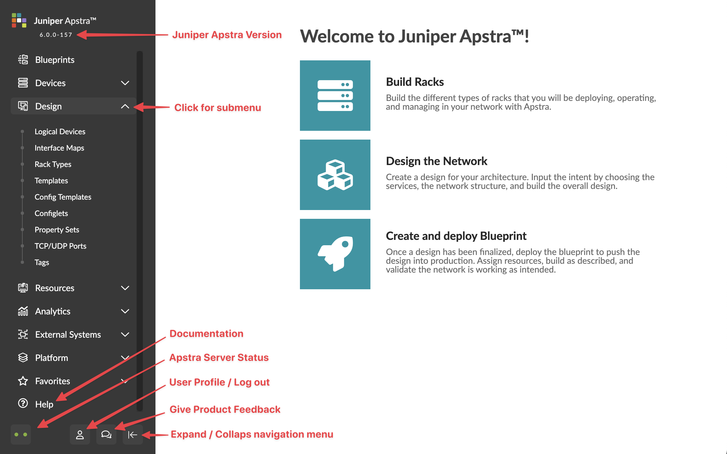
Access the GUI
-
From the log in page, enter the username and password. The username is
admin. The password is the secure password that you created when
configuring the server. The main GUI screen appears.
Design Your Network
The design process is highly intuitive because you base your design on physical building blocks such as ports, devices, and racks. When you create these building blocks and specify what ports are used, Apstra has all the information it needs to come up with a reference design for your fabric. Once your design elements, devices and resources are ready, you can start staging your network in a blueprint.
- Design Elements
- Install Device System Agents
- Create Resource Pools
- Build Your Network
- Deploy the Network
Design Elements
First, you design your fabric using generic building blocks that don't have site-specific details or site-specific hardware. The output becomes a template that you use later in the build stage to create blueprints for all your data center locations. You'll use different design elements to build your network in a blueprint. Keep reading to learn about these elements.
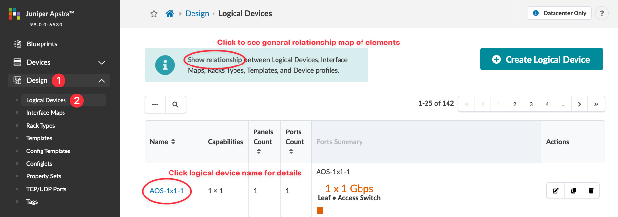
Logical Devices
Logical devices abstract physical devices, allowing you to map ports, speed, and roles without vendor-specific information. This helps you plan your network based on device capabilities alone before selecting hardware vendors and models. You can use logical devices in interface maps, rack types, and rack-based templates.
You have access to many predefined logical devices. You'll find them in the Design (global) catalog. From the left menu, navigate to Design > Logical Devices, then check the table for ones that meet your requirements.
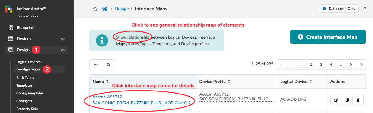
Interface Maps
Interface maps link logical devices to device profiles, which detail hardware model characteristics. Before checking the Design catalog for interface maps, know which models you'll use. You assign interface maps when you build your network in the blueprint.
You have access to many predefined logical devices. You'll find them in the Design (global) catalog. From the left menu, navigate to Design > Interface Maps, then check the table for ones that meet your requirements.
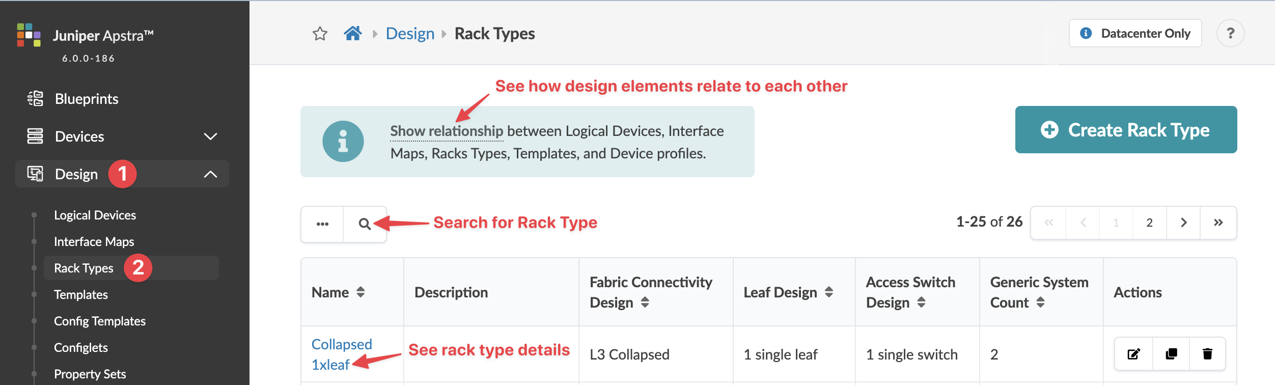
Rack Types
Rack types are logical representations of physical racks. They define the type and number of leafs, access switches and/or generic systems (unmanaged systems) in racks. Rack types don't specify vendors, so you can design your racks before selecting hardware.
You have access to many predefined rack types. You'll find them in the Design (global) catalog. From the left menu, navigate to Design > Rack Types, then check the table for ones that meet your requirements.
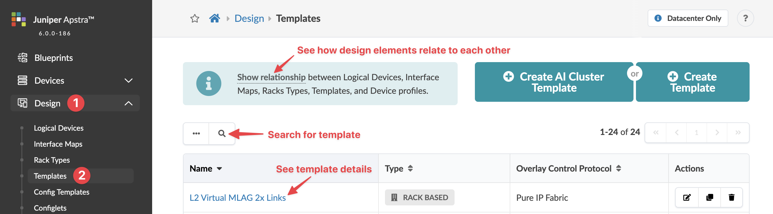
Templates
Templates specify a network's policy and structure. Policies can include ASN allocation schemes for spines, overlay control protocol, spine-to-leaf link underlay type and other details. The structure includes rack types, spine details and more.
You have access to many predefined templates. You'll find them in the Design (global) catalog. From the left menu, navigate to Design > Templates, then check the table for ones that meet your requirements.
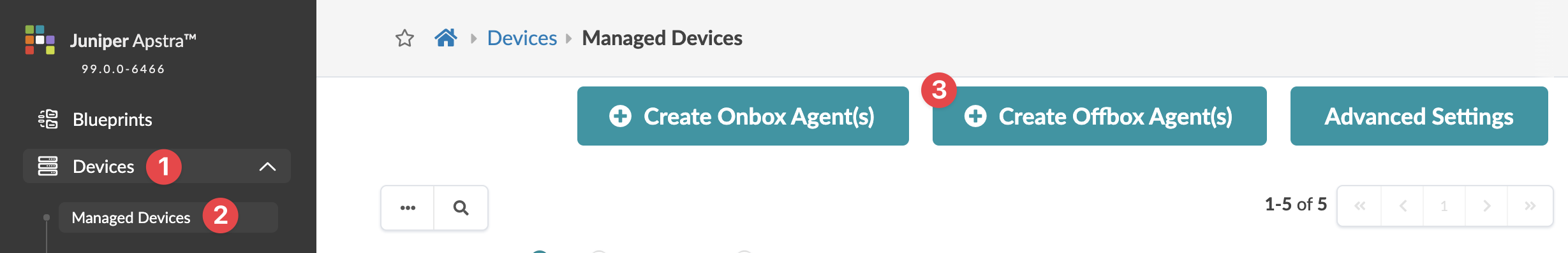
Install Device System Agents
-
From the left navigation menu in the GUI, navigate to Devices >
Managed Devices and click Create Offbox Agent(s).
-
Configure the OffBox System Agent(s) parameters:
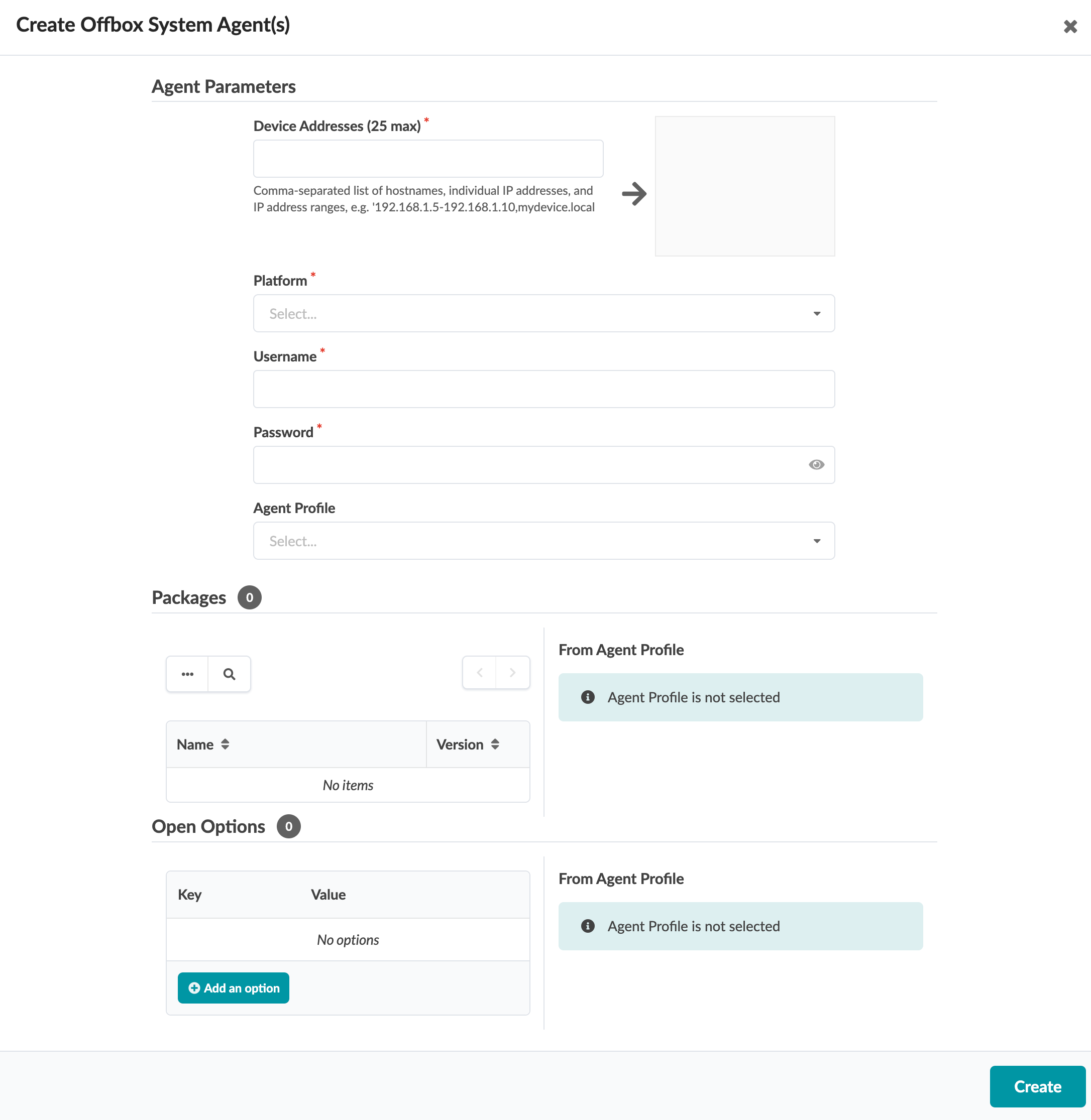
Enter the device management IP addresses.
Select Junos from the platform drop-down list.
Enter a username and password.
Click Create to create the agent and return to the managed devices summary view.
-
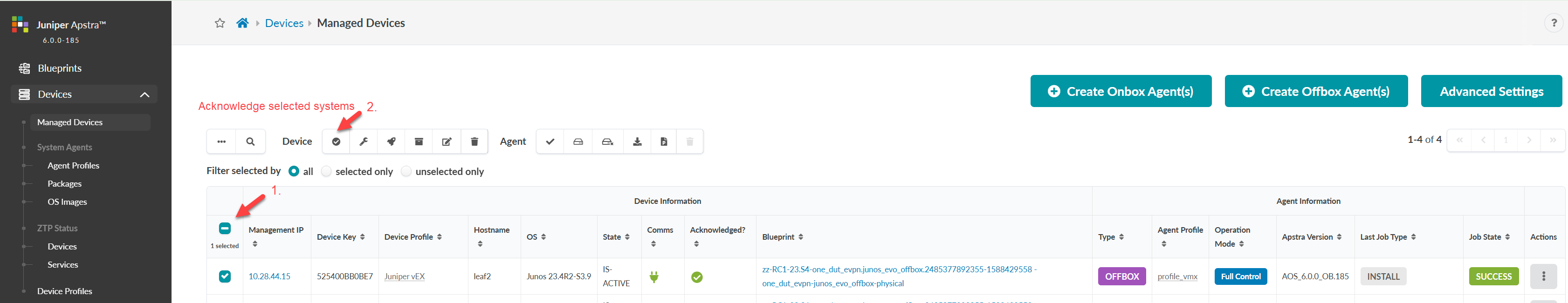
Select the check boxes for the devices, then click the
Acknowledge selected systems button (first
one on the left).
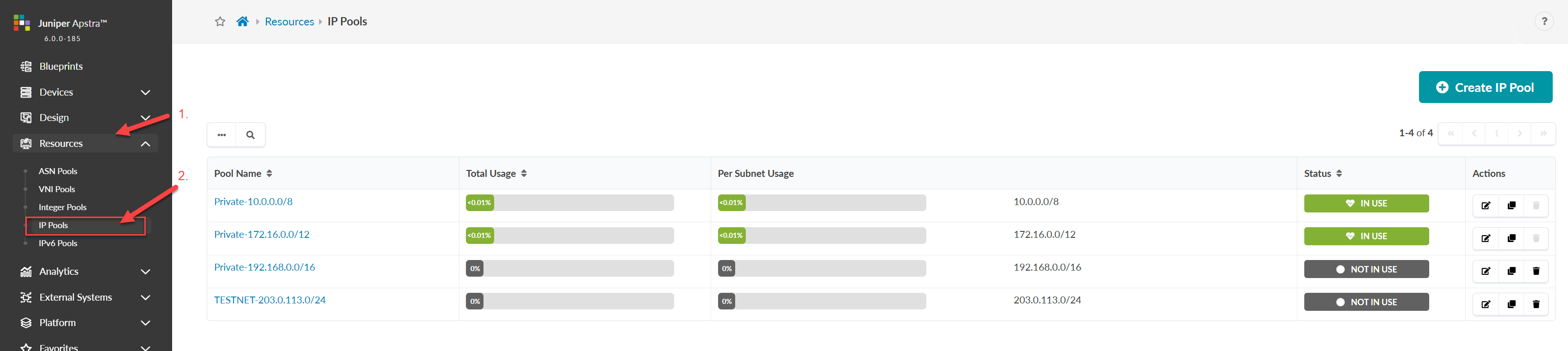
Create Resource Pools
-
From the left navigation menu, navigate to Resources > IP
Pools and click Create IP Pool.
Build Your Network
When you've got your design elements, devices and resources ready, you can start staging your network in a blueprint. Let's create one now.
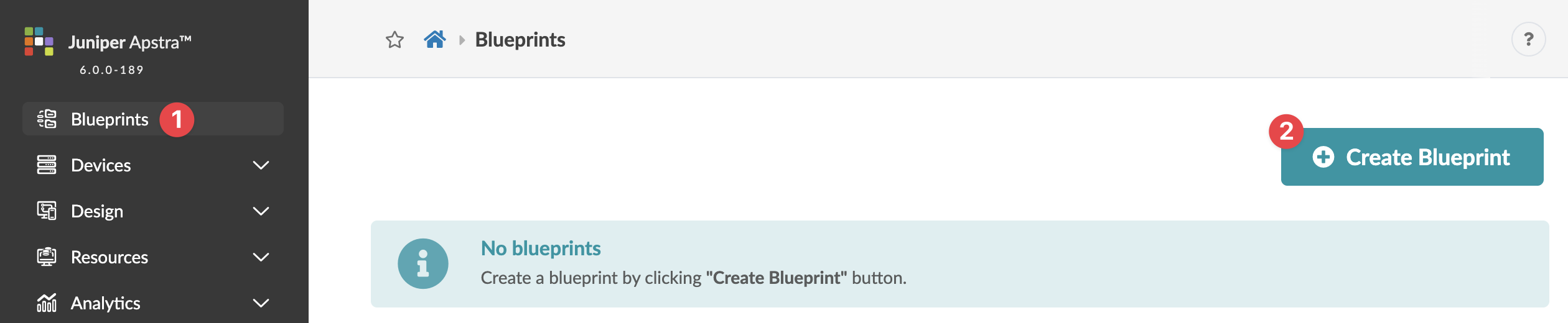
Create a Blueprint
-
From the left navigation menu, click
Blueprints, then click Create
Blueprint.
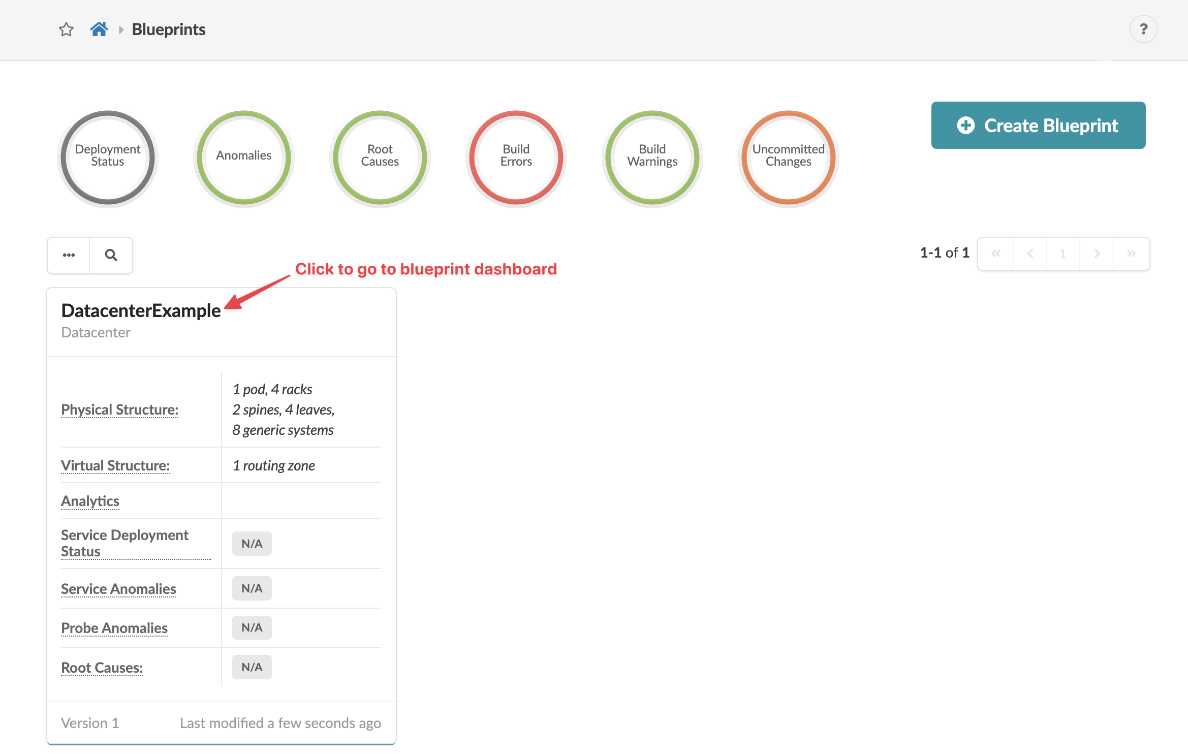
-
Click Create to create the blueprint and
return to the blueprint summary view. The summary view shows the
overall status and health of your network.
 When you meet all the requirements for building the network, the build errors are resolved and you can deploy the network. We'll start by assigning resources.
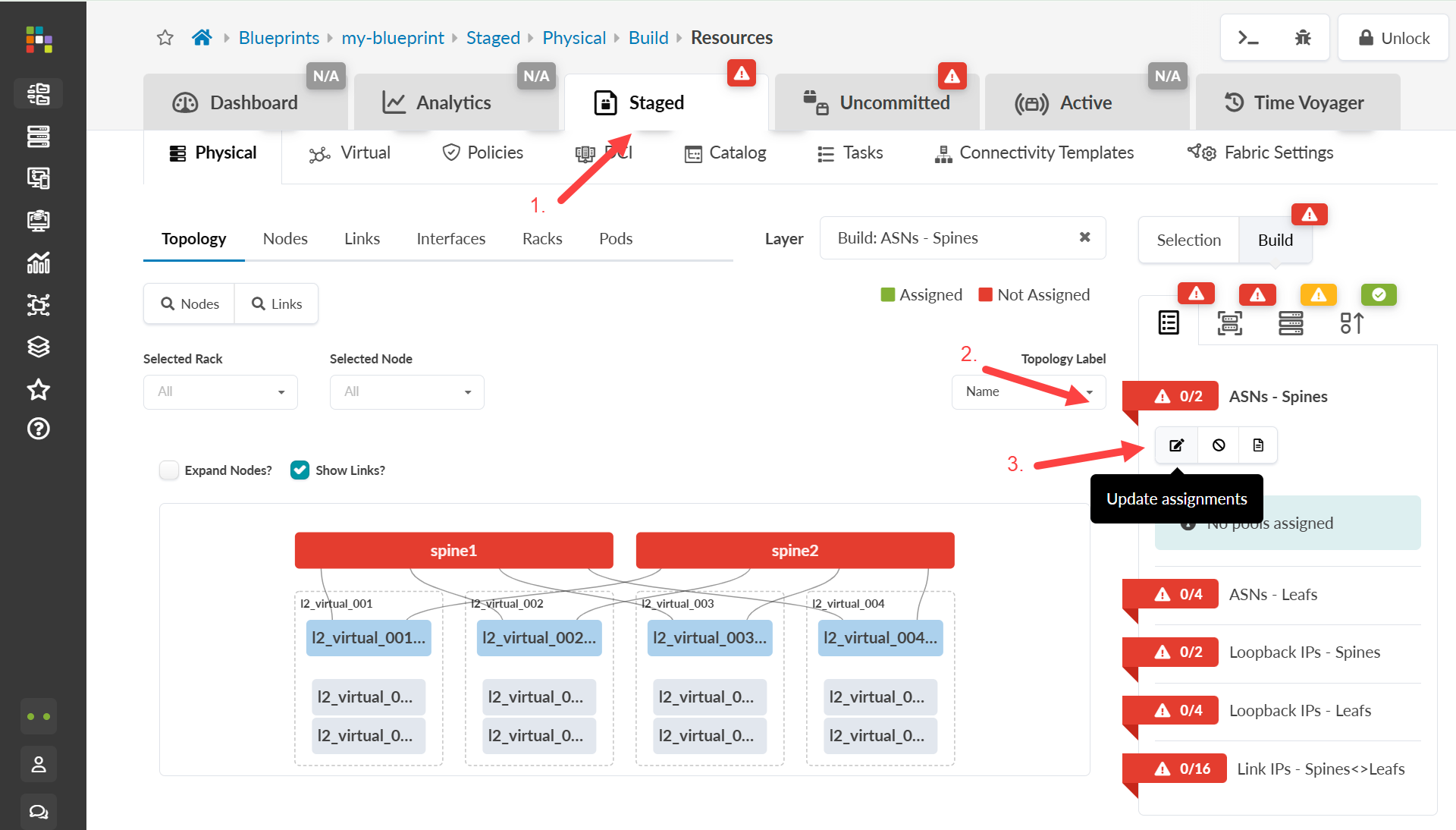
Assign Resources
-
Click one of the red status indicators, then click the
Update assignments button.
Assign Interface Maps
-
In the Build panel, click the
Device Profiles tab.
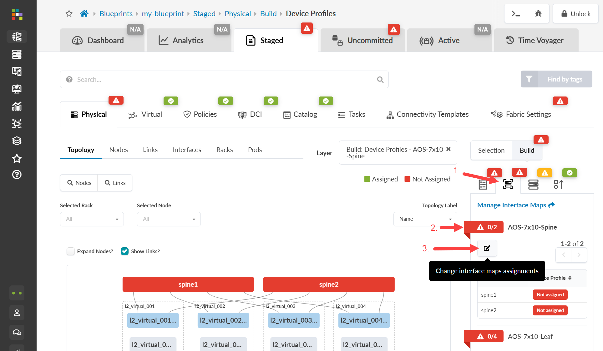
- Click a red status indicator, then click the Change interface maps assignments button (looks like an edit button).
- Select the appropriate interface map for each node from the drop-down list, then click Update Assignments. When the red status indicator turns green, the interface maps have been assigned.
- Continue assigning interface maps until all the required status indicators are green.
Assign Devices
-
In the Build panel, click the
Devicestab.
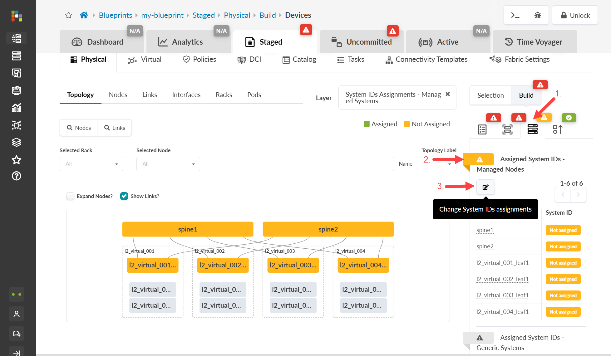
- Click the status indicator for Assigned System IDs (if the nodes list is not already displayed). Unassigned devices are indicated in yellow.
- Click the Change System IDs assignments button (below Assigned System IDs) and, for each node, select system IDs (serial numbers) from the drop-down list.
- Click Update Assignments. When the red status indicator turns green, system IDs have been assigned.
Cable Up Devices
-
Click Links (towards the left of the screen)
to go to the cabling map.
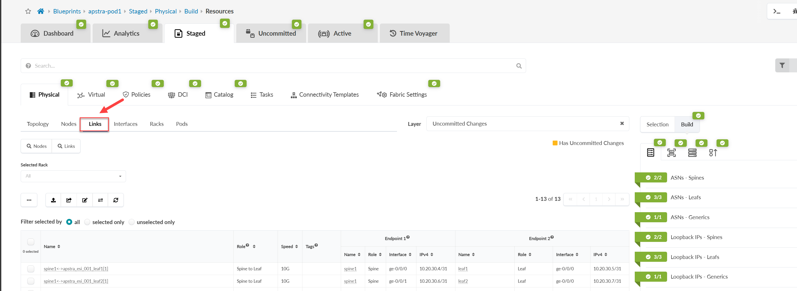
- Check the calculated cabling map and cable up the physical devices according to the map. If you have a set of pre-cabled switches, ensure that you have configured interface maps according to the actual cabling so that calculated cabling matches the actual cabling.
Deploy the Network
-
From the top navigation menu, click Uncommitted
to review staged changes. To see details of changes, click one of the
names in the table.
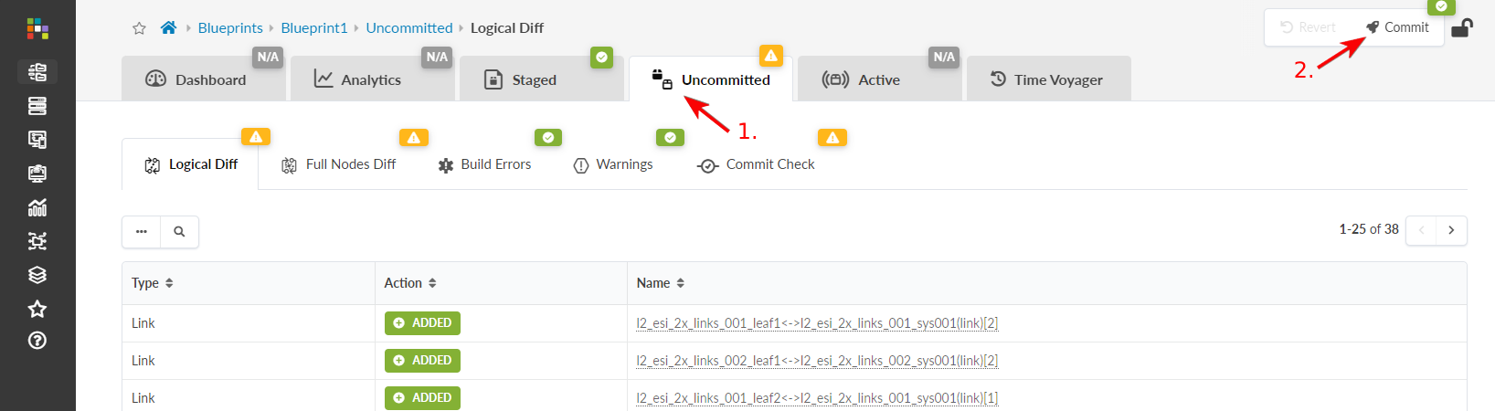
- Click Commit to go to the dialog box where you can add a description and commit changes.
- Add a description. When you need to roll back a blueprint to a previous revision, this description is the only information available regarding what has changed.
- Click Commit to push the staged changes to the active blueprint and create a revision.