Mixed Link Speeds between Leaf and Spine
The leaf devices in your racks can have different uplink speeds to a spine. When designing for mixed speeds, make sure you plan sufficient ports for spine-to-leaf connections with mixed link speeds for Day 0, and for adding racks as a Day 2 operation. The spine logical device must have mixed port speeds defined that specify the port role as Leaf for the required number of ports. The following limitations apply:
- Parallel links (leaf to spine) between the same devices cannot have mixed speeds.
The example below shows the process for creating rack types and templates with mixed link speeds between leafs and spine.
-
Create an L3 Clos rack type with leafs of differing uplink speeds to the
spine role. (See Rack
Types for details.)
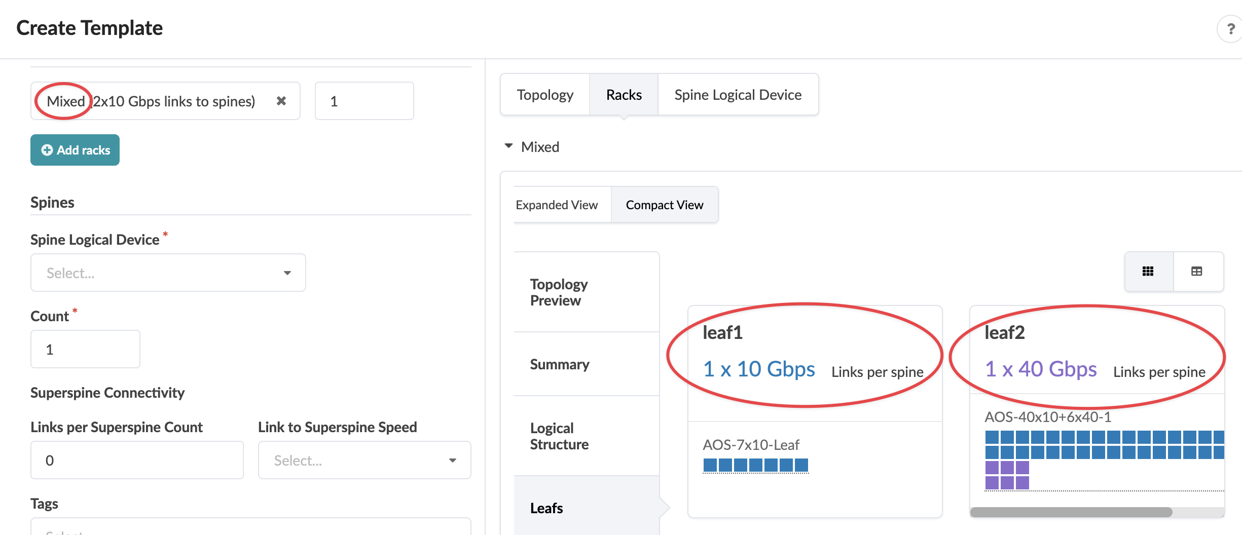
In our example, the first leaf uses the logical device AOS-7x10-Leaf (seven 10 Gbps ports) and the second leaf uses the logical device AOS-40x10+6x40-1 (forty 10 Gbps ports and six 40 Gbps ports).
-
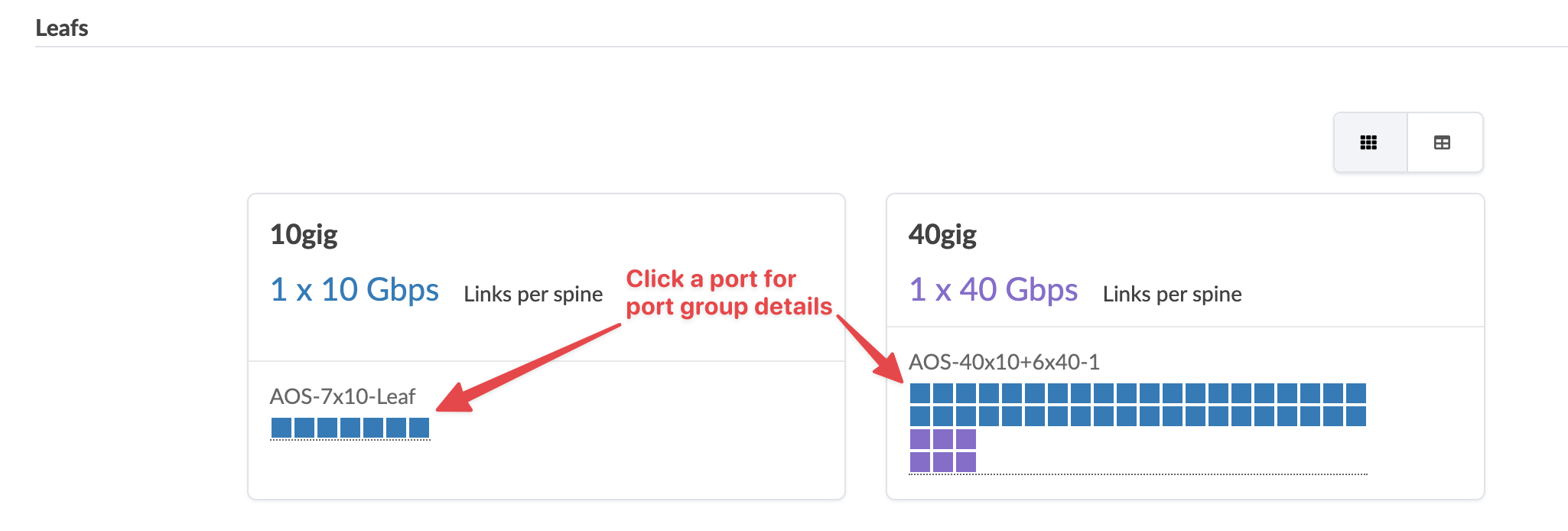
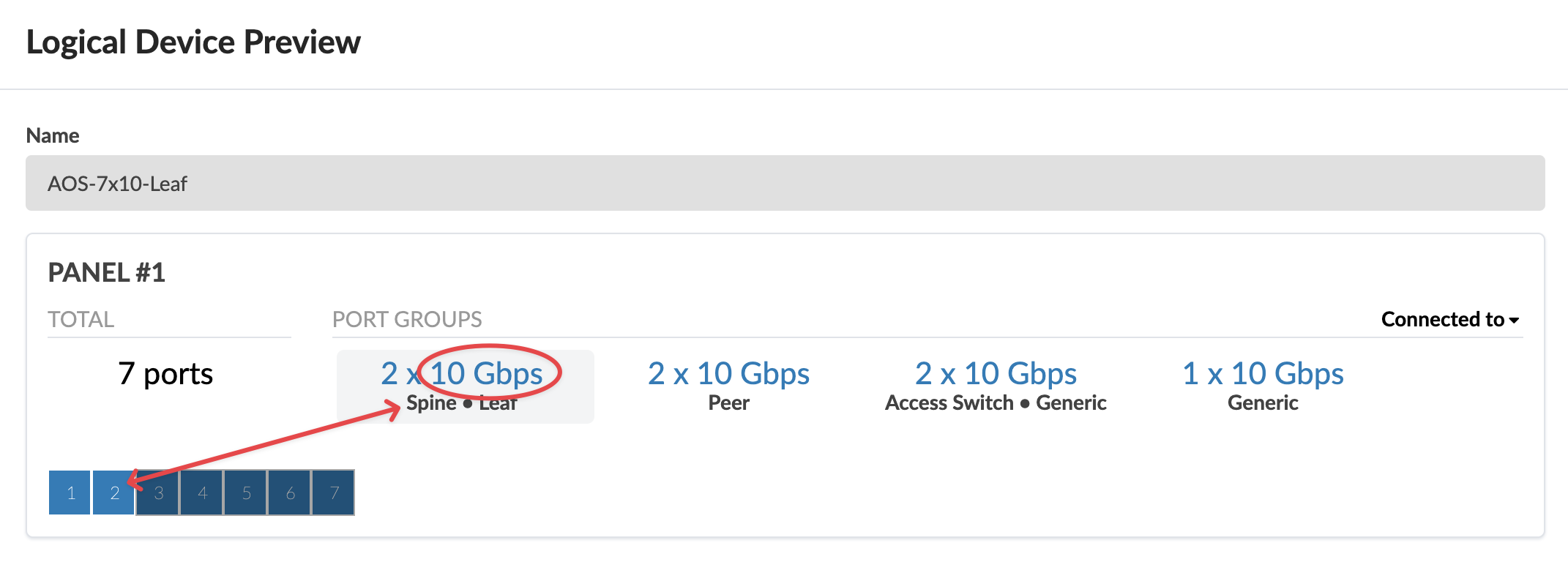
On the rack type details page you can click a port (as shown in the screen shot
above) to see roles assigned to each of the ports. You can see when clicking on
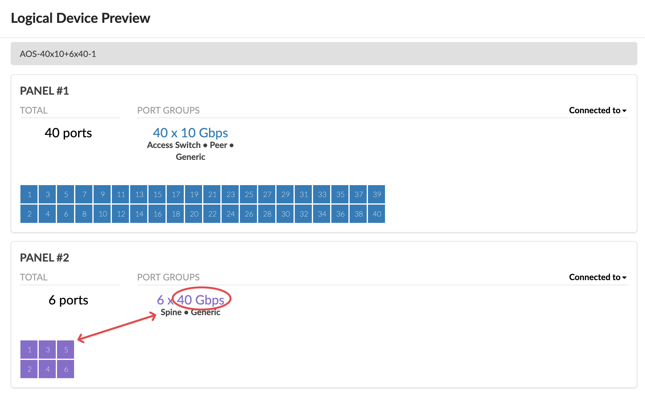
the 10gig leaf that 10 Gbps ports are assigned the spine role, and when clicking
the 40gig leaf, 40 Gbps ports are assigned the spine role.
-
Create a Rack Based template based on the mixed speed rack type. See
Templates for
details.