Create External Generic System
When you want to connect your Apstra-managed fabric to a system that's not managed in the Apstra environment, you use generic systems and external generic systems. These systems can be external routers, firewalls, or whatever else you want; you specify their roles with tags. If the system is part of a rack topology, we call it a generic system (or internal generic system). If the system is not part of a rack topology, we call it an external generic system.
-
From the blueprint, navigate to Staged > Physical >
Topology and select the leaf, spine or superspine to connect to the new
external generic system.
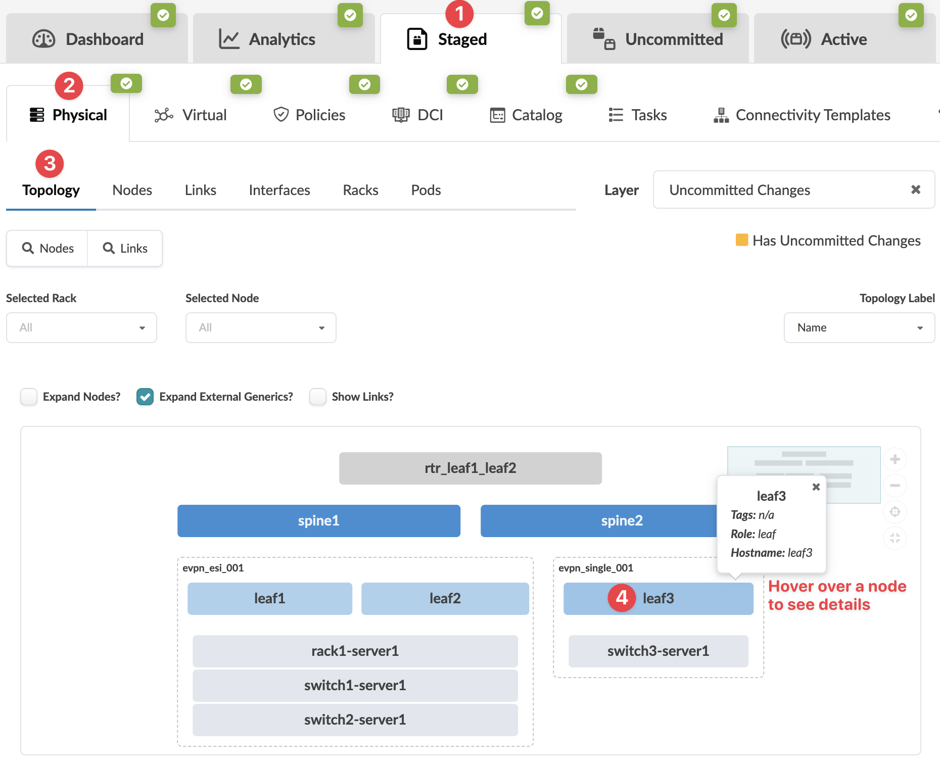 The Topology view of the selection appears.
 -
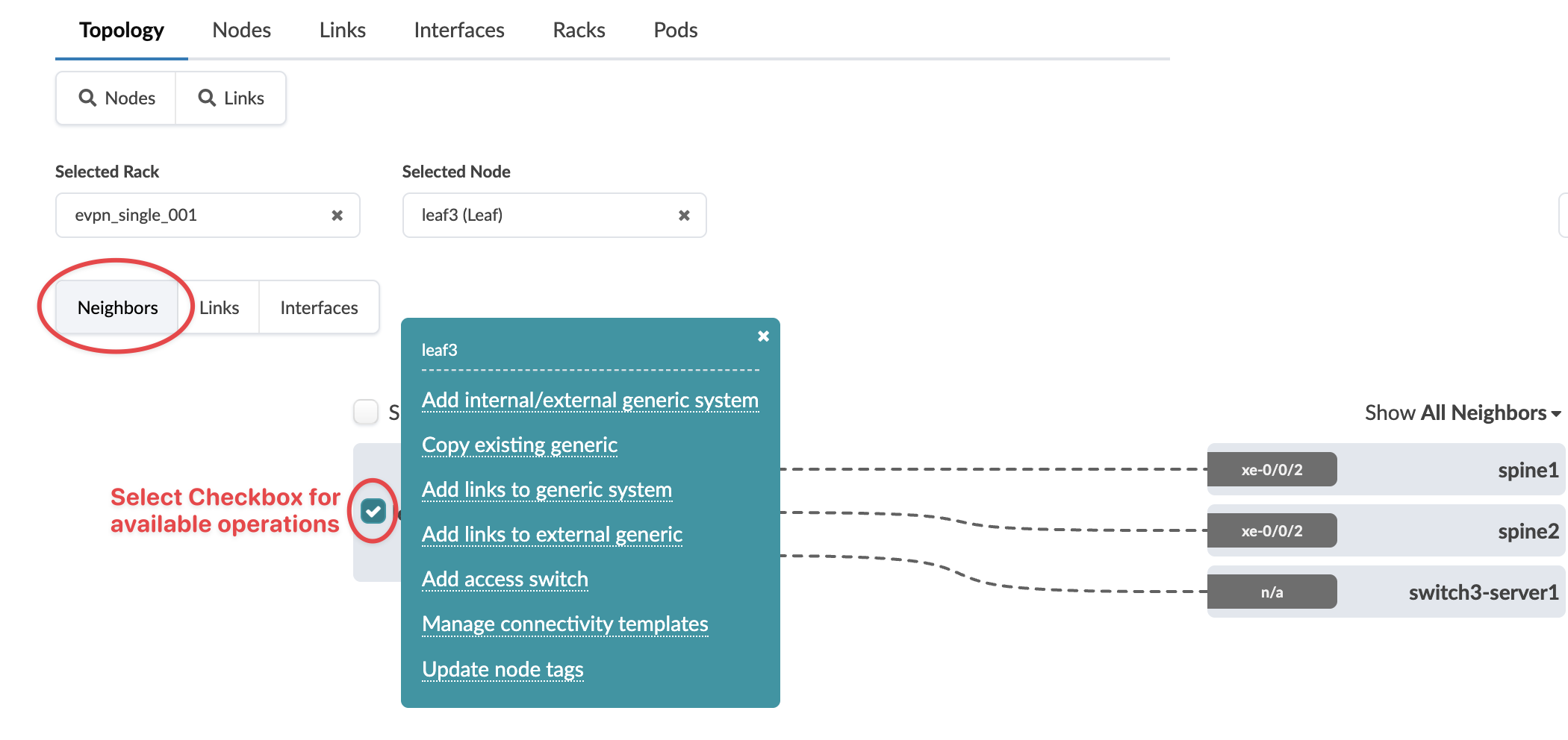
Select the node check box to see the operations available for that node (and that you
have permissions for), then click Add internal/external generic
system.
 Note:
Note:You can also get to the selection page from the Nodes view. From the blueprint, navigate to Staged > Physical > Nodes, click the node name in the table, then click the node name that appears at the top of the Selection panel (on the right side of the page).
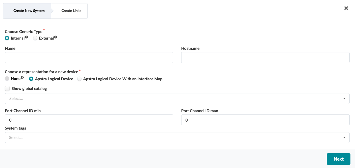
The Create New System dialog opens. -
For Generic Type, select External.
-
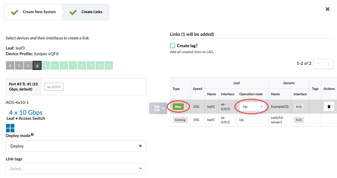
Select an available port and transformation. The gray Add Link
button turns green. Click Add Link.
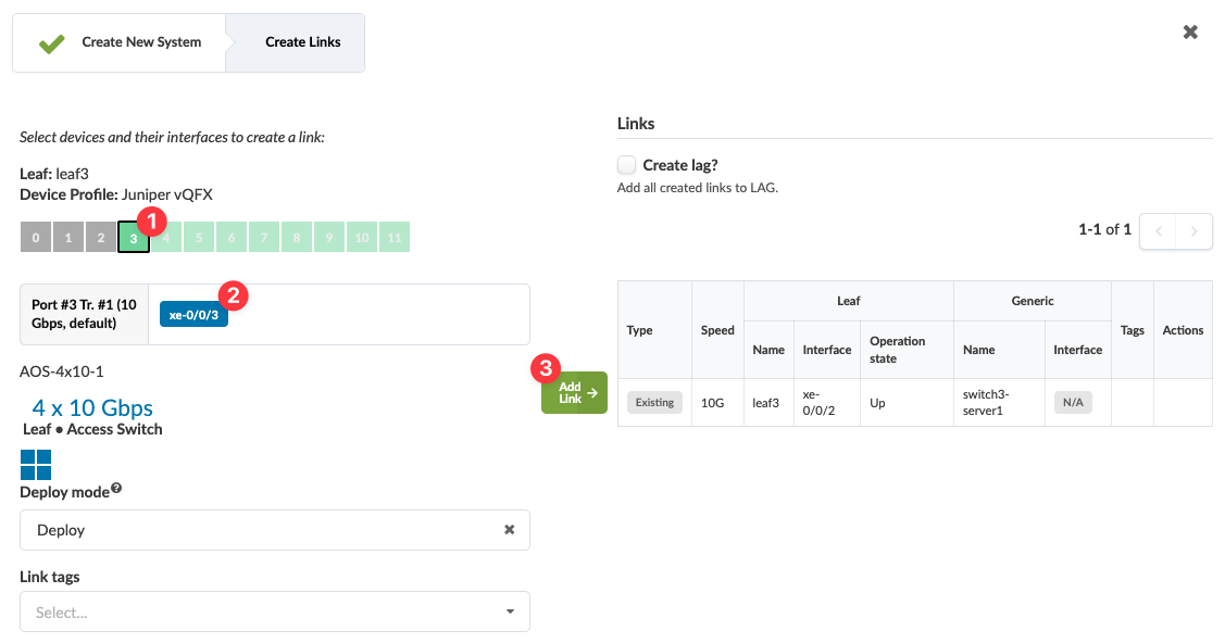 The link is added to the link table.
 -
The operation mode (new in Apstra version 5.0.0) for new links defaults to
Up. You have the option of setting it to
Down, from the drop-down list.
-
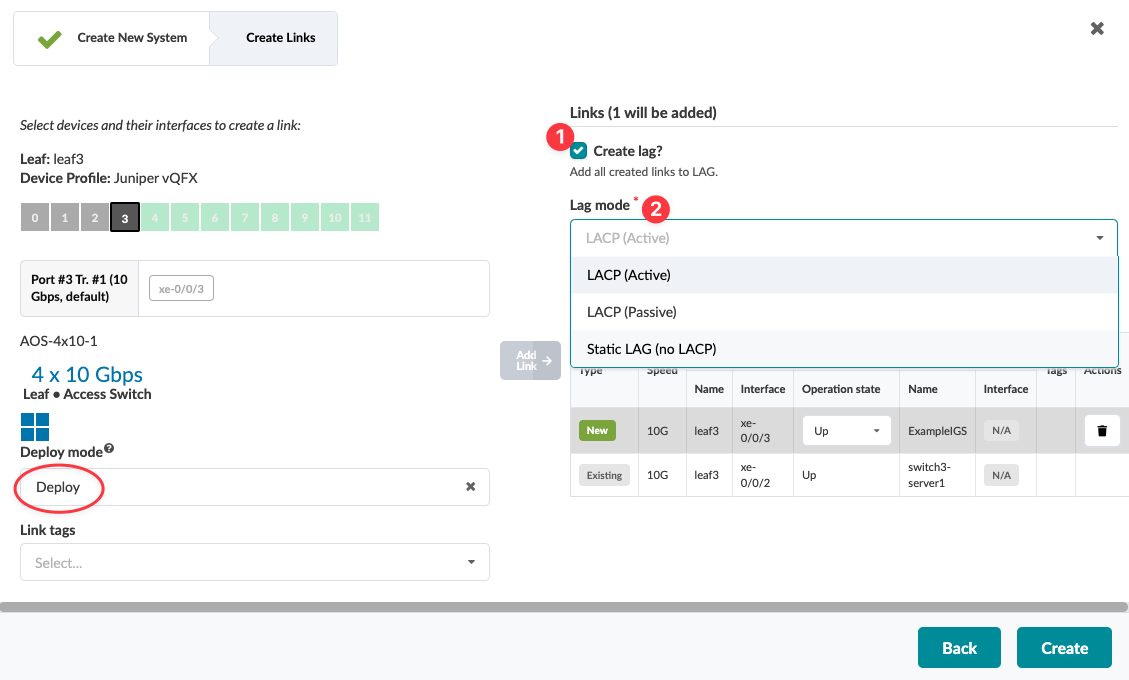
You have the option of creating a LAG when you create a generic system (new in Apstra
version 5.0.0). Click the Create lag check box, then select the LAG
mode from the drop-down list.
When you're ready to activate your changes, go to the Uncommitted tab to review and commit (or discard) your changes.