Help us improve your experience.

Let us know what you think.

Do you have time for a two-minute survey?


Creating a Custom Telemetry Collector

SUMMARY This topic describes the steps that are required to create a custom telemetry collector.

In this topic, we'll walk you through creating your own custom telemetry service using BFD as an example. In our example, the telemetry service collects the state of the BFD sessions you just configured. Our goal is to alert operations that a BFD session is down.

Execute the CLI Command

Starting in Apstra version 4.2.0, you can run CLI show commands for Junos devices directly from the Apstra GUI. Although you can run show commands without opening a CLI session, its primary purpose is to help you create your own custom telemetry collectors.

You can execute CLI commands from within the staged or active blueprint (shown in our example), or from the Devices > Managed Devices page.

To use the CLI command feature, navigate to a deployed Junos device in your blueprint as follows:

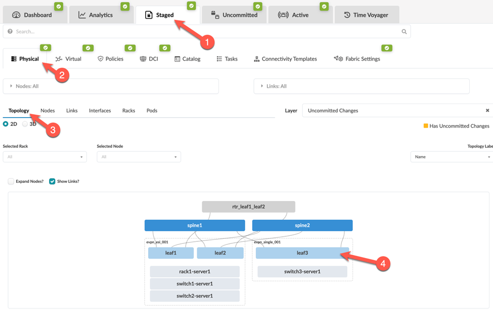
  1. From your blueprint, select Analytics > Staged Physical Topology (or Staged > Physical > Nodes) and then select your Juniper device node.
    Staged Changes in Network Management Interface showing a 2D Physical Topology with highlighted node leaf3 in a leaf-spine architecture.
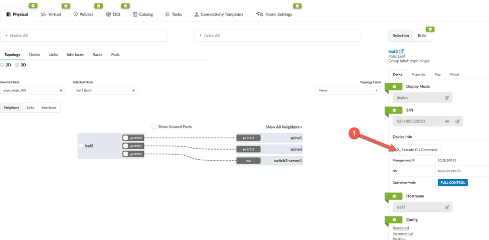
  2. In the Selection section that appears in the right panel, on the Device tab, click Execute CLI Command.
    Network management interface showing node leaf3 connected to spine1 and spine2. Right panel details leaf3's serial number, management IP, OS, and operation mode.
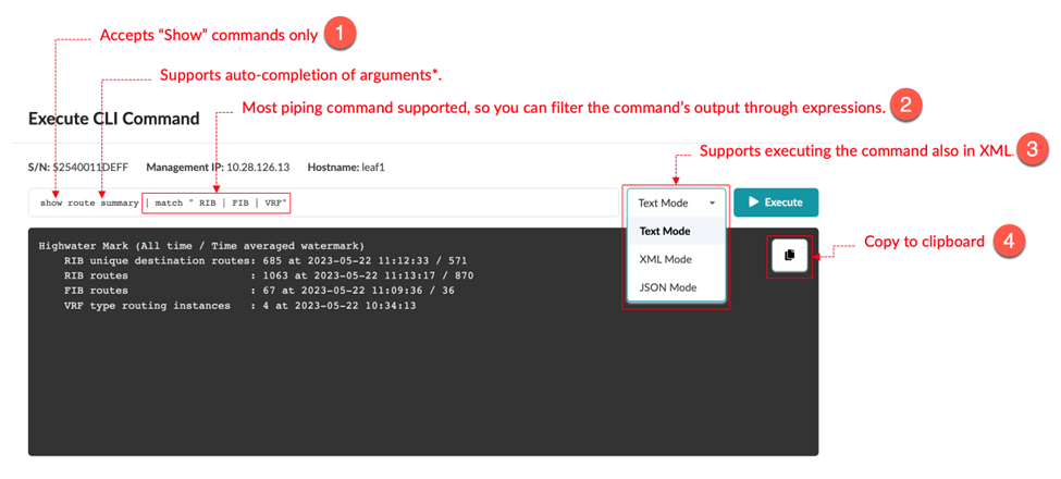
    In the dialog box that opens, select how you want to view the results: Text Mode, XML Mode, or JSON mode. Here we show examples of Text Mode and XML Mode.
    CLI interface for executing show commands on a network device. Features auto-completion, piping, XML/JSON modes, and clipboard copy.
    Note:

    The CLI supports only Junos show commands. You cannot run commands that affect the device state, such as request system reboot. For information about the various show commands, see the CLI User Guide for Junos OS.

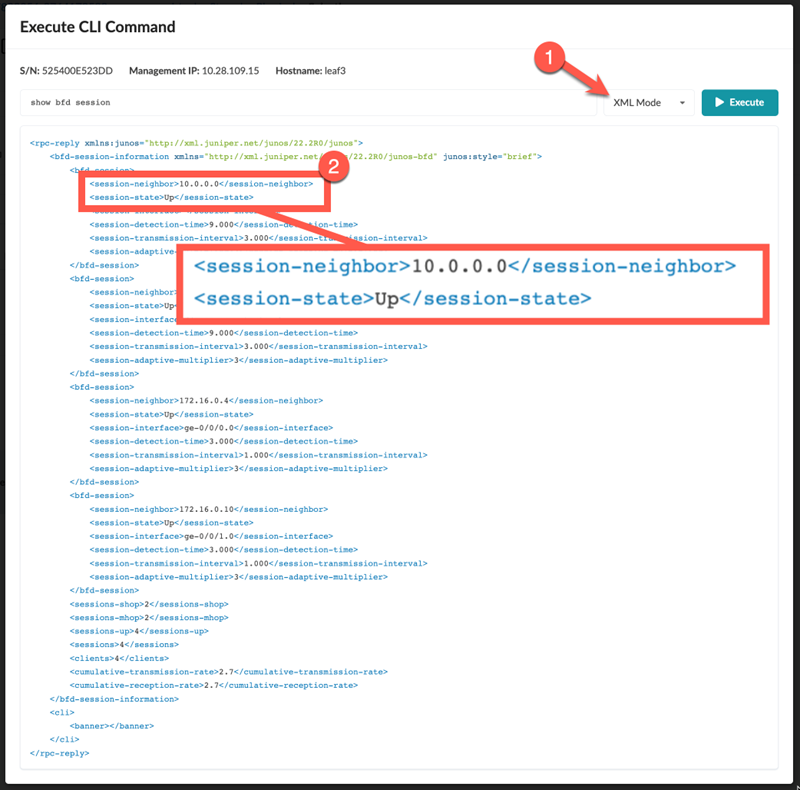
    Now, run the same show command (show route summary), but choose XML Mode.

    CLI output of `show bfd session` on a Juniper device, in XML format, showing BFD session neighbor 10.0.0.0 and session state Up.
    In the XML output, the XML path (BDF session) information is highlighted. This session information is what we'll use to create our telemetry collection service.

Identify the Key and Value of Interest from the CLI Output

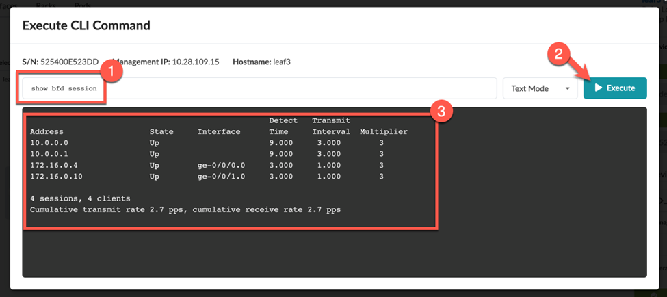
This example shows you how to use the Execute CLI Command to view the neighbor addresses and state information (Up or Down) for your BDF session.
  1. Enter the show command (in this example, show bfd session).
  2. Click Execute to view the CLI output.
    CLI window with command show bfd session executed displaying BFD session details: address, state up, interface, detect time, transmit interval, multiplier, and session summary.

Create a Service Schema

To create your custom service collector, you first need to create a service schema to define how you want the returned data to be structured and stored.
Note:

A single telemetry service schema can have multiple collectors associated with it.

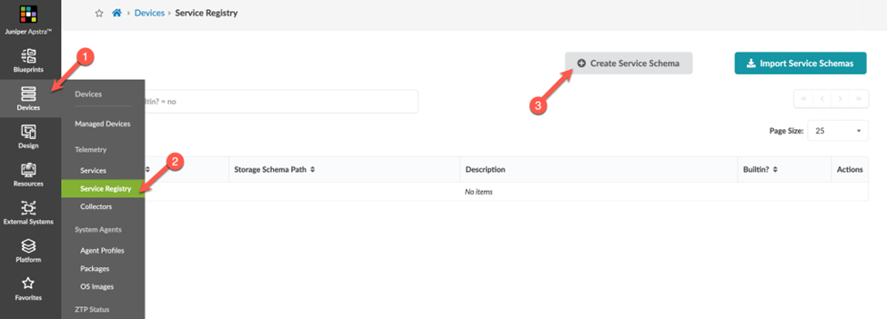
  1. From the left navigation menu, navigate to Devices > Service Registry and click the Create Service Schema button.
    Juniper Apstra interface showing Service Registry section with Create Service Schema button and empty table for service schemas.
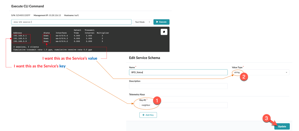
  2. In the dialog box that opens, define your schema. This step identifies how the collector output is to be structured.
    Configuration interface for a network management system with CLI command section displaying BFD session details and Edit Service Schema section. User highlights IP addresses 192.168.0.1, 192.168.0.3, 192.168.0.9 as Service's value. Service named BFD_Status created with telemetry key neighbor and value type string. Annotations guide mapping CLI output to service schema configuration.
  3. Map the Telemetry Keys and Value Type.
    The telemetry key and value type is collection of key-value pairs that gets posted to Apstra.
    • The telemetry key is a string that identifies the interface name.

    • The value type is the piece of data that the probe executes against. The value type is usually a string (text), but could also be an integer (whole number).

    In our example, we defined the Service's key as neighbor and the Value Type as string.
  4. Click Update.
Now, let's proceed to the final step, Create a Collector.

Create a Collector

We've defined the data to collect and how we want this data to be organized and structured. Now we'll map these parts together.
Note:

A single telemetry service schema can have multiple collectors associated with it.

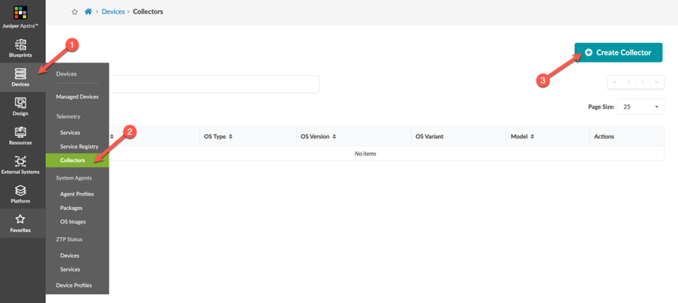
  1. From the left navigation pane, navigate to Devices > Collectors > Create Collector.
    Juniper Apstra UI showing Collectors section under Devices menu with steps to create a new collector. No collectors listed yet.
  2. Select the existing service schema (BFD) you created in the previous step and click Next.
    User interface for creating telemetry collector with tabs: Service, Platform, Command, Mapping. BFD selected in Service tab. Next button highlighted.
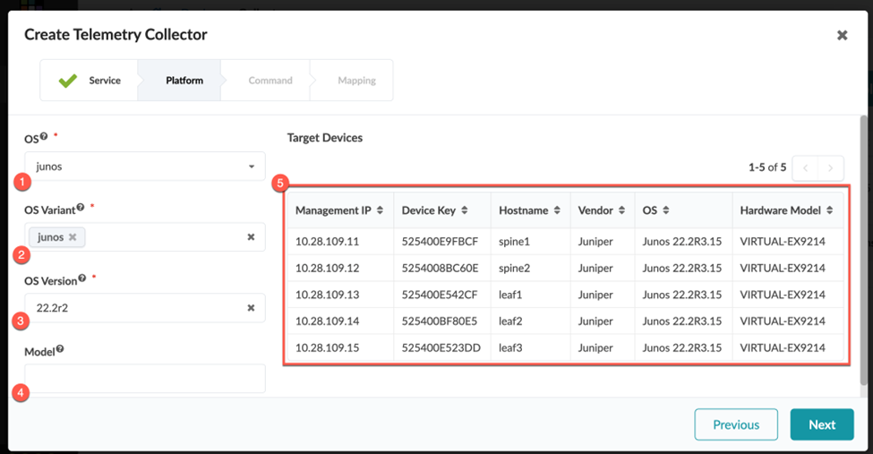
  3. Select the platform (OS, OS Variant, OS version, and Model) and devices to target for telemetry collection. Defining a mix of these inputs enables you to be very broad or very granular. For example, you might have a use case where you only want to apply telemetry on the border leaf devices.
    User interface for telemetry collector creation with fields: OS junos, OS Variant junos, OS Version 22.2r2, empty Model. Target Devices Table lists Juniper devices with Management IP, Device Key, Hostname, Vendor, OS Junos 22.2R3.15, Hardware Model VIRTUAL-EX9214. Navigation buttons Previous and Next at the bottom.
    1. Select the OS type , either junos or junos-evo.
      For more information on Junos-evo (also known as Junos OS Evolved) see the Junos OS Evolved documentation.
      Note:

      If you do not define a Junos-evo collector for Junos-evo devices, the collector uses the corresponding Junos definition. This means if you use the same command between Junos and Junos-evo, you can create a single Junos collector definition for that service. If the command exists only on Junos-evo, you create a single collector definition for Junos-evo.

    2. Select the OS Variant the device belongs to and determine the CLI schema for a given device.
    3. Select the minimum OS Version the device must run for the collector to execute. If multiple collector definitions with different OS versions exist for the same service, the collector automatically chooses the one closest to the version the device is running.
    4. (Optional) Specify a Model or a regular expression to filter based on a device model or series.
      The table shows a list of target devices currently managed in Apstra and matches the applied combination of filters.
    5. Click Next.
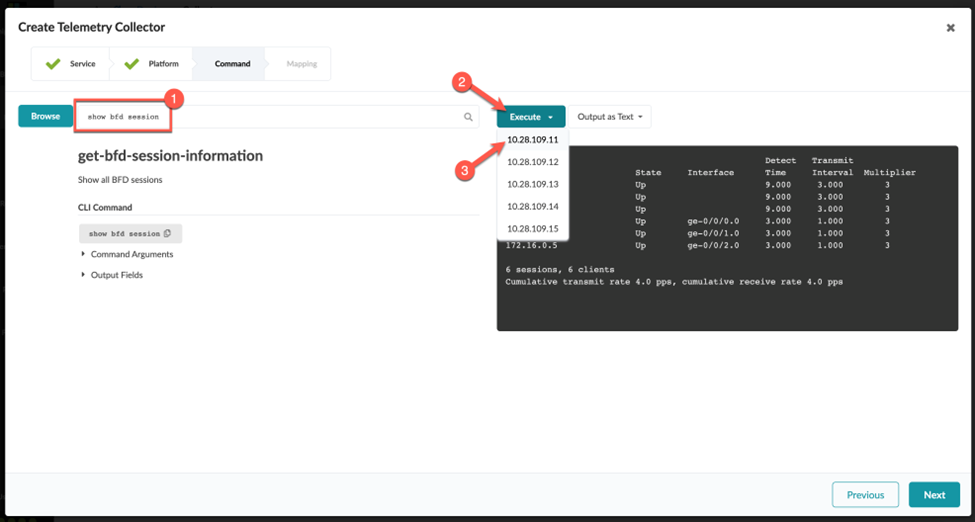
  4. Run the CLI command.
    Use the show command to gather the date you want to collect from the device (in this example, show bdf session ).
    User interface for creating telemetry collector, focused on executing 'show bfd session' command. Displays BFD session details and navigation tabs for setup workflow.
  5. Map the Keys and Value.
    So far, we've defined the service schema, the target platforms, and the command the custom telemetry collector will execute. Next, we'll map the key(s) you defined in your schema and the value you want to track.

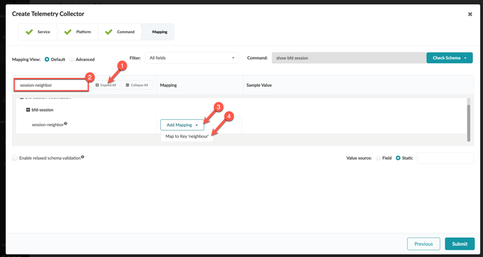
    To map the keys:

    1. Click Expand All to search for the RPC value you want to map.
      In the previous step, we established session-neighbor as the key value.
      User interface for telemetry collector creation, focused on Mapping step. Mapping view options: Default or Advanced. Filter set to All fields. Command: show bfd session. Mapping session-neighbor to Key neighbor. Relaxed schema validation option available. Submit button for configuration completion.
    2. Click Add Mapping.
    3. Assign session-neighbor to the key (in this example, neighbor).
      We defined this value earlier when we created a service schema.
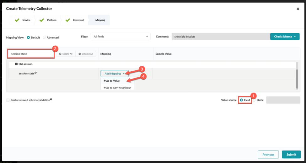
    To map the value:
    1. Select the Value Source. In our example, we want to populate the value based on the dynamic session-state field returned by this CLI command.
      Telemetry collector interface for mapping fields. Current step is Mapping. Mapping session-state under bfd-session to value or key neighbour. Options for default or advanced view, field filtering, adding mappings. Relaxed schema validation checkbox. Submit and back buttons available. Progress indicator shows steps Service, Platform, Command, Mapping.
    2. Search for the session-state field.
    3. Click Add Mapping.
    4. Assign session-state to map the value.
    5. Click Submit.

Validate That the Collector Is Working
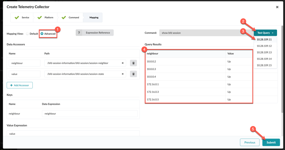
Finally, in Advanced view, validate that the collector is working. Verify that the query and test results match your expected results.

Telemetry collector interface with advanced mapping view selected. User entered command show bfd session. Test Query button present. Query results show BFD session neighbors and states. Submit button to save configuration. Data accessors and customization options available.

Congratulations! You successfully created a collector.

Note:

When you define the integer (number) values for a collector, you might need to enter a value expression for the collector to function. This is because Junos occasionally reports number data as a string. Before the collector can be processed, you must perform a conversion from string to integer on the Apstra side.
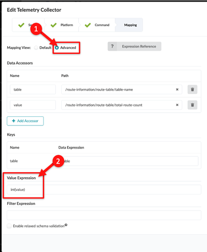
To define the integer (number) values for a collector, enter int(value) into the Value Expression field and click Submit.

Screenshot of telemetry collector configuration interface with Advanced mapping view. Data accessors table and value are defined with respective paths. Table key is mapped to table data expression. Value key has Value Expression int(value). Checkbox for enabling relaxed schema validation is present.