Interface Maps (Datacenter Design)
Example: Create Interface Map with Breakout Ports
To create dense server connectivity, let's create an interface map that breaks out the twenty-four 40 GbE transformable ports of an Arista DCS-7050QX-32 physical device to ninety-six 10 GbE ports of a 96x10-8x40-2 logical device.
96x10-8x40-2 is not one of the predefined logical devices that ships with Apstra software, so if you have not created it you won't find it in the drop-down list. If you'd like to follow along with this example, you can create the logical device before continuing.
- From the left navigation menu, navigate to Design > Interface Maps and click Create Interface Map. Leave the name blank. It will populate automatically as you enter more information.
- From the Logical Device drop-down list, select 96x10-8x40-2. This logical device has 96-10 GbE ports for servers and 8-40 GbE ports for uplinks to spine switches or external routers.
- From the Device Profile drop-down list, select Arista DCS-7050QX-32. This device has 24-40 GbE QSFP+ ports that are transformable (4x10 GbE or 1x40 GbE) and 8-40 GbE QSFP+ ports that are not transformable. As soon as both the logical device and device profile are selected, the interface map name is automatically populated.
-
Under Device profile interfaces (middle-right) click
Select Interfaces
for the 10 GbE
logical ports. This displays the port layout.
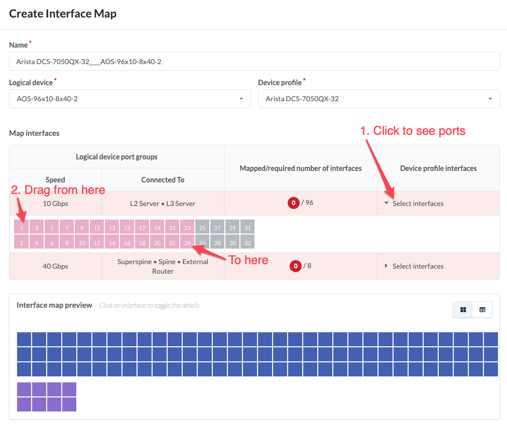
- Drag to select the first 24 ports. As the ports are selected the white numbers turn gray. When all interfaces are selected the red circle turns green.
-
Under Device profile interfaces (middle-right) click
Select Interfaces for the 40 GbE ports. This
displays the port layout.
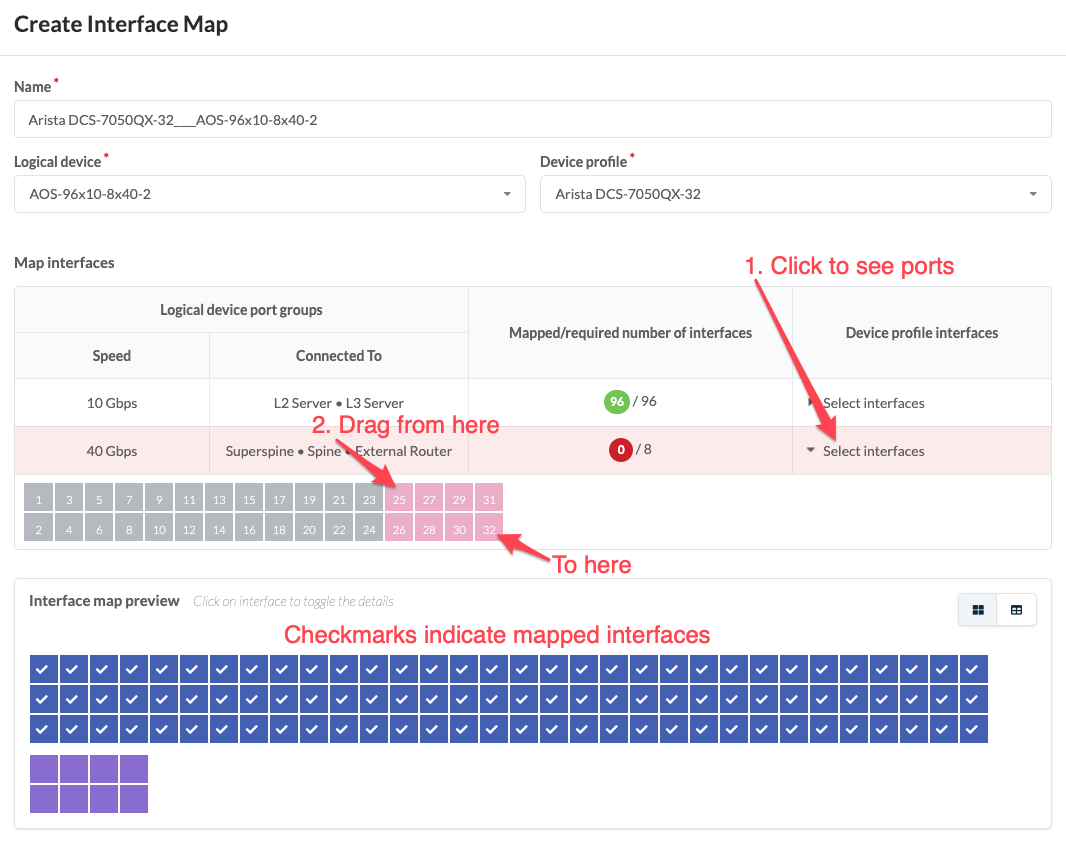
-
Drag to select the remaining 8 ports. As the ports are selected the white
numbers turn gray. When all interfaces are selected the red circle turns
green.
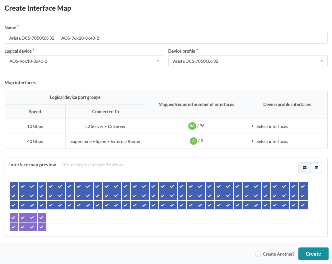
- Click Create to create the interface map and return to the table view. The new interface map is shown in the overview screenshot above.
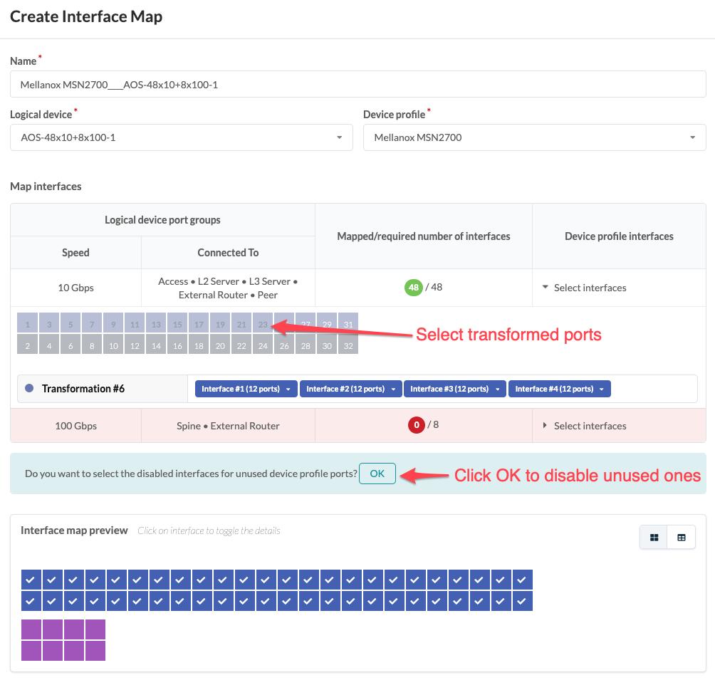
Example: Inter Port Constraints - Disabled Ports
Inter Port Constraint Overview
(Cumulus is no longer supported as of Apstra version 4.1.0, although Cumulus examples remain for illustrative purposes.) Inter port constraints for Cumulus devices are handled in both the device profile and the interface map. For Apstra to generate the correct ports.conf file with these constraints, the unused interfaces must be disabled in the interface map.
For example, if each of the top (odd-numbered) QSFP28 ports in a Mellanox
2700 device are split into four SFP28 ports, the bottom (even-numbered)
QSFP28 ports are blocked. (Source: https://docs.mellanox.com/display/sn2000pub/Cable+Installation) The
blocked interfaces must be disabled. 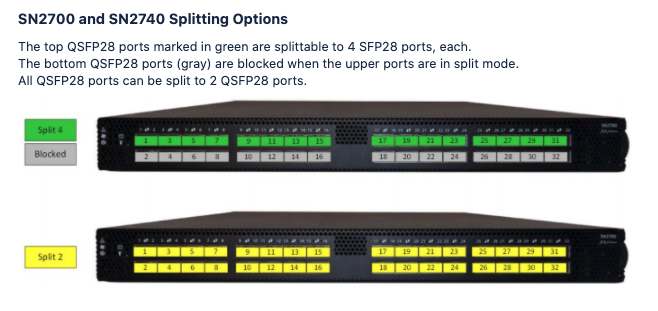 Using the predefined interface map
Mellanox_MSN2700_Cumulus__AOS-48x10_8x100-1 as an example, ports
1,3,5,7,9,11,13,15,17,19,21, and 23 were used to generate the 4x10G interfaces,
and the 5th transformation for ports 2,4,6,8,10,12,14,16,18,20,22, and 24 have
been disabled.
Using the predefined interface map
Mellanox_MSN2700_Cumulus__AOS-48x10_8x100-1 as an example, ports
1,3,5,7,9,11,13,15,17,19,21, and 23 were used to generate the 4x10G interfaces,
and the 5th transformation for ports 2,4,6,8,10,12,14,16,18,20,22, and 24 have
been disabled. 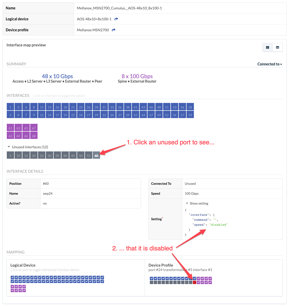
Disable Unused Ports
When creating an interface map that requires disabling ports for inter port
constraints, the prompt Do you want to select the disabled interfaces for
unused device profile ports? is displayed. To disable the corresponding
ports, click OK.