Create External Generic System
When you want to connect your Apstra-managed fabric to a system that's not managed in the Apstra environment, you use generic systems and external generic systems. These systems can be external routers, firewalls, or whatever else you want; you specify their roles with tags. If the system is part of a rack topology, we call it a generic system. If the system is not part of a rack topology, we call it an external generic system. This page shows you a couple of ways to add external generic systems.
Create External Generic System (from Topology View)
-
From the blueprint, navigate to Staged > Physical >
Topology and select the spine or leaf to connect to the new
external generic system.
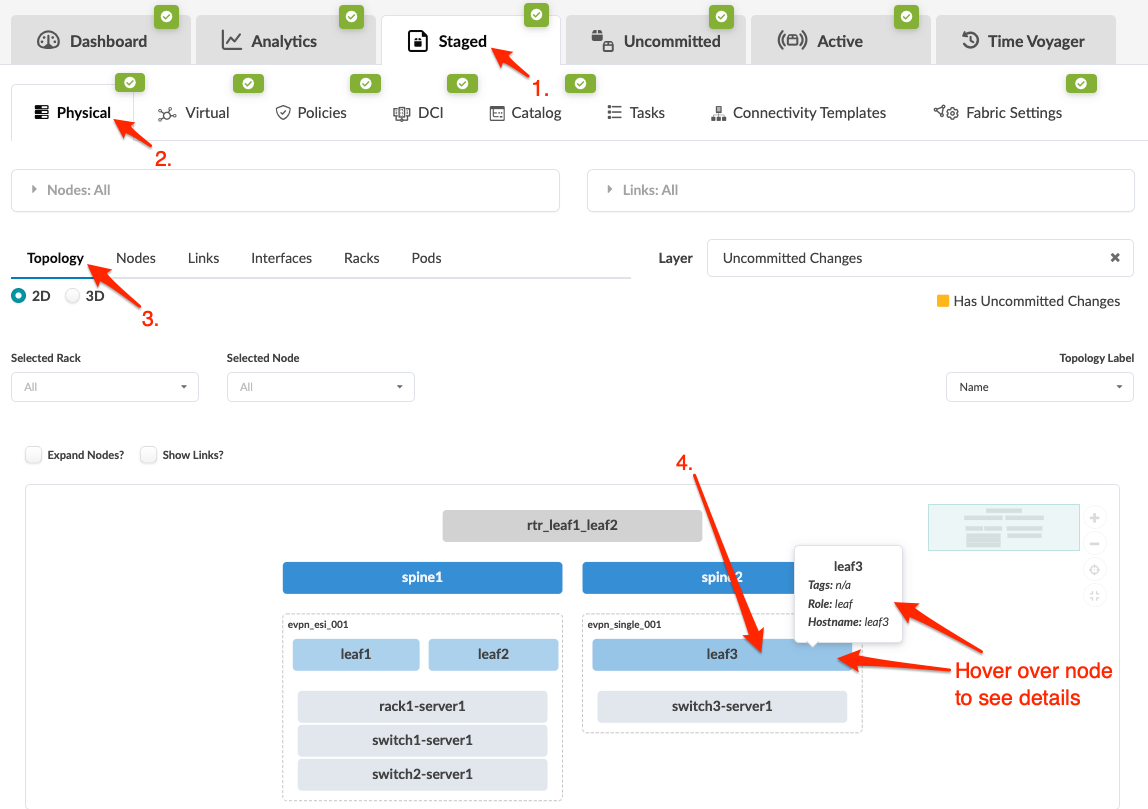
-
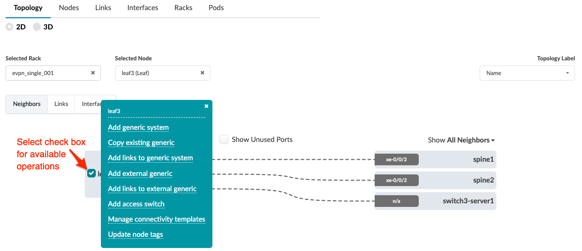
Select the node check box to see the operations available for that node
(and that you have permissions for). (Image below is for Apstra version
4.2.0.)
 Note:
Note:You can also get to the selection page from the Nodes view. From the blueprint, navigate to Staged > Physical > Nodes, click the node name in the table, then click the node name that appears at the top of the Selection panel (on the right side of the page).
-
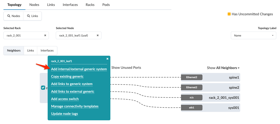
If you're using Apstra version 4.2.0, click Add external
generic. If you're using Apstra version 4.2.1, click
Add internal/external generic system as shown in
the 4.2.1 screenshot below.
-
Enter a unique label and (optional) hostname.
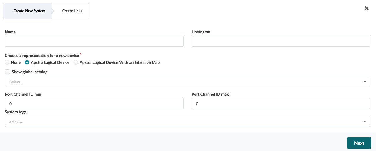
-
Enter tags (optional) to identify the role(s) of the new external generic
system, then click Next. The Create
Links dialog opens.
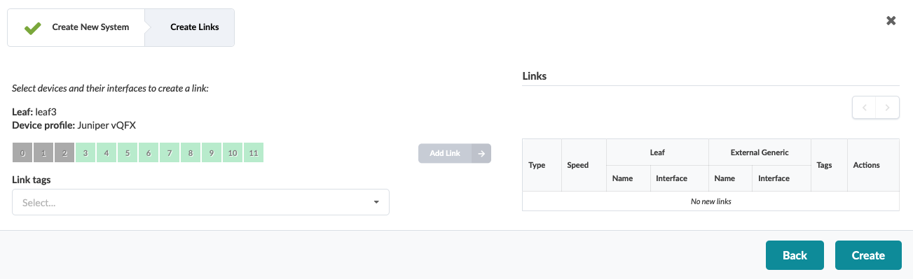
-
Select an available port and transformation, then click the Add
Link button that turns from gray to green.
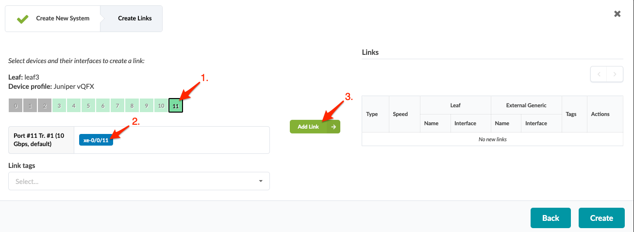
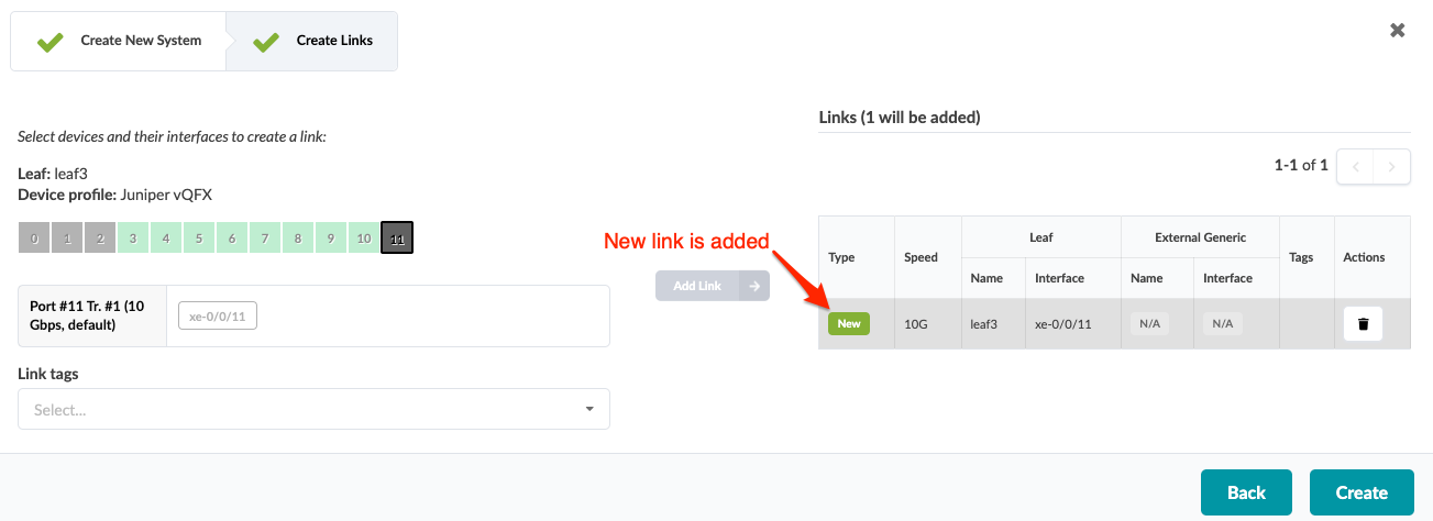
-
Click Add Link. The link is added to the link
table.
When you're ready to activate your changes, commit them from the Uncommitted tab.
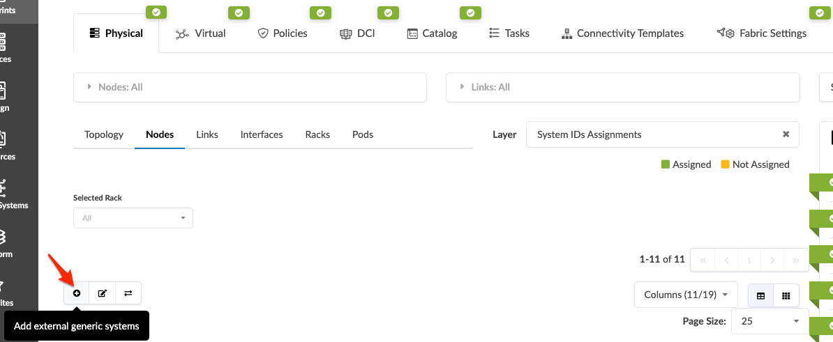
Create External Generic System (from Nodes View) (4.2.0 only)
-
From the blueprint, navigate to Staged > Physical >
Nodes and click the Add external generic
systems button to open its dialog.
You've created an external generic system that's not yet linked. You can either select the node (leaf, spine) first then link to the external generic system, or you can select the external generic system first, then link to a node. See below for links to the procedures.