Step 1: Begin
In this guide, we provide a simple, three-step path, to quickly get the Juniper Networks® SSR100 Series devices (SSR120 and SSR130), SSR400 Series (SSR400, SSR400-C, SSR440, SSR440-2AC, SSR440-C, and SSR440-C-2AC), and SSR1000 Series devices (SSR1200, SSR1300, SSR1400, and SSR1500) up and running on Juniper Mist™ cloud. You can on-board a single SSR device using your mobile phone, or one or more devices using your computer. Once on-board, we'll walk you through the steps to create a basic configuration. You'll need your Juniper Mist WAN Assurance subscription and your login credentials for the Juniper Mist portal.
Before you begin, you must set up your organization and sites, and activate your subscriptions in Mist. For more information, see Quick Start: Mist.
Meet the Cloud-Ready SSR Series Devices
The two fixed configuration 1 U SSR100 Series devices:
|
SSR120—Small branch deployments |

|
The SSR120 features four 1-GbE ports and two 1-GbE RJ-45/SFP combo ports. |
|
SSR130—Medium branch deployments |

|
The SSR130 features six 1-GbE ports and two 1-GbE RJ-45/SFP combo ports. |
The two fixed configuration 1 U SSR400 Series devices:
|
SSR400—Small branch and retail locations |
 |
The SSR400 has two 1-GbE SFP+ ports (port 0 and 1), eight 1-GbE ports (ports 8 and 9 support PoE), and one HA port. 8GB of memory |
|
SSR400-C—Small branch and retail locations |

|
The SSR400-C has two 1-GbE SFP+ ports (port 0 and 1), eight 1-GbE ports (ports 8 and 9 support PoE), and one HA port. 8GB of memory 5G/LTE/UMTS built-in worldwide modem and antennas. |
The four fixed configuration 1 U SSR440 devices:
|
SSR440—Large branch and small data center or campus deployments |

|
The SSR440 has two 1-GbE SFP+ ports (port 0 and 1), eight 1-GbE ports (ports 8 and 9 support PoE), and one HA port. 8GB of memory |
|
SSR440-2AC—Medium data center or campus deployments |
 |
The SSR440-2AC has two 1-GbE SFP+ ports (port 0 and 1), eight 1-GbE ports (ports 8 and 9 support PoE), and one HA port. 8GB of memory Two AC power adapters |
|
SSR440-C—Large data center or campus deployments |

|
The SSR440-C has two 1-GbE SFP+ ports (port 0 and 1), eight 1-GbE ports (ports 8 and 9 support PoE), and one HA port. 8GB of memory 5G/LTE/UMTS built-in worldwide modem and antennas. |
|
SSR440-C-2AC—Very large data center or campus deployments |
 |
The SSR440-C-2AC has two 1-GbE SFP+ ports (port 0 and 1), eight 1-GbE ports (ports 8 and 9 support PoE), and one HA port. 8GB of memory Two AC power adapters 5G/LTE/UMTS built-in worldwide modem and antennas. |
The four fixed configuration 1 U SSR1000 Series devices:
|
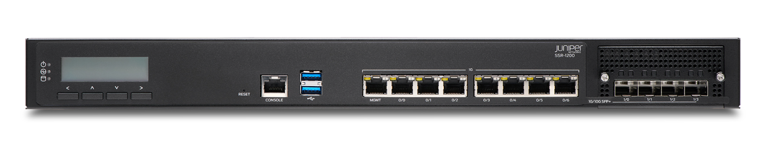
SSR1200—Large branch and small data center or campus deployments |
|
The SSR1200 has seven 1-GbE ports, four 1-GbE/10-GbE SFP+ ports, a management port (for Mist operations), 64-GB of memory, and a 256-GB enterprise-grade solid-state drive (SSD) for storage. |
|
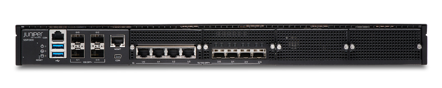
SSR1300—Medium data center or campus deployments |
|
The SSR1300 has four 1-GbE ports, four 1-GbE/10-GbE SFP+ ports, four 10-GbE SFP+ ports, a management port (for Mist operations), 128-GB of memory, and a 256-GB enterprise-grade solid-state drive (SSD) for storage. |
|
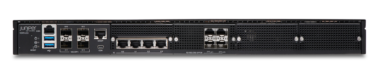
SSR1400—Large data center or campus deployments |
|
The SSR1400 has four 1-GbE ports, four 1-GbE/10-GbE/25-GbE SFP28 ports, four 10-GbE SFP+ ports, a management port (for Mist operations), 256-GB of memory, and a 512-GB enterprise-grade solid-state drive (SSD) for storage. |
|
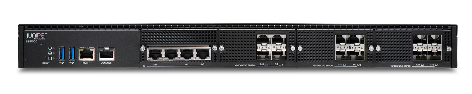
SSR1500—Very large data center or campus deployments |
|
The SSR1500 has four 1-GbE ports, twelve 1-GbE/10-GbE/25-GbE SFP28 ports, a management port (for Mist operations), 512-GB of memory, and a 1 TB enterprise-grade solid-state drive (SSD) for storage. |
Claim Your Device
SSR Series devices are cloud-ready devices; you can manage them using the Juniper Mist™ Cloud portal. To manage the SSR device using Juniper Mist cloud portal, you need to add your SSR devices to your organization’s WAN edge inventory.
To add the SSR device to the WAN edge inventory, do one of the following:
-
Scan the QR code with the Mist AI mobile application. See Use Mist AI App QR Scan.
-
Manually enter the claim code in Mist. See Enter the Mist Activation Code or Claim Code.
The QR code and the Claim Code are located on the rear panel of the chassis in SSR100 Series devices and on the front panel of the chassis in SSR400 Series and SSR1000 Series devices.
The claim code is the number above the QR code. For example: The claim code on the SSR1200 chassis shown in the picture below is K6TAACRTCJWQ8GQ.
|
SSR120 
|
SSR130 
|
|
SSR1200 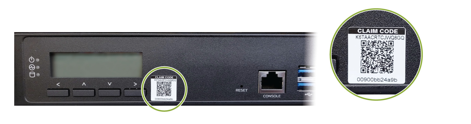
|
SSR1300 
|
|
SSR1400 
|
SSR1500 
|
Use Mist AI App QR Scan
You can download the Mist AI App from the Mac App Store or from Google Play Store.
-
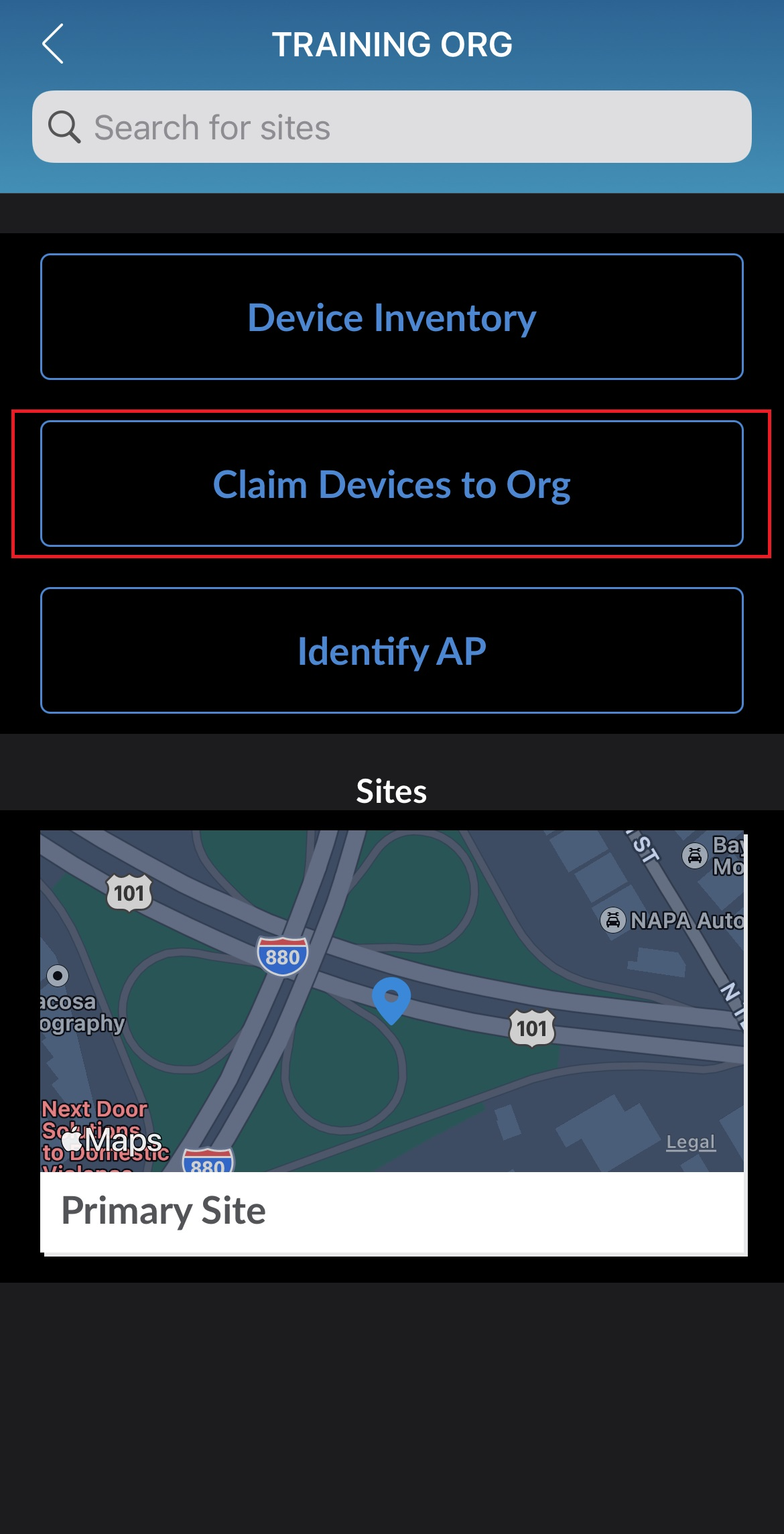
Open the Mist AI app and log in using your account credentials. If you do not have an account, see Create a Mist Account and Organization.
-
Select your organization.
-
Tap Claim Devices to Org.
-
Scan the QR code. The app automatically claims the device and adds it into your organization's inventory.
-
On the Organization screen, tap Device Inventory → Routers → Unassigned.
Review the MAC address.
Onboarding Complete!
Fantastic, the SSR device is in your inventory! To provision the SSR device, see Step 2: Up and Running.
Enter the Mist Activation Code or Claim Code
Claiming multiple devices—When you purchase multiple devices, we provide you with an activation code along with your PO information. Make a note of this code.
Claiming a single device—Locate the QR code on your device and make a note of the alphanumeric claim code directly above it.
-
Open the Juniper Mist™ Cloud portal and log in to your account. If you do not have an account, see Create a Mist Account and Organization.
-
Select Organization > Inventory from the menu on the left, then select the WAN Edges tab at the top.
-
Click Claim WAN Edges in the upper right portion of the inventory screen.
-
Enter the SSR device Activation code or claim code and click Add.

-
Clear the Assign claimed WAN Edges to site check box.
-
Click the Claim button to claim the SSR device into your inventory.
Onboarding Complete!
Fantastic, the SSR device is in your inventory! To provision the SSR device, see Step 2: Up and Running.