ON THIS PAGE
Step 1: Begin
In this guide, we provide a simple, three-step path, to quickly get the Juniper Networks® SSR1500 appliance up and running on Juniper Mist™ cloud. You'll learn how to install, power on, and configure basic settings for an AC-powered SSR1500 appliance.
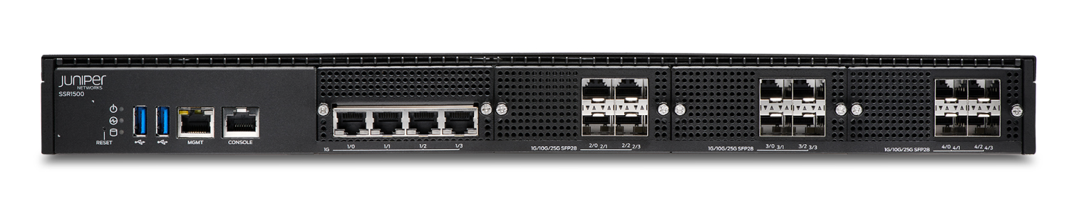
Meet the SSR1500
The SSR1500 is a 1 U fixed configuration appliance that's ideal for large data center or campus deployments. Powered by the Juniper® Session Smart Router (SSR) software, the SSR1500 provides secure and resilient WAN connectivity.
The SSR1500 has four 1 GbE ports, twelve 1/10/25 GbE SFP28 ports, a management port (for Mist operations), 512 GB of memory, and a 1 TB enterprise-grade solid-state drive (SSD) for storage.
Install the SSR1500
What's in the Box?
Along with your SSR1500, you’ll find:
-
RJ-45 to USB A serial cable
-
AC power cord (country-specific)
-
Rack mount kit
-
Two front mounting brackets
-
Two side mounting rails
-
Two rear mounting blades
-
Six M4 i-head screws (for the front mounting brackets)
-
Ten rack screws and cage nuts
-
Eight M4 flat-head screws
-
What Else Do I Need?
-
Number 2 or 3 Phillips (+) screwdriver, depending on the size of your rack screws
-
A management host such as a laptop or desktop PC
-
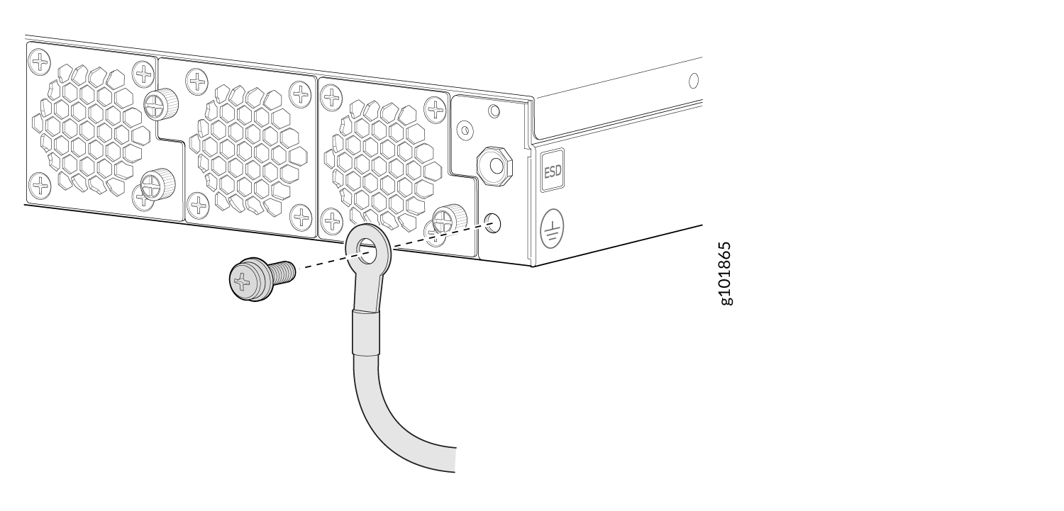
A grounding cable
Ensure that a licensed electrician has attached the appropriate grounding lug to your grounding cable. Using a grounding cable with an incorrectly attached lug can damage the SSR1500.
Rack It
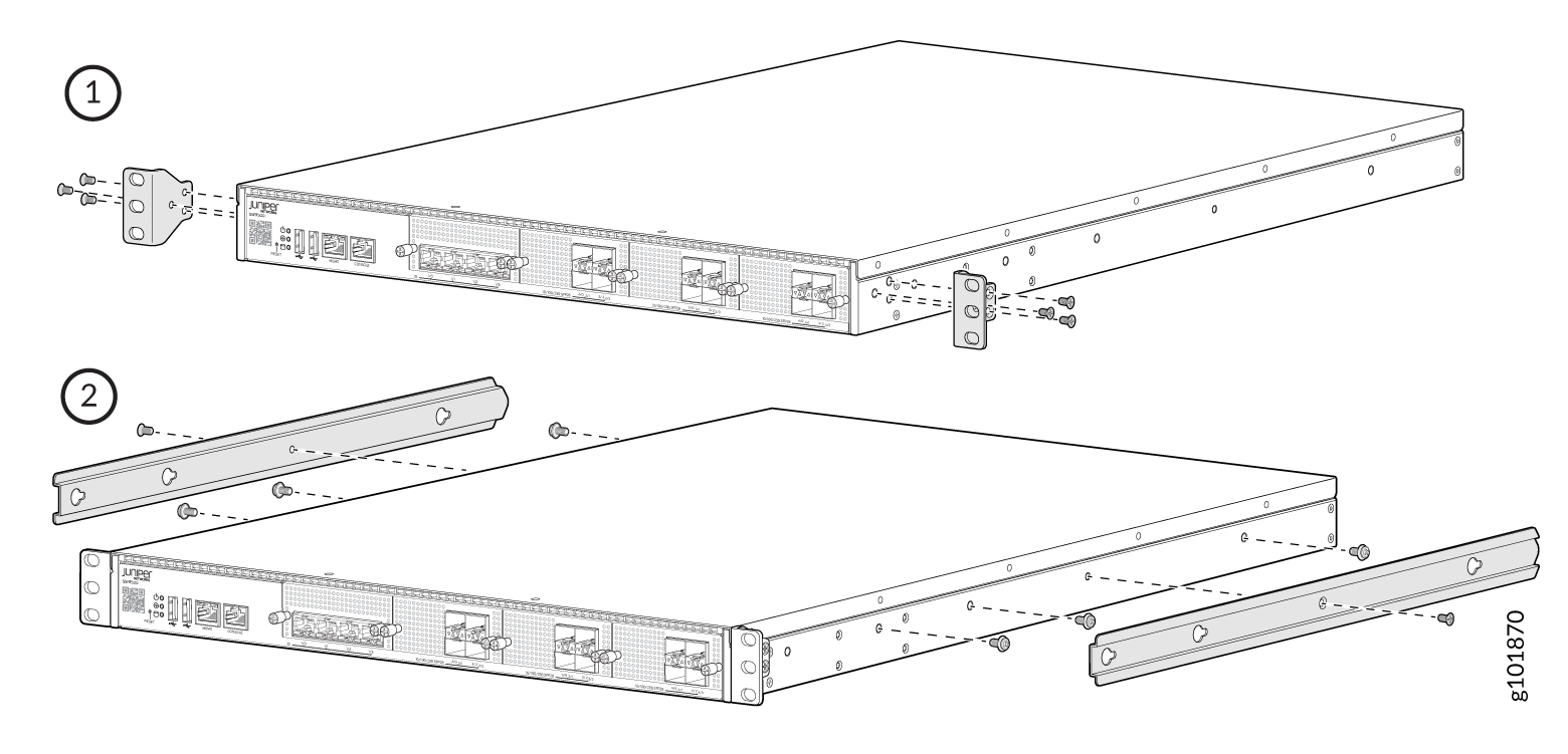
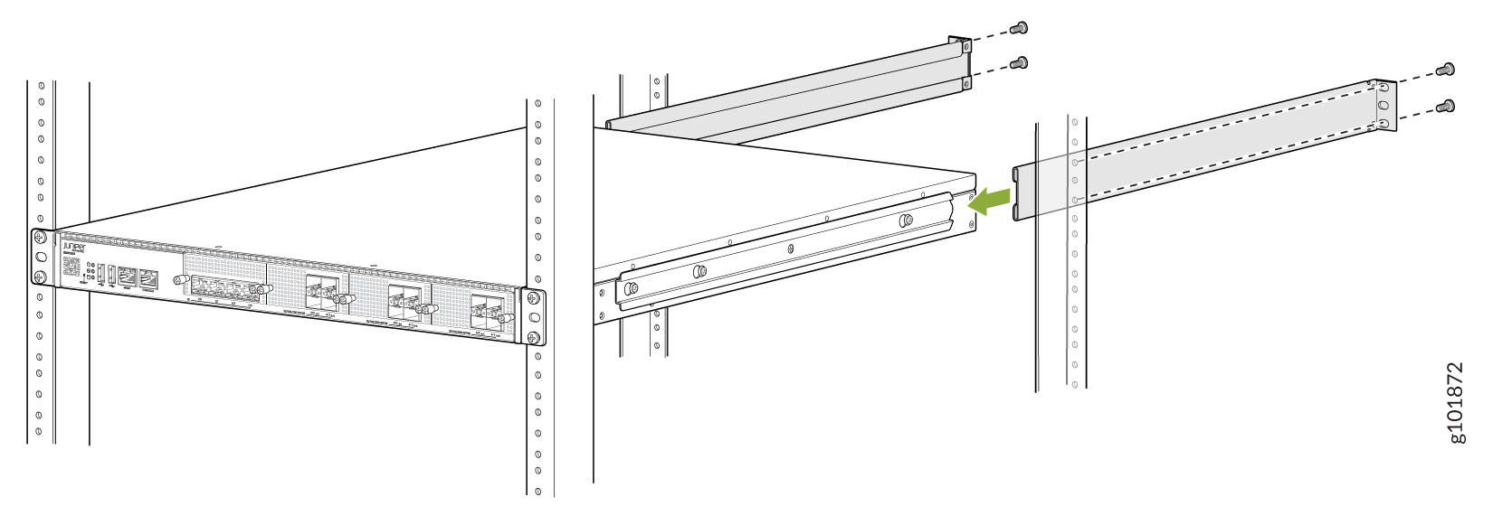
Here’s how to install the SSR1500 in a four-post rack:
-
Secure the six M4 i-head screws to the sides of the chassis. Position the
side mounting rails such that the keyholes of the side mounting rails align
with the M4 i-head screws on the chassis. Slide and lock the side mounting
rails in place and use the two M4 flat-head screws to secure the
rails.
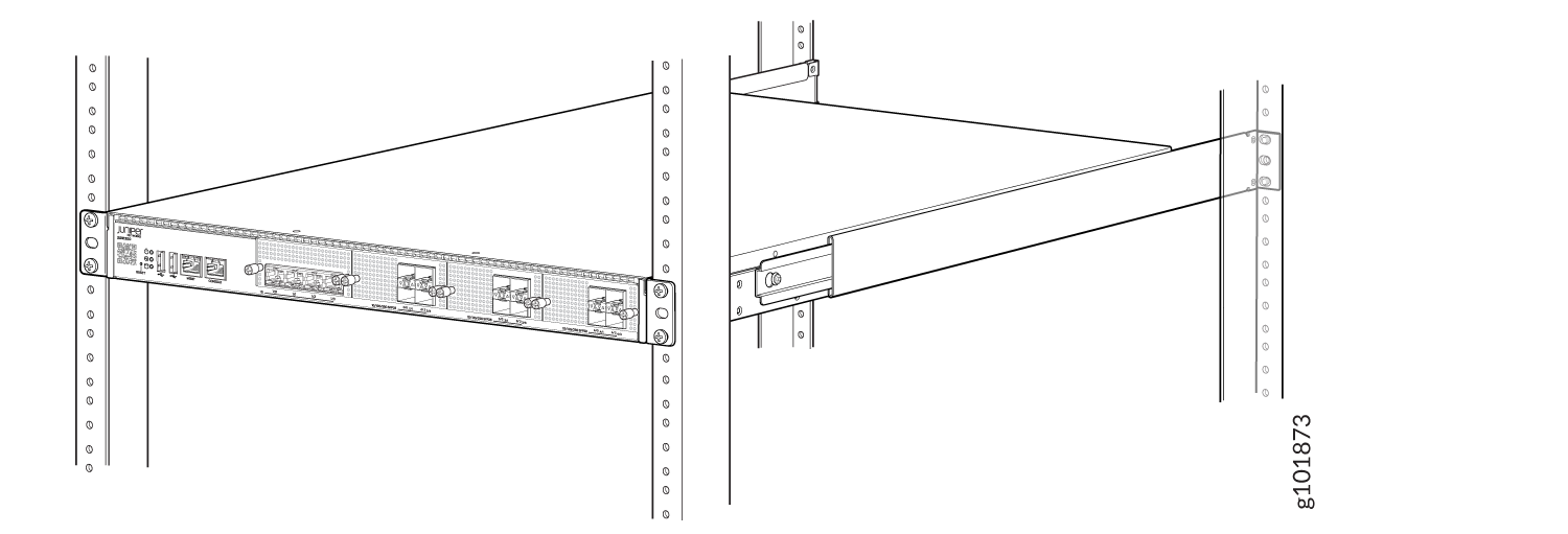
-
While you’re holding the SSR1500 in place, have a second person insert and
tighten the rack-mount screws to secure the front mounting brackets to the
rack rails. Tighten the screws in the two bottom holes first, then tighten
the screws in the two top holes.
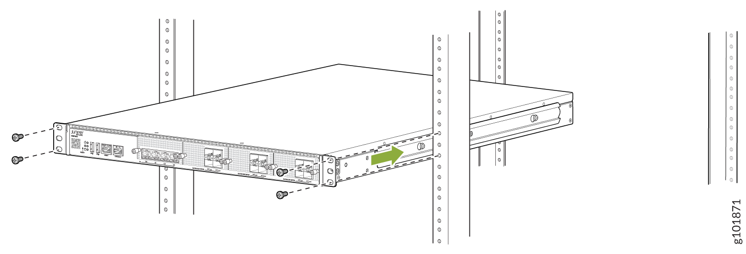
-
Secure the rear mounting blades on each side of the chassis to the rack
post using the rack mounting screws.
-
Check that the front mounting brackets on each side of the rack are lined
up with each other.
-
Attach a grounding cable to earth ground and then attach the other end to
the SSR1500 grounding point.
Power On
Now that you’ve installed your SSR1500 in the rack and grounded the chassis, you’re ready to connect it to power.
If you want to connect your SSR1500 to the Mist Cloud, you must connect the Ethernet/transceiver cable to your preferred management port (MGMT or other) before powering on the appliance. The Ethernet/transceiver cable must provide connectivity to the internet or to your Mist Cloud instance.
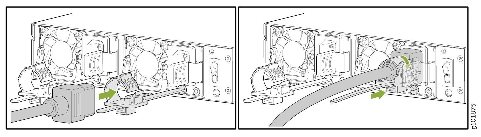
The SSR1500 supports redundant AC power supplies that are pre-installed at the factory. It comes with two AC power supplies preinstalled on the rear of the device.
-
Slide the loop toward the power supply socket until it is snug against the
base of the coupler.