Step 1: Begin
In this guide, we provide a simple, three-step path, to quickly get you up and running with your new SRX4600. We’ve simplified and shortened the installation and configuration steps, and included how-to videos. You’ll learn how to install the SRX4600 in a rack, power it up, and deploy it on your network.
You can use either Juniper Routing Director (formerly Juniper Paragon Automation) or the device CLI to deploy the SRX4600 to the network.
To mount, connect power to, and perform initial configuration on the SRX4600 Firewall, you need:
-
Electrostatic discharge (ESD) grounding strap (not provided)
-
Four-post rack-mounting kit (provided)
-
Twelve screws to secure the mounting rails to the chassis (provided)
-
Eight screws to secure the chassis to the rack (not provided)
-
Screwdriver appropriate for your rack-mounting screws (not provided)
-
Two AC power cords with plugs appropriate for your geographical location (provided)
-
Management host, such as a PC or laptop, with a serial port (not provided)
-
A grounding cable (minimum 14 AWG (2 mm²), minimum 90°C wire), a grounding lug (Panduit LCD10-10A-L or equivalent) (not provided).
-
RJ-45 cable and RJ-45 to DB-9 serial port adapter (not provided)
Note:We no longer include the console cable as part of the device package. If the console cable and adapter are not included in your device package, or if you need a different type of adapter, you can order the following separately:
-
RJ-45 to DB-9 adapter (JNP-CBL-RJ45-DB9)
-
RJ-45 to USB-A adapter (JNP-CBL-RJ45-USBA)
-
RJ-45 to USB-C adapter (JNP-CBL-RJ45-USBC)
If you want to use an RJ-45 to USB-A or RJ-45 to USB-C adapter, you must have the X64 (64-Bit) Virtual COM port (VCP) driver installed on your PC. See https://ftdichip.com/drivers/vcp-drivers/ to download the driver.
-
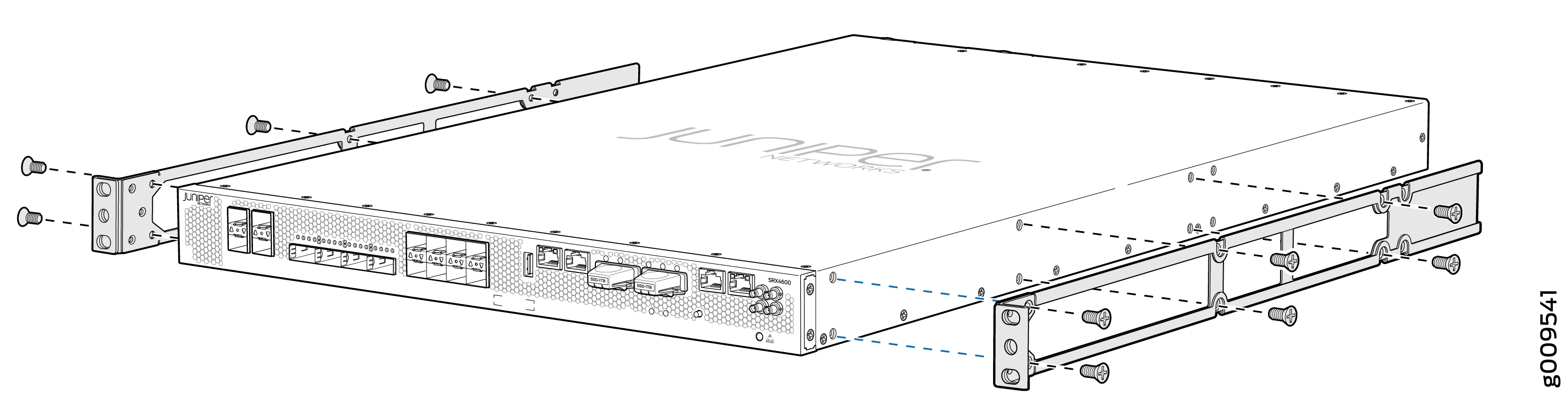
Mount the SRX4600
You can mount an SRX4600 Firewall in a 19-inch four-post rack configuration. An AC device weighs approximately 38 lb (17.23 kg) and a DC device weighs approximately 40 lb (18.14 kg). Two persons are required for mounting the device.
To mount the firewall:
-
Align the holes in the side mounting rails with the holes on the side of
the chassis and attach the side mounting rails to the chassis by using the
mounting screws.
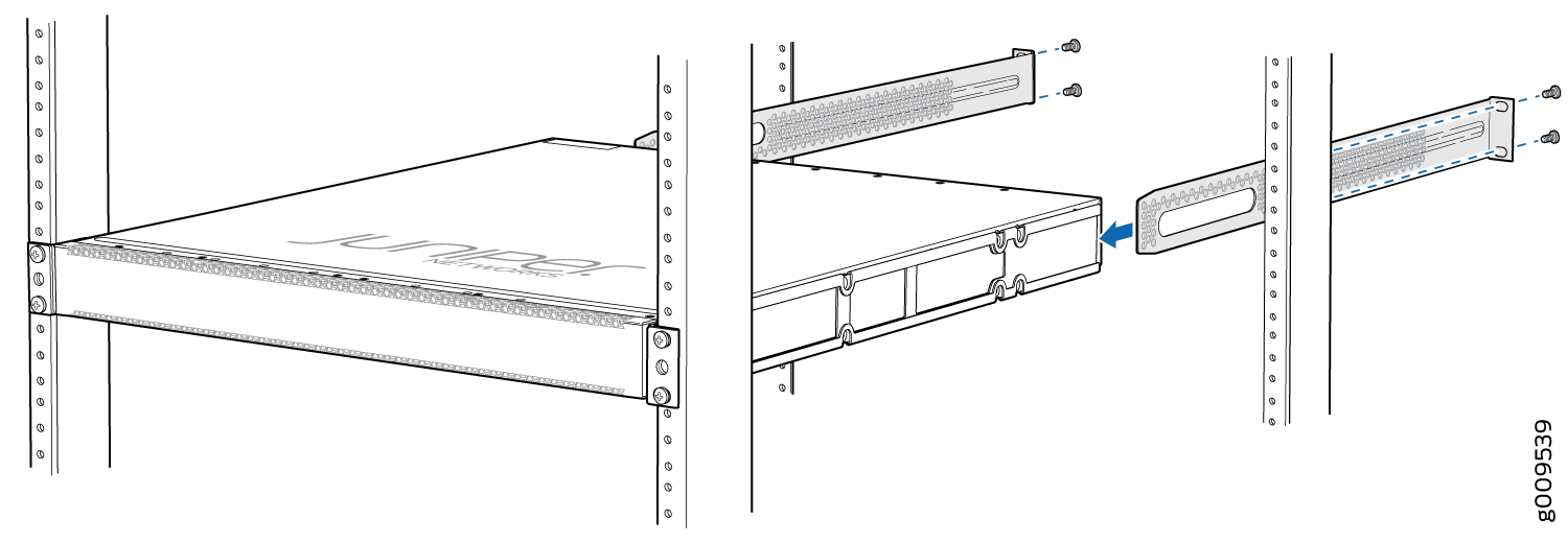
-
Have the second person use the mounting screws (and cage nuts and washers
if your rack requires them) to screw the mounting bracket to the rack.
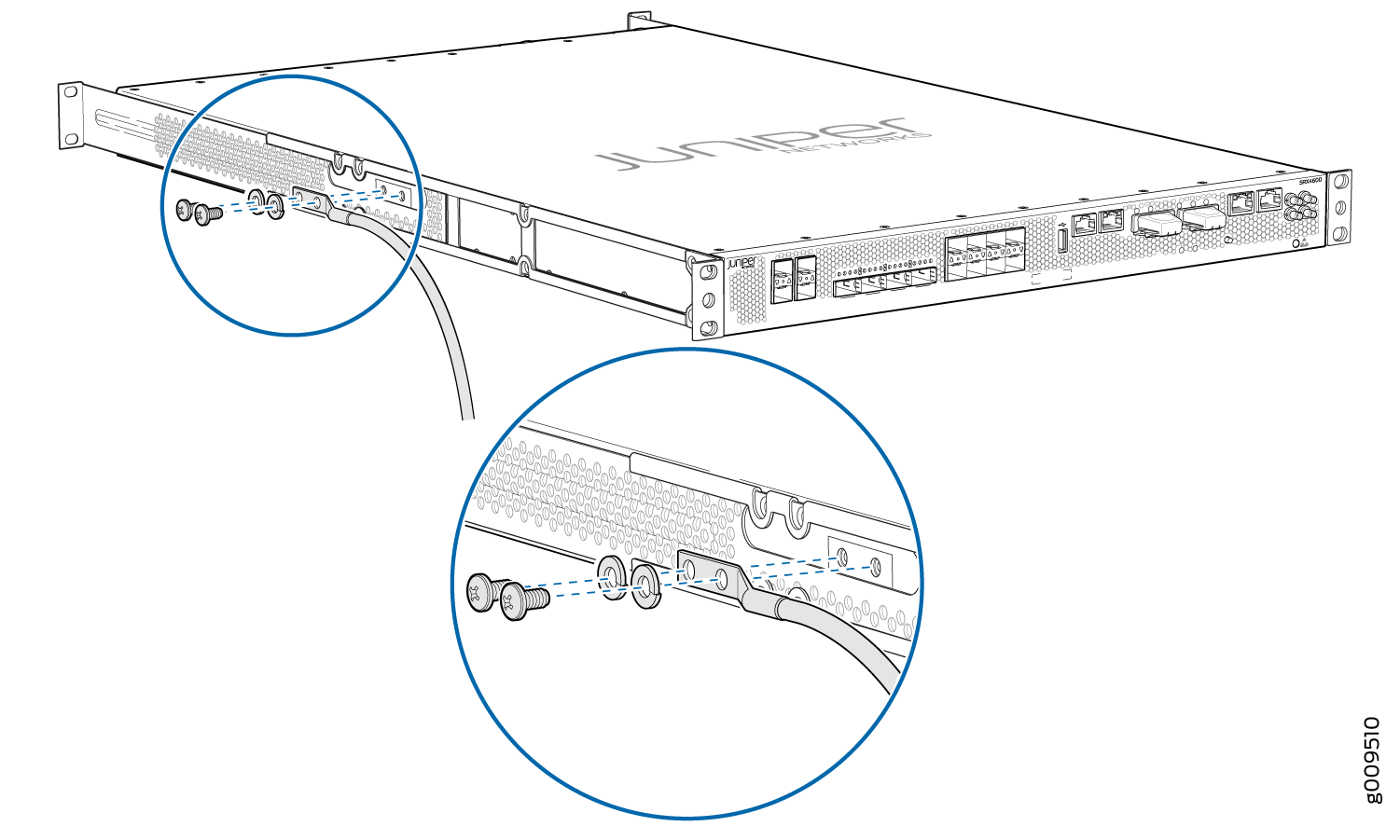
Connect the SRX4600 to Ground
To connect the Firefall to the ground:
-
Secure the grounding lug to the protective earthing terminal with the
washers and screws.
Connect Power to the SRX4600
Check if the power supplies AC or DC are fully inserted into the chassis.
Connect Power to an AC-powered SRX4600
To connect power to an AC-powered Firewall:
An AC-powered device gets additional grounding when you connect the power supply in the device to a grounded AC power outlet by using the power cord.
-
Insert the coupler end of the power cord into the AC power cord inlet on the AC power supply faceplate. Push the power cord retainer onto the power cord.
-
Insert the power cord plug into an AC power source outlet:
-
If the AC power source outlet has a power switch, set it to on (|) position and the Firewall will power on.
-
If there is no power switch on the AC power source outlet, the firewall will power on instantly.
-
-
Verify that the OK/FAIL LED is lit green and on steadily.
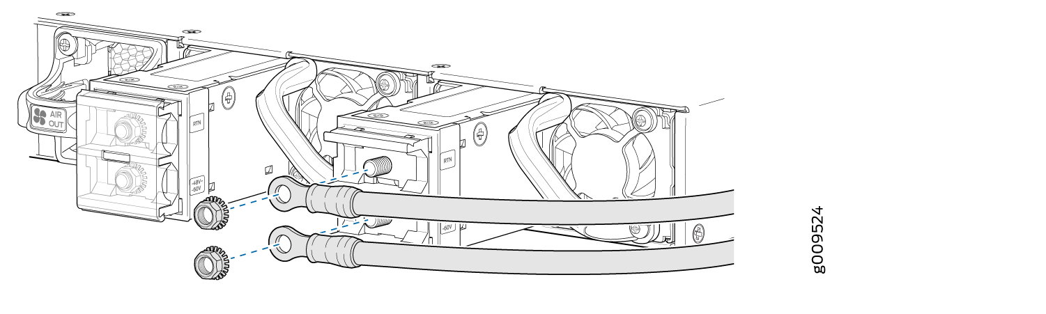
Connect Power to a DC-powered SRX4600
To connect power to a DC-powered Firewall:
Before performing the following procedure, ensure that there is no power in the DC circuit. To ensure that all power is cut off, locate the circuit breaker on the panel board that services the DC circuit, switch the circuit breaker to the off (0) position, and tape the switch handle of the circuit breaker in the off position.
-
Ensure that the voltage across the DC power source cable leads is 0 V and that the cable leads do not become active while you are connecting DC power.
-
Verify that the DC power cables are correctly labeled before connecting them to the power supply. In a typical power distribution scheme where the return is connected to chassis ground at the battery plant, you can use a multimeter to verify the resistance of the –48V and RTN DC cables to chassis ground:
-
The cable with very high resistance (indicating an open circuit) to chassis ground is negative (–) and is installed on the –48V (input) DC power input terminal.
-
The cable with very low resistance (indicating a closed circuit) to chassis ground is positive (+) and is installed on the RTN (return) DC power input terminal.
-
-
Remove the protective cover from the DC power input terminal block. Save this cover for future use.
-
Remove the M5 K-nuts from each DC power input terminal.
-
Attach DC terminal rings (TYCO 2-36161-2 Terminal Ring, number 10, not provided) to the ends of the DC power cables. Crimp tightly.
-
Insert the DC terminal rings into the DC power input terminals and secure the DC terminal rings with M5 K-nuts. Do not overtighten.
-
Replace the protective cover over the input terminal block.
-
Remove the tape from the switch handle of the circuit breaker on the panel board that services the DC circuit, and switch the circuit breaker to the ON (|) position.
-
Verify that the OK/FAIL LED is lit green and on steadily.