Fast Track to Rack Installation and Power
This procedure walks you through the most basic steps for installing your QFX5700 switch in a rack and connecting it to power.
You can install the QFX5700 switch on a four-post rack or by using a mechanical lift. We’ll walk you through the steps to install the QFX5700 switch manually.
For information on installation of four-post rack by using a mechanical lift, see Installing a QFX5700 Switch using a Mechanical Lift.
Before you install the switch, review:
Manually Mount a QFX5700 Switch on a Four-Post Rack
To manually mount a QFX5700 switch in a Four-Post Rack:
The switch weighs approximately 250 lb (113 kg). Lifting the chassis and mounting it in a rack or cabinet requires at least three people. Make sure the chassis is empty (contains only the midplane) before you lift it.
Before you install the switch, remove the pre-installed FRUs:
-
Remove a QFX5700 Routing and Control Board (RCB).
-
Remove a QFX5700 Forwarding Engine Boards (FEB).
-
Remove a QFX5700 FPCs.
-
Remove a QFX5700 Fan Tray.
-
Remove an AC/HVDC Power Supply or remove a DC Power Supply:
Be sure that you have the following parts and tools available to install the switch:
-
Eighteen mounting screws appropriate for your rack (not provided)
-
A Phillips (+) screwdriver, number 1, 2, or 3, depending on the size of your rack-mounting screws.
To manually install the switch in the rack or cabinet:
-
Wrap and fasten one end of the ESD wrist strap around your bare wrist, and connect the other end of the strap to the ESD point on the device.
-
Using a Phillips screwdriver, remove the screw on each side of the chassis that holds the rear mounting-blades to the chassis.
Slide the mounting blades out of the channels.
Figure 1: Removing the Rear-Mounting Blades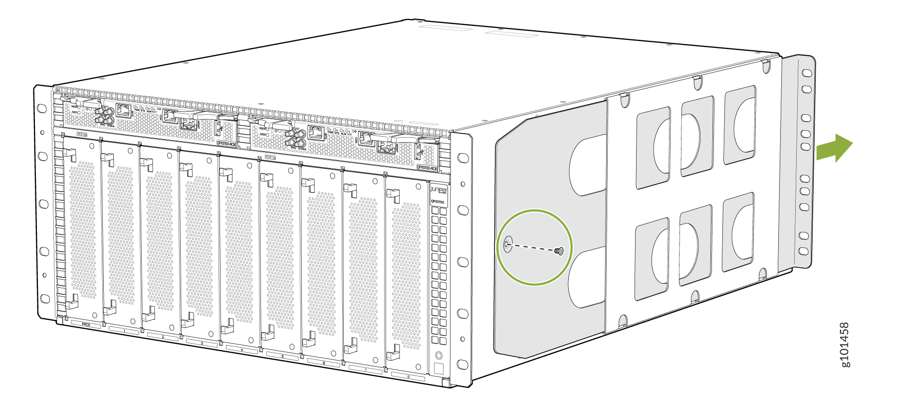
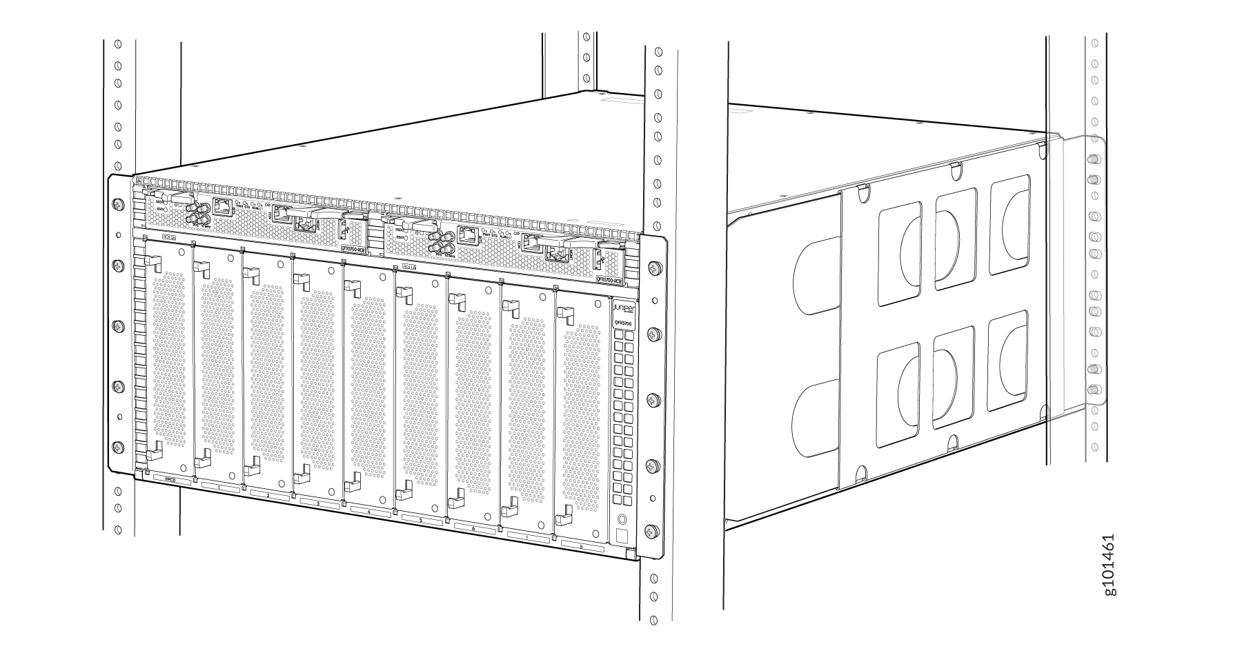
With one person on each side, hold on to the bottom of the chassis. Carefully lift the chassis and position it in the rack so that the front brackets are aligned with the rack holes.
Figure 2: Lift the Chassis by Hand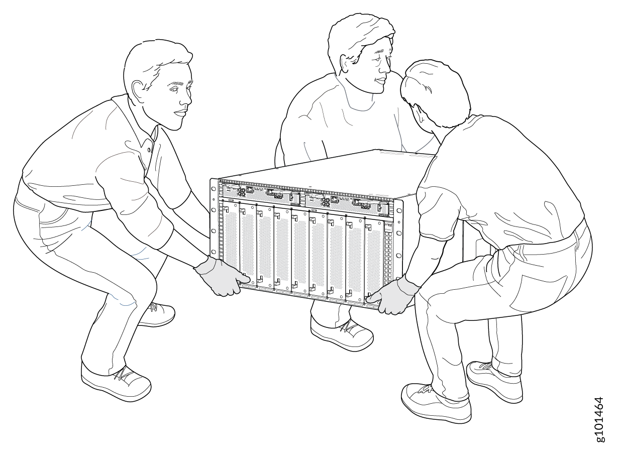 Figure 3: QFX5700 Switch Installed in a Four-Post Rack
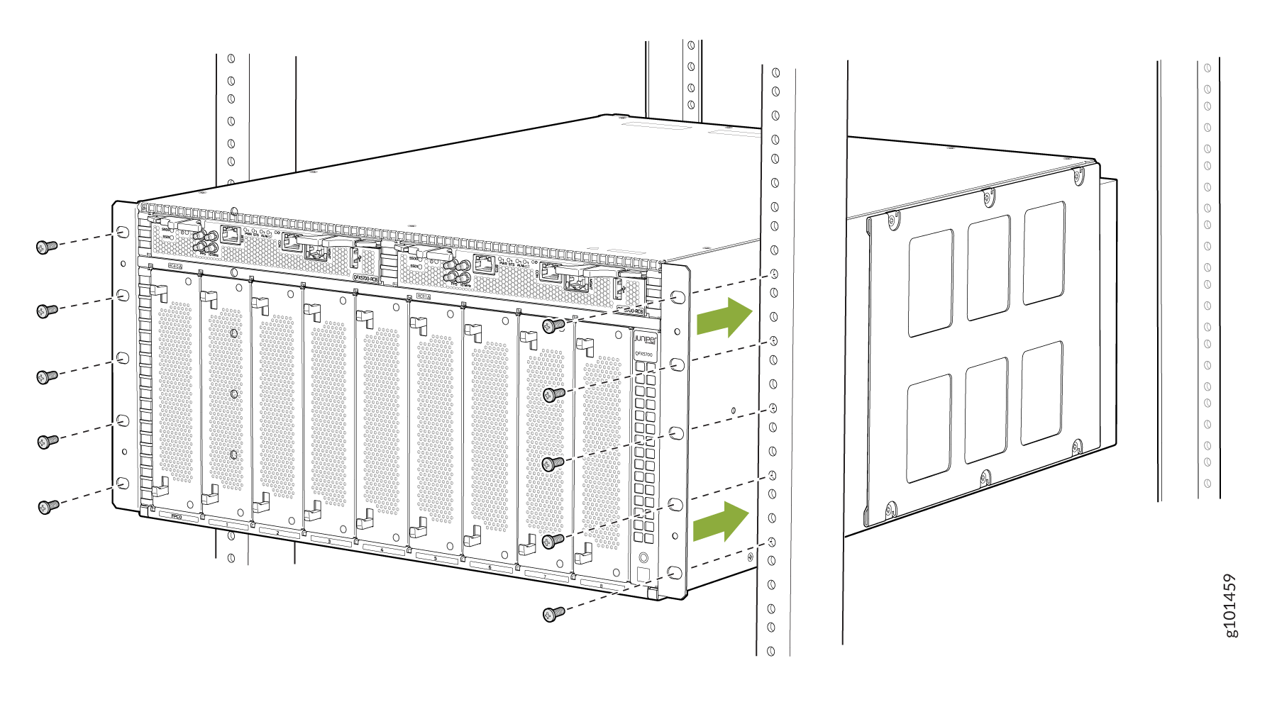
-
With two people continuing to support the chassis the third person can install mounting screws into each of the front-mounting bracket holes aligned with the rack, starting from the bottom, and tighten the screws.
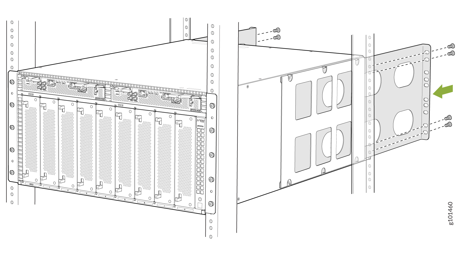
On the rear of the chassis, slide the rear-mounting blades into the channels on either side of the chassis until the rear-mounting brackets at the end of the blades contact the rack rails
-
Install mounting screws into each of the rear-mounting bracket holes aligned with the rack, starting from the bottom, and secure it tightly.
Visually inspect the alignment of the chassis. If you’ve installed the chassis properly in the rack, all the mounting screws on one side of the rack are aligned with the mounting screws on the opposite side, and the switch is level.
-
If you have removed any pre-installed FRUs, reinstall the same:
-
Install a QFX5700 RCB
-
Install a QFX5700 FEB
-
Install a QFX5700 FPCs
-
Install a QFX5700 Fan Tray
-
Install an AC/HVDC Power Supply/DC Power Supply
-
-
Connect to Power
To connect the QFX5700 switch to AC power, you must perform the following tasks:
Connect the QFX5700 Switch to Earth Ground
To meet safety and electromagnetic interference (EMI) requirements and to ensure proper operation, you must connect the chassis to earth ground before you connect it to power.
You must install the QFX5700 in a restricted-access location and ensure that the chassis is always properly grounded. The QFX5700 has a two-hole protective grounding terminal provided on the chassis. Under all circumstances, use this grounding connection to ground the chassis. For AC-powered systems, you must also use the grounding wire in the AC power cord along with the two-hole grounding lug connection. This tested system meets or exceeds all applicable EMC regulatory requirements with the two-hole protective grounding terminal.
If an external ground connection is required, ensure that a licensed electrician has attached an appropriate grounding lug to the grounding cable you supply. Using a grounding cable with an incorrectly attached lug can damage the switch.
Mount your switch in the rack before attaching the grounding lug to the switch.
Ensure that you have the following parts and tools available:
-
An electrostatic discharge (ESD) grounding strap (provided)
-
Protective earthing terminal lug (provided)
-
Grounding cables for your QFX5700 (not provided)—The grounding cable must be 4 AWG (21.1 mm²) stranded wire should be rated 90°C or per local electrical code.
-
Grounding lug for your grounding cable (not provided)—This bracket attaches to the lower left corner of the switch chassis next to the bottom power supply, providing a protective earthing terminal for the switch. The grounding lug required is a Panduit LCD6-14A-L or equivalent.
-
A number 3 Pozidriv or Phillips screwdriver (not provided) to tighten the two screws that are mounted on the chassis.
You need to use terminal lugs that are Panduit LCD4-14A-L, or equivalent, and sized for 4 AWG (21.1 mm2) power source cables. The 4 AWG (21.1 mm²) stranded wire should be rated 90°C or per local electrical code. We recommend that you install heat-shrink tubing insulation around the crimped section of the power cables and lugs.
An AC-powered QFX5700 gets additional grounding when you plug the power supply in the switch into a grounded AC power outlet by using an AC power cord appropriate for your geographical location.
To connect earth ground to a QFX5700:
-
Wrap and fasten one end of the ESD grounding strap around your bare
wrist and connect the other end of the strap to one of the ESD points on
the chassis. See Figure 4.
Figure 4: ESD Point for the QFX5700
 1—
1—ESD point
-
Place the chassis grounding lug and cable over the screw holes with the
cable connection pointing to the left. See Figure 5.
Figure 5: Connect a Grounding Cable to the QFX5700

Connect AC Power to a QFX5700
Before you begin to connect power to the switch, be sure you understand how to prevent ESD damage. See Prevention of Electrostatic Discharge Damage.
To meet safety and EMI requirements and to ensure proper operation, you must connect the QFX5700 switch to earth ground before you connect it to power.
Before you connect power to the switch, a licensed electrician must attach a cable lug to the grounding and power cables that you supply. A cable with an incorrectly attached lug can damage the switch (for example, by causing a short circuit). To meet safety and EMI requirements and to ensure proper operation, you must connect the chassis to earth ground before you connect it to power. For installations that require a separate grounding conductor to the chassis, use the protective earthing terminal on the switch chassis to connect to the earth ground. The switch gains additional grounding when you plug the PSM in the switch to a grounded AC power outlet by using the AC power cord appropriate for your geographical location.
The AC power supply unit (PSUs) in a QFX5700 switch is a hot-removable and hot-insertable field-replaceable unit (FRU). You can remove and replace it without powering off the switch or disrupting routing functions. Since the power supplies in the QFX5700 switch aren't zoned, any 2 slots can be used to place PSUs in its chassis.
To connect AC power to a QFX5700 chassis:
To connect AC power to a QFX5700 switch:
Wrap and fasten one end of the ESD wrist strap around your bare wrist, and connect the other end of the strap to the ESD point on the device.
Ensure that the power supplies are fully inserted in the chassis and the latches are secure.
Locate the AC power cords shipped with the QFX5700 switch; the cords have plugs appropriate for your geographical location.
Insert the coupler end of the power cord into the AC power cord inlet on the AC power supply faceplate.
Figure 6: Connecting an AC Power Cord to the QFX5700 Figure 7: Connecting an AC Power Cord to the QFX5700
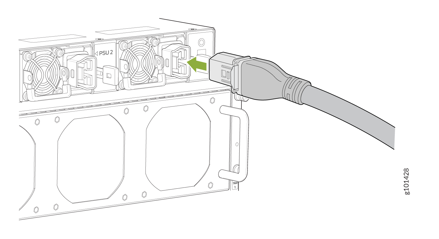
If the AC power source outlet has a power switch, set it to the off (O) position.
Note:The QFX5700 powers on as soon as power is provided to the PSU. The PSU has no power switch.
Insert the power cord plug into an AC power source outlet.
If the AC power source outlet has a power switch, set it to the on (|) position.
Verify that the status LEDs on each power supply are lit green. Verify that the status LEDs on each power supply are lit green