Fast Track to Rack Installation and Power
This procedure guides you through the steps to install your AC-powered ACX7509 router in a rack using a mechanical lift and connect it to power.
You can install a ACX7509 router into a four-post rack or a cabinet by using a mechanical lift, or you can install it manually. See Manually Mount an ACX7509 Router in a Four-Post Rack.
Complete the following prerequisites before you install the router:
-
Prepare the site for installation as described in Site Preparation Checklist for ACX7509 Routers.
-
Be sure the site has adequate clearance for both airflow and hardware maintenance, as described in Clearance Requirements for Airflow and Hardware Maintenance of ACX7509 Routers.
-
Unpack the router as described in Unpack an ACX7509 Router.
Do not install FPCs in the chassis until after you mount the chassis securely on a rack or in a cabinet.
Before mounting the router on a rack or in a cabinet, have a qualified technician verify that the rack or cabinet is strong enough to support the router's weight. Have the technician verify also that the rack or cabinet is adequately supported at the installation site.
If you are installing more than one router on a rack or in a cabinet, install the first router at the bottom of the rack.
Mount an ACX7509 in a Four-Post Rack Using a Mechanical Lift
Be sure that you have the following parts and tools available to install the router:
-
A mechanical lift rated for 250 lb (113.4 kg)
-
Twenty mounting screws appropriate for your rack (not provided)
-
A Phillips (+) screwdriver, number 1, 2, or 3, depending on the size of your rack-mounting screws
Because of the router's size and weight, we strongly recommend that you use a mechanical lift to install the ACX7509 router.
To install the router using a mechanical lift:
-
Wrap and fasten one end of the ESD wrist strap around your bare wrist, and connect the other end of the strap to the ESD point on the device.
-
Using a Phillips screwdriver, remove the screw on each side of the chassis that holds the rear-mounting blades to the chassis.
-
Slide the mounting blades out of the channels.

-
Load the router onto the lift, making sure it rests securely on the lift platform.

-
Using the lift, align the router in front of the rack.
-
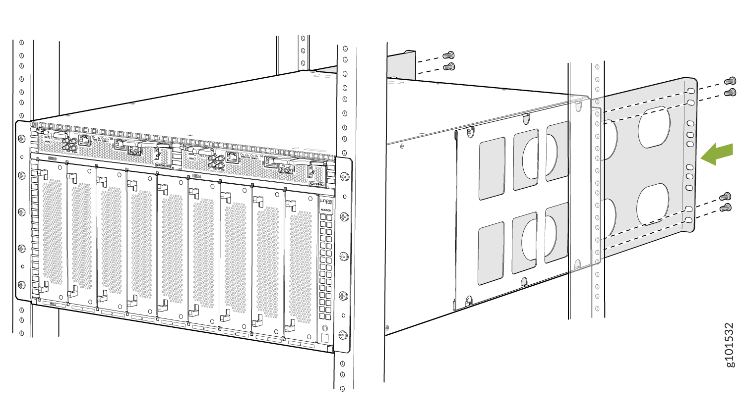
Carefully position the chassis in the rack until the holes of the front-mounting brackets align with the holes in the rack rails.

-
Install mounting screws into each of the front-mounting bracket holes aligned with the rack, starting from the bottom, and tighten the screws.
-
On the rear of the chassis, slide the rear-mounting blades into the channels on either side of the chassis until the rear-mounting brackets at the end of the blades contact the rack rails.
-
Install mounting screws into each of the rear-mounting bracket holes aligned with the rack, starting from the bottom, and secure them tightly.
-
Visually inspect the alignment of the chassis.
If you’ve installed the chassis properly in the rack, all the mounting screws on one side of the rack are aligned with the mounting screws on the opposite side, and the router is level.

-
Move the lift away from the rack.
-
If you have removed any pre-installed FRUs, reinstall them.
Connect to Power
To connect the ACX7509 router to AC power:
Ground the ACX7509 Router
Before you connect an earth ground to the protective earthing terminal of an ACX7509 router, ensure that a licensed electrician has attached an appropriate grounding lug to the grounding cable.
An AC-powered ACX7509 router chassis gains additional grounding when you plug the power supply into a grounded AC power outlet by using an AC power cord appropriate for your geographical location.
Ensure that you have the following parts and tools available:
-
An electrostatic discharge (ESD) grounding strap (provided).
-
Protective earthing terminal lug (provided).
-
Grounding cable for your router—The grounding cable must be 4 AWG (21.2 mm²) stranded wire should be rated 90° C or per local electrical code.
-
Grounding lug for your grounding cable (not provided)—This bracket attaches to the lower left corner of the router chassis next to the bottom power supply, providing a protective earthing terminal for the router. The grounding lug required is a Panduit LCD6-14A-L or equivalent.
-
A Phillips screwdriver (not provided) to tighten the two screws that are mounted on the chassis.
The Panduit LCD4-14A-L terminal lugs, or equivalent are sized for 4 AWG (21.1 mm2) power source cables. The 4 AWG (21.1 mm²) stranded wire should be rated 90° C or per local electrical code. We recommend that you install heat-shrink tubing insulation around the crimped section of the power cables and lugs.
To ground the ACX7509 router:
Verify that a licensed electrician has attached the cable lug provided with the router to the grounding cable.
Ensure that all grounding surfaces are clean and shiny before making the grounding connections.
Connect the grounding cable to a proper earth ground, such as the rack in which the router is mounted.
Wrap and fasten one end of the ESD grounding strap around your bare wrist and connect the other end of the strap to one of the ESD points on the chassis.
Remove the two M6 screws with attached washers on the chassis using a Phillips screwdriver.
Place the chassis grounding lug and cable over the screw holes with the cable connection pointing to the left.
Place the two screws with attached washers over the grounding lug and grounding cable.
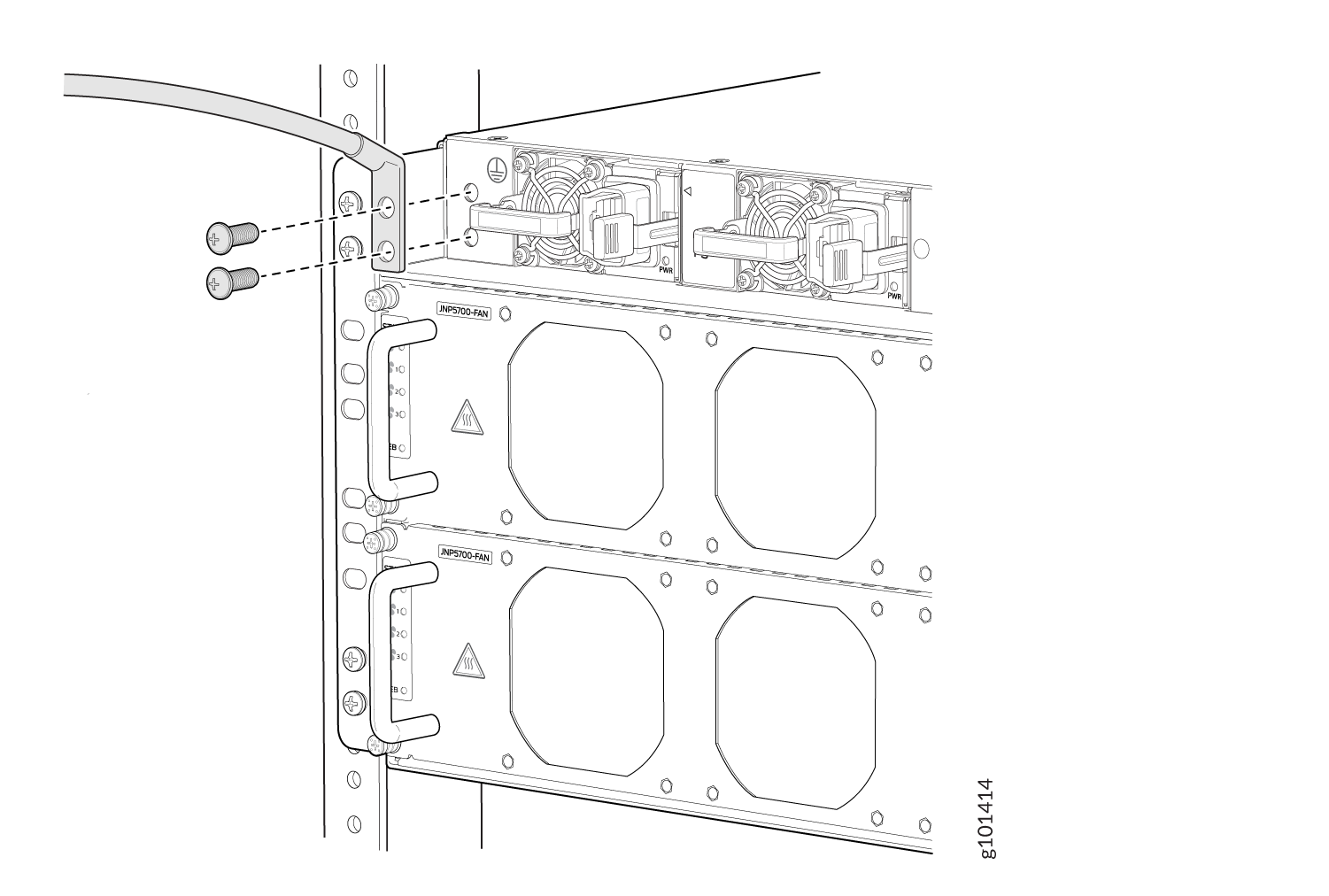
Secure the grounding cable lug with the M6 screws attached with washers.
Verify that the grounding cable does not touch or block access to router components, and make sure that it does not trail across the floor where people could trip over it.
Connect the Power Cord and Power On the Router
For information about the supported AC power cord specifications, see ACX7509 AC/HVDC Power Cord Specifications.
To connect AC power to an ACX7509 router:
-
Ensure that you have a power cord appropriate for your geographical location available to connect AC power to the router.
-
Read General Electrical Safety Guidelines and Warnings and Action to Take After an Electrical Accident .
-
Ensure that you have an ESD grounding strap.
-
If not already installed, install the power supplies in the router.
Each power supply must be connected to a dedicated power source outlet.
Wrap and fasten one end of the ESD wrist strap around your bare wrist, and connect the other end of the strap to the ESD point on the device.
Ensure that the power supplies are fully inserted into the chassis and the latches are secure.
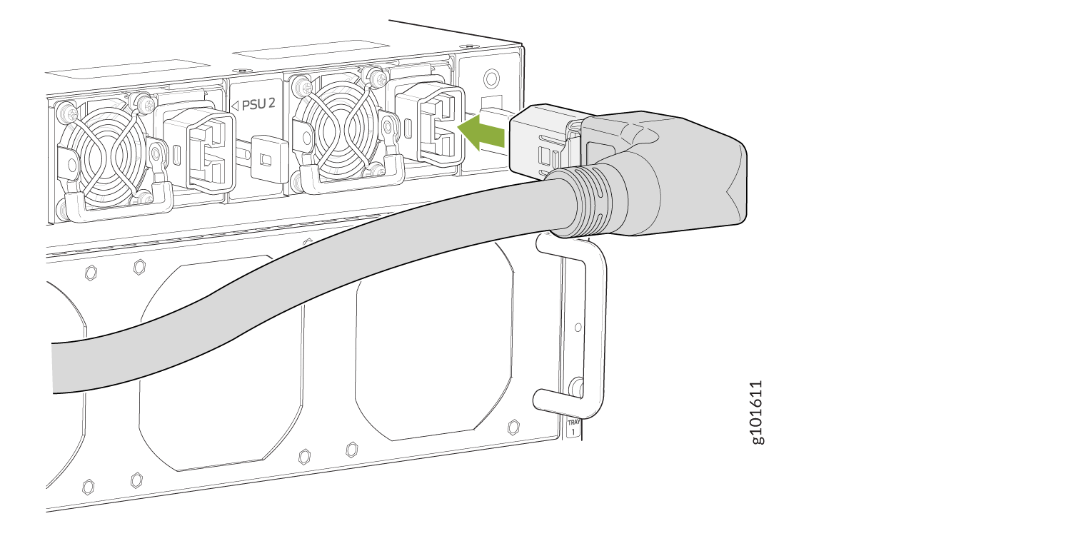
Locate the AC power cords shipped with the ACX7509 router; the cords have plugs appropriate for your geographical location.
Insert the coupler end of the power cord into the AC power cord inlet on the AC power supply faceplate.
If the AC power source outlet has a power switch, set it to the off (O) position.
Insert the power cord plug into an AC power source outlet.
Note:The ACX7509 router powers on as soon as power is provided to the PSM. There is no power switch on the router.
If the AC power source outlet has a power switch, set it to the on (|) position.
Verify that the status LEDs on each power supply are lit green.
If the status LED is lit amber, remove power from the power supply, and replace the power supply. Do not remove the power supply until you have a replacement power supply ready.