
Install the SSR440 Routers
This topic guides you through the steps to install an SSR440 Router on a desk or other level surface or mount each router in a two-post rack.
You can mount an SSR440 Router on a desk or other level surface. Alternatively, you can mount each of these routers in a two-post rack, using the separately orderable rack mount kit shipped with the router.
Complete these prerequisites before you mount the router:
-
Prepare the site for installation as described in the Site Guidelines and Requirements.
-
Ensure that the site has adequate clearance for both airflow and hardware maintenance.
Figure 1: Clearance Requirements for the SSR440 Routers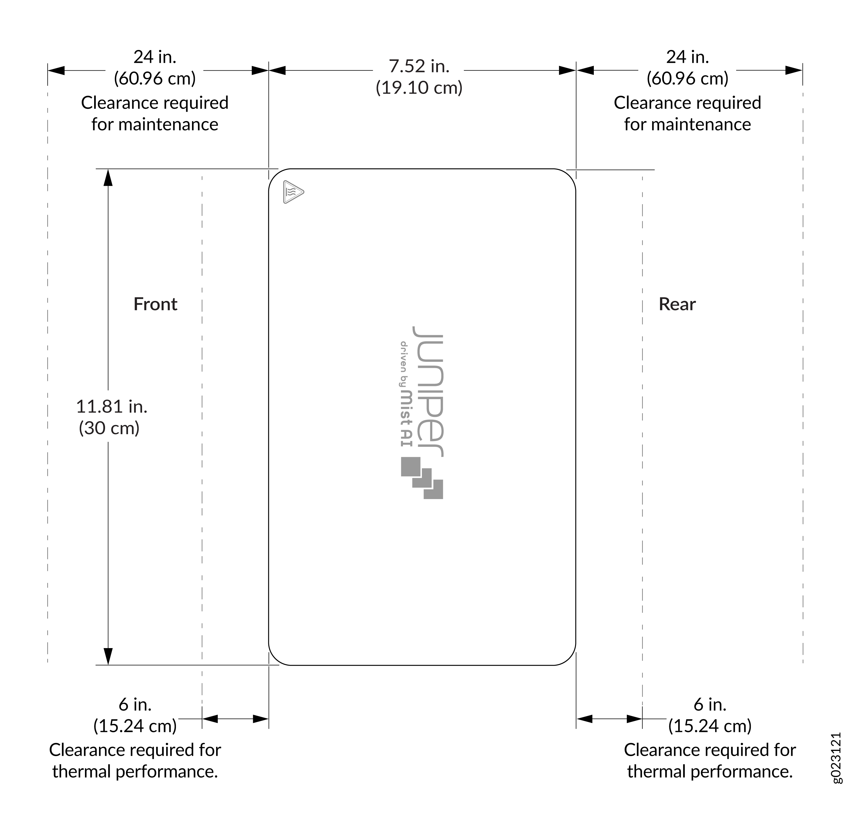
-
Unpack the device as described in Unpack the SSR440.
Ensure that you support the rear of the chassis throughout the process of mounting the appliance on the rack.
A qualified technician must verify that the rack or cabinet is strong enough to support the device's weight before mounting the device. Have the technician also verify that the rack or cabinet has adequate support at the installation site.
If you are installing more than one device on a rack or in a cabinet, install the first device at the bottom of the rack.
Install the SSR440 Routers
Before you install, review the following:
You can mount SSR440 Routers:
On a desk or other level surface using rubber feet.
On a two-post rack or cabinet using the separately orderable SSR400-RMK rack mount kit.
We’ll walk you through the steps to mount the router on a desk or other level surface or to mount the router on a two-post rack.
Mount an SSR440 on a Desk or Other Level Surface
Ensure that you have the following parts and tools available:
-
Four rubber feet to stabilize the chassis on a desk or other level surface (provided)
-
One AC power adapter for the SSR440 and SSR440-C models
-
Two AC power adapters for the SSR440-2AC and SSR440-C-2AC models
To mount an SSR440 on a desk or other level surface:
Place the desk in its permanent location, allowing adequate clearance for airflow and maintenance, and secure it to the building structure.
Remove the router from the shipping carton—see Unpack the SSR440.
Turn the chassis upside down on the desk or the level surface where you intend to mount the router.
Attach the rubber feet to the bottom of the chassis.
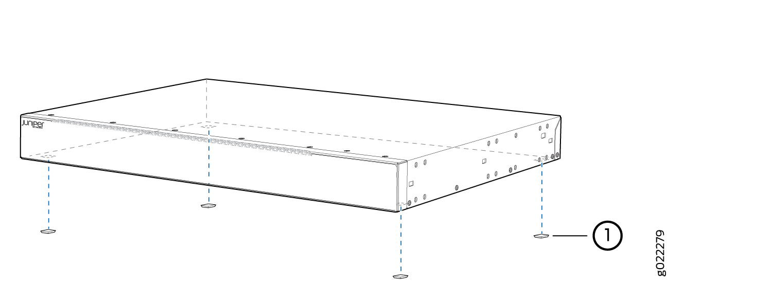
Turn the chassis right side up and place it on the desk or the level surface.
Ensure the router rests firmly on the desk or level surface.
After you finish mounting the router on a desk or level surface, see Connect the SSR440 Routers to Power.
Mount an SSR440 on a Two-Post Rack
Ensure that you have the following parts and tools available:
-
SSR400-RMK rack mount kit—separately orderable
-
Power adapter tray
-
Four cable ties
-
Four M4 screws
-
-
One AC power adapter for the SSR440 and SSR440-C models
-
Two AC power adapters for the SSR440-2AC and SSR440-C-2AC models
-
Phillips (+) screwdriver, number 2
If you are mounting multiple units on a rack, mount the units from the bottom to the top of the rack in decreasing order of weights. Therefore, you mount the heaviest unit right at the bottom and the lightest unit right at the top of the rack.
To mount an SSR440 Router on a two-post rack:
Remove the router, power adapter tray, and the AC power adapter from the shipping carton.
The power adapter tray will host the SSR440 Router and one or two AC power adapters.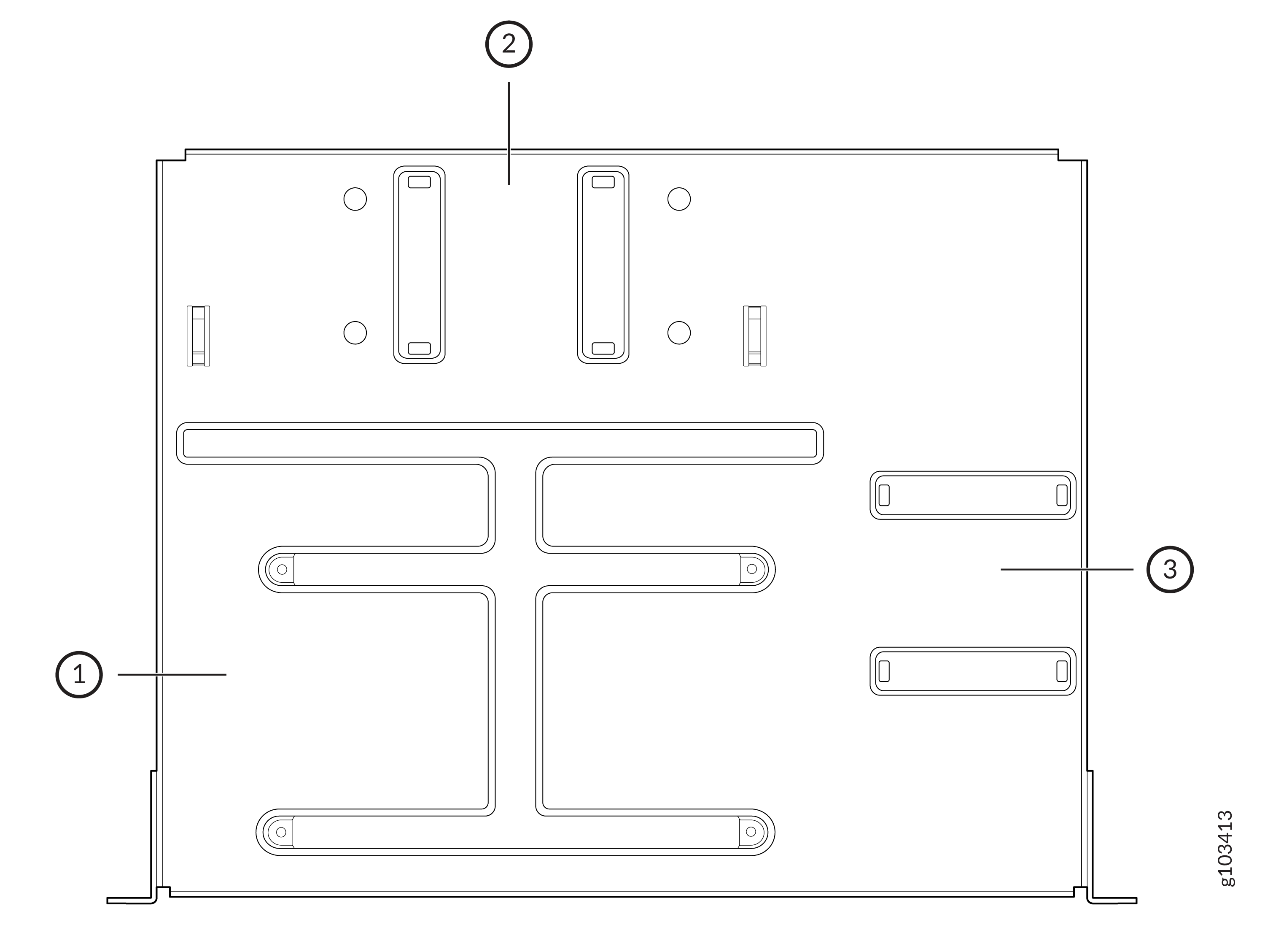
Callout
Component
1
SSR440 Chassis
2
Power adapter 1
3
Power adapter 2
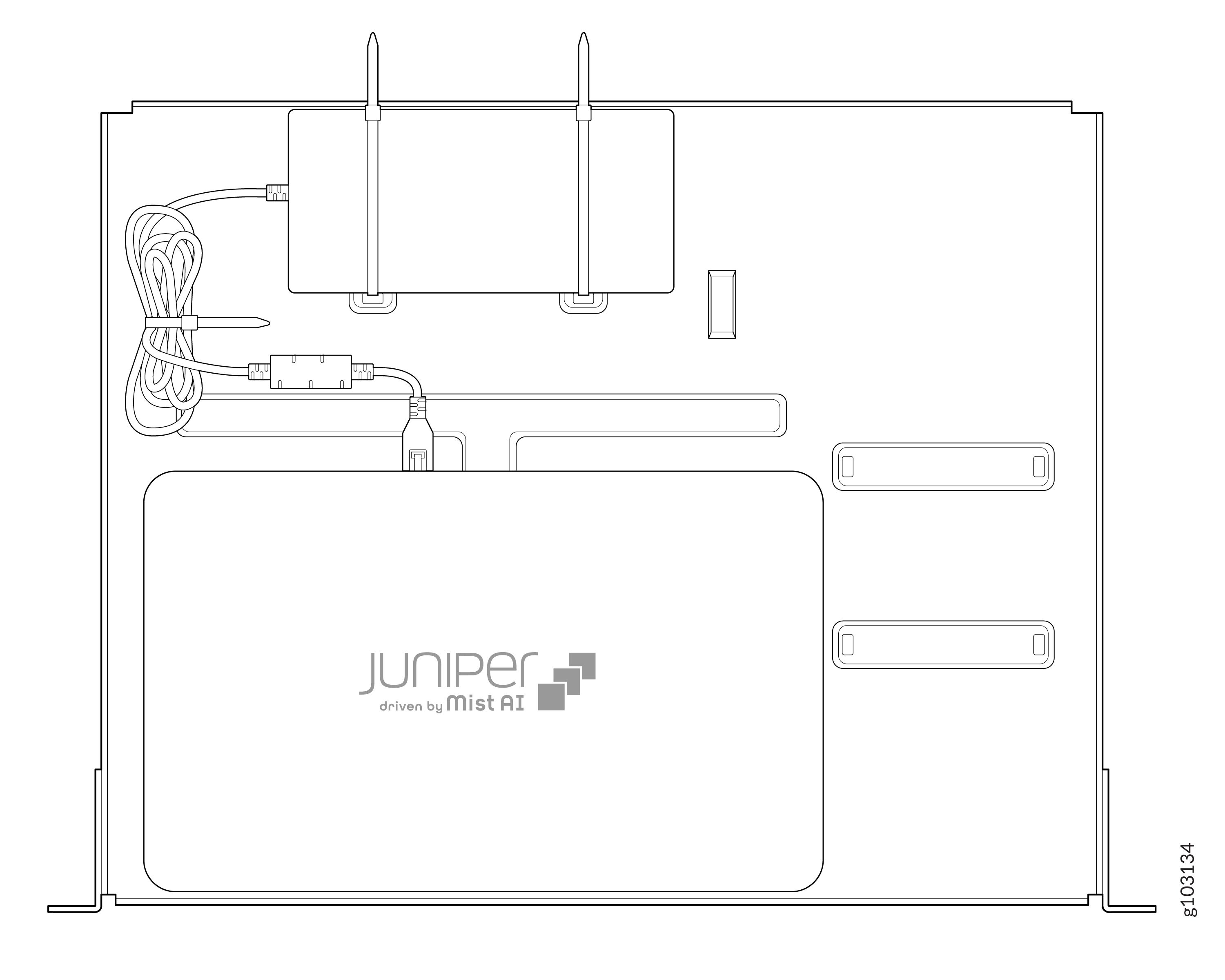
To install the power adapter on the tray:
Take a cable tie and insert the tailend of the cable tie through the two holes on the tray.
Repeat 2.a with the second cable tie.
Place the power adapter on the tray in between the cable ties.
Take the tailend of one cable tie, insert it through the square locking piece (other end of the cable tie) and pull the tie through the main head to set the length of excess material.
Repeat 2.d with the second cable tie.
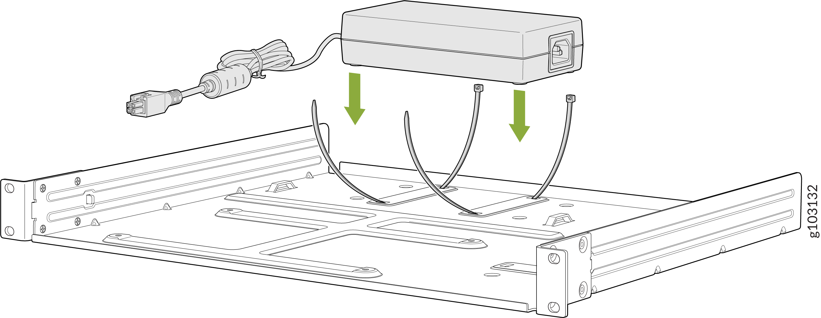
Repeat 2 to insert the second power adapter if your router is SSR440-2AC or SSR440-C-2AC.
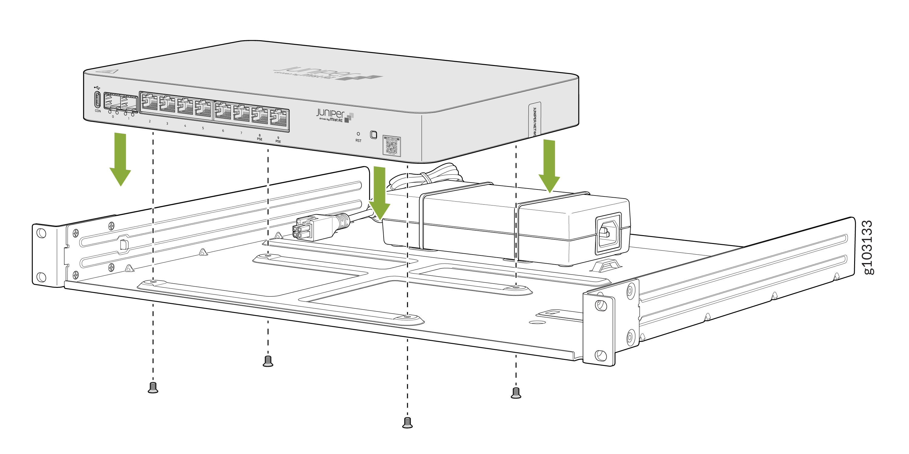
To install any one of the SSR440 chassis on the tray:
Have one person grasp the sides of the tray and hold it.
Have a second person position the chassis on the tray and align the bottom holes of the chassis with the four holes on the tray.
Install the four M4 screws into each of these four holes on the tray. Use the Phillips (+) screwdriver, number 2 to tighten the four screws and secure the chassis to the tray.
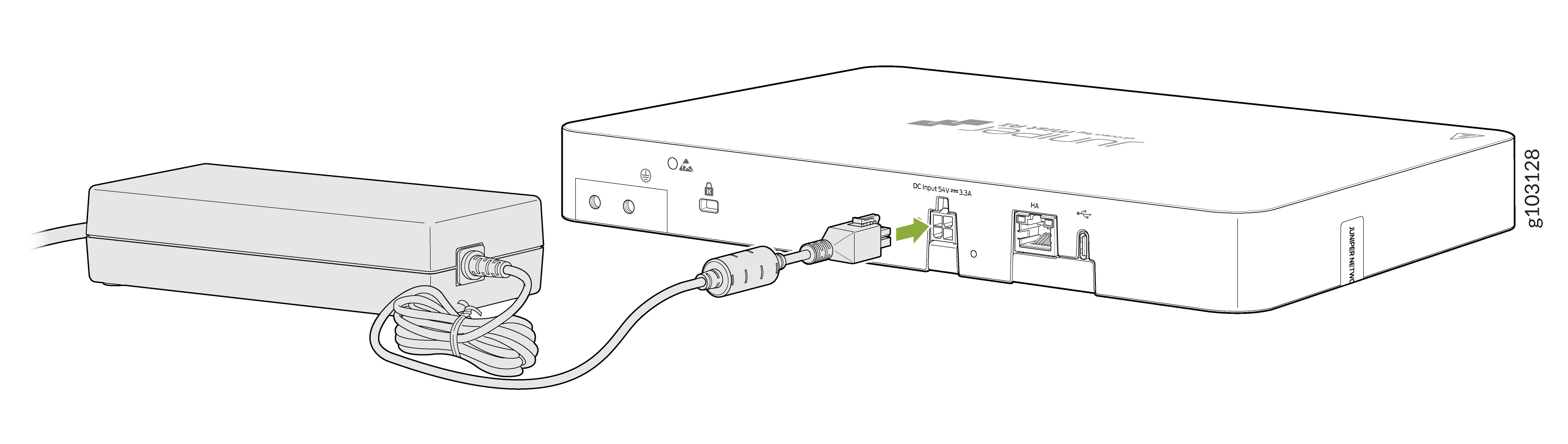
Plug the DC connector end of the power cable into the power connector on the back of the router.
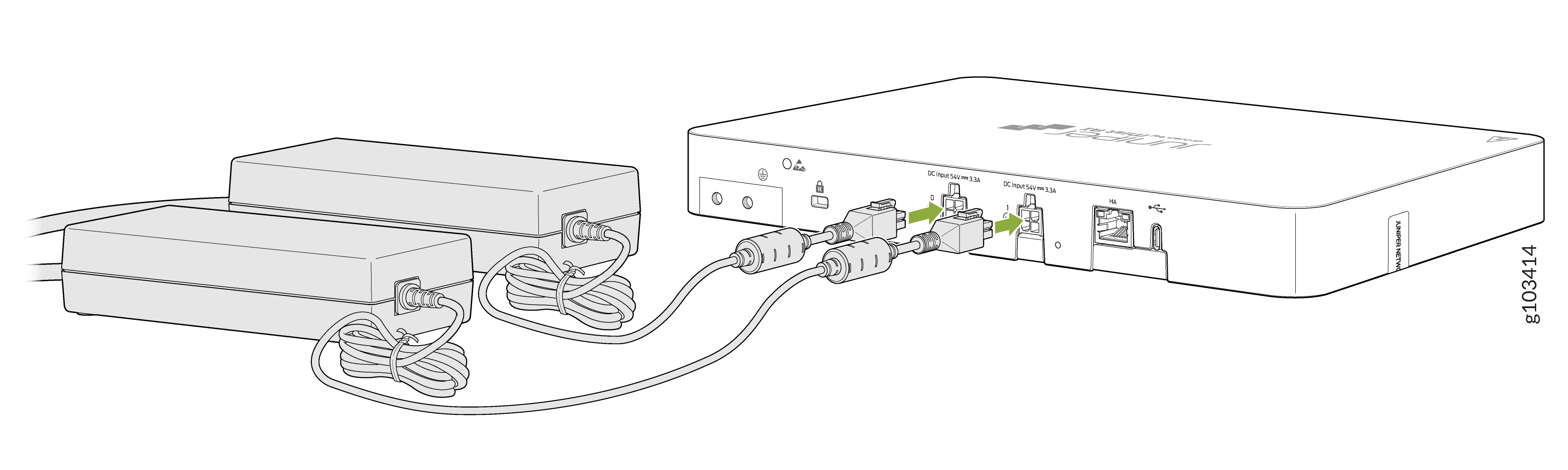
Repeat if you've installed the second power adapter.
Have one person grasp the sides of the tray, lift it, and position it in the rack.
Align the holes on the tray with the holes on the rack rails, making sure the router is level.
Have a second person secure the router to the rack by using four mounting screws (not provided). Use the Phillips (+) screwdriver, number 2 to tighten the four screws and secure the power adapter tray to the rack. Tighten the screws with a torque of 18 Nm.
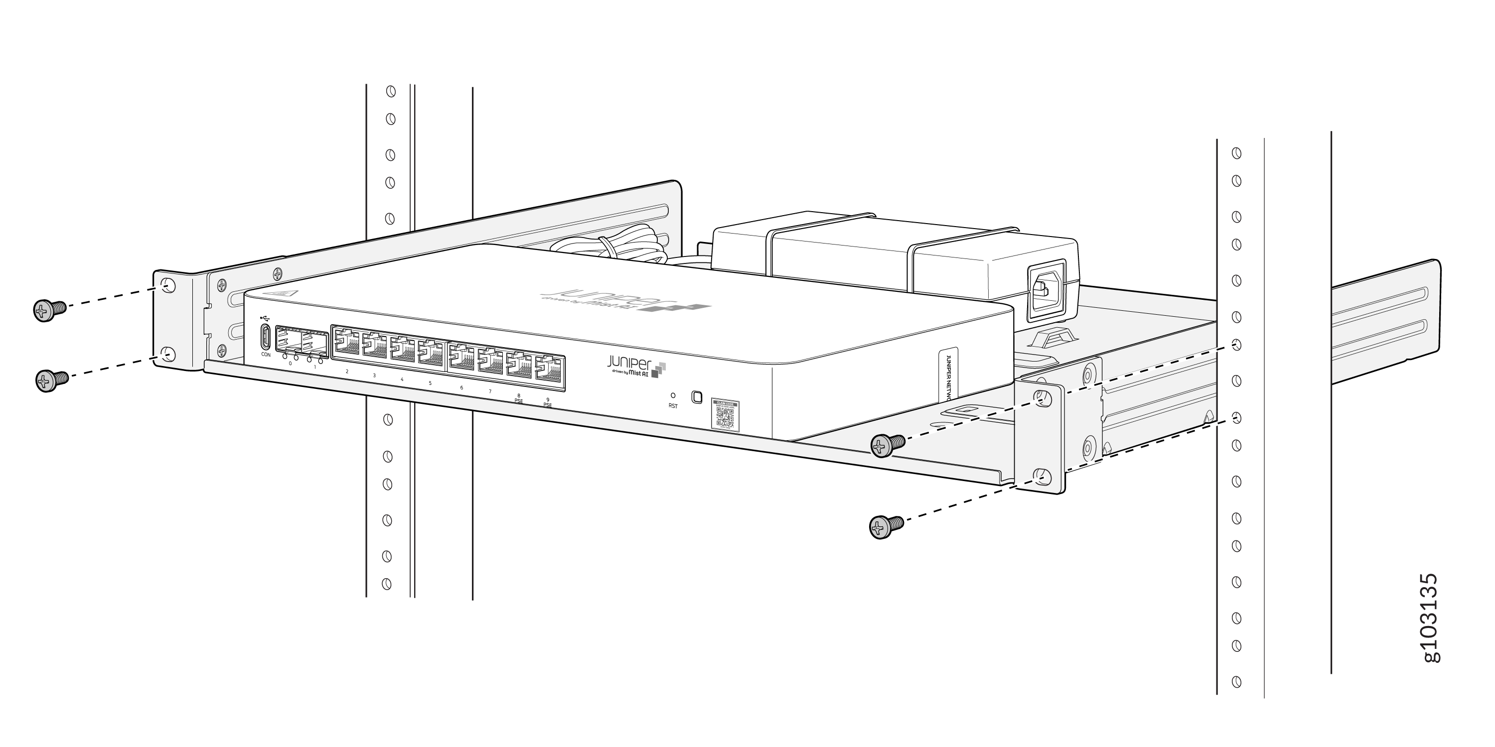
Ensure that the router is level by verifying that all the screws on one side of the rack are aligned with the screws on the other side.
Install Antennas and SIM Card on the SSR440 LTE Models
The SSR440 LTE variants: SSR440-C and SSR440-C-2AC have an integrated modem and operate over 5G networks. SSR440-C and SSR440-C-2AC support:
-
Multi-Band Swivel Mount Dipole antennas (SSR400-5G-ANT) (here on are referred to as antenna)
-
SSR400-5G-EXT—Double-port antenna holder with antenna extension RF cable (separately orderable)
-
SIM card
Install Antennas
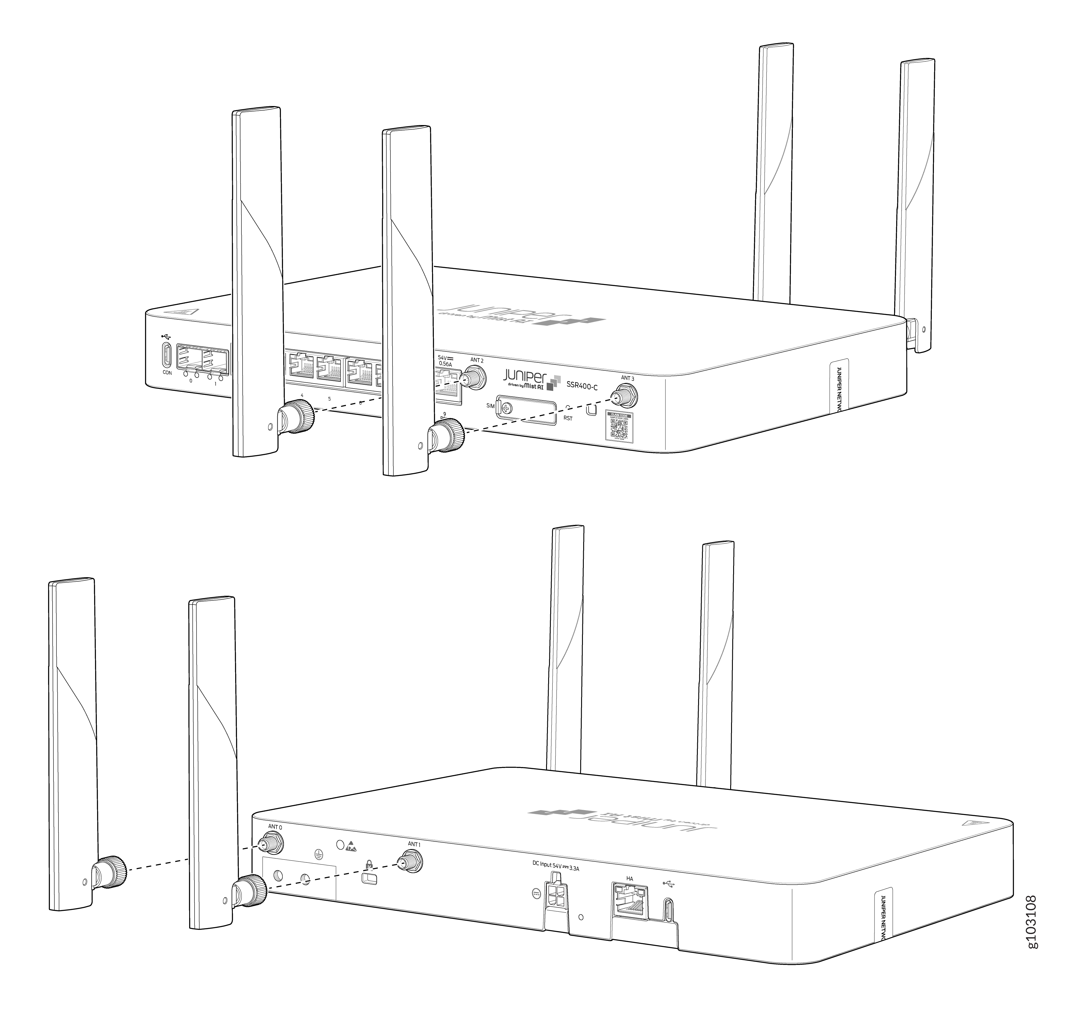
To install the antennas directly on the router:
Remove the dust caps from the SubMiniature version A (SMA) connectors on the router front and rear panels.
Attach the antennas to the SMA connectors on the device and tighten them firmly by hand.
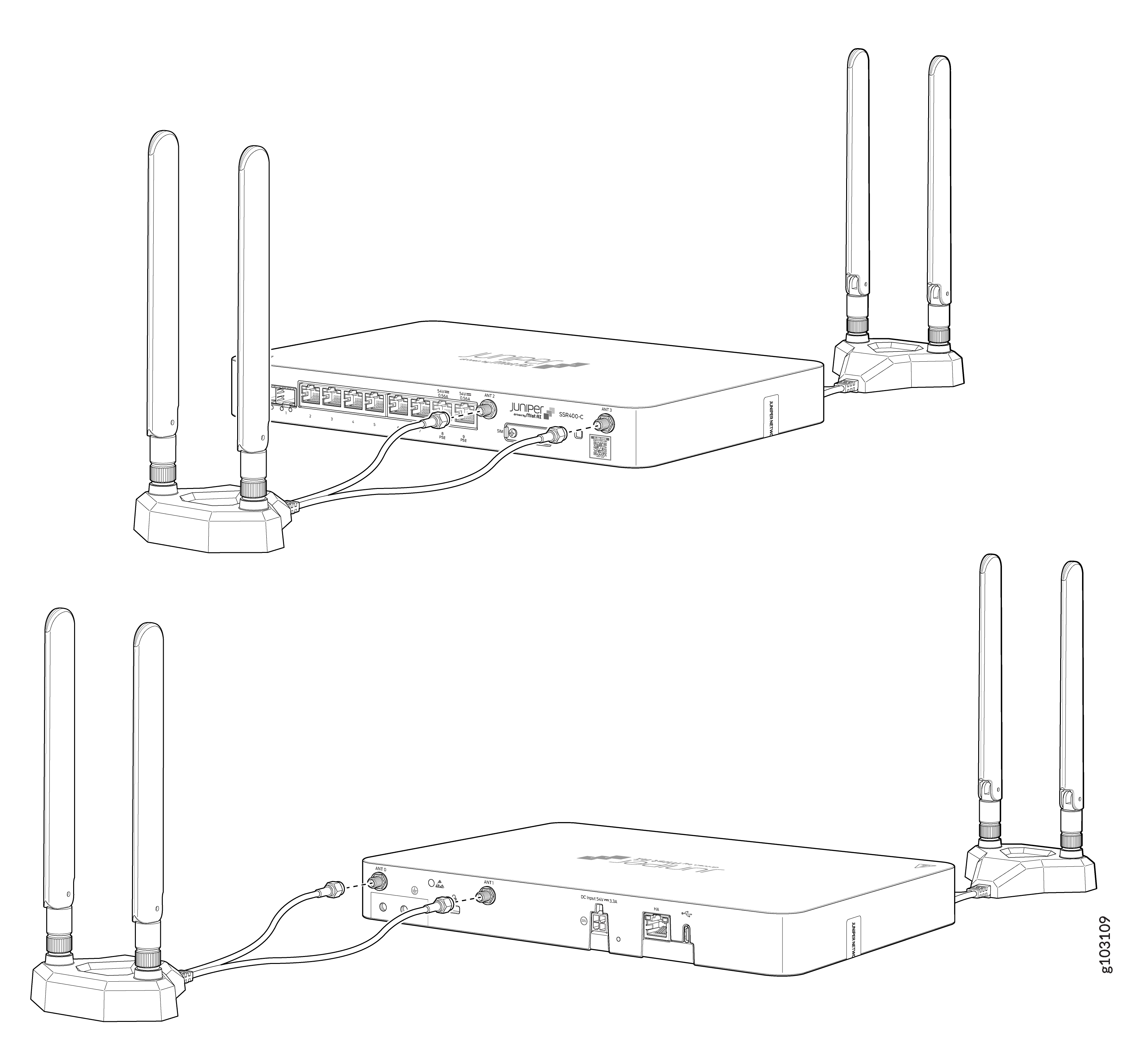
To install the antennas using the separately orderable double-port antenna holder with the antenna extension RF cable:
Remove the dust caps from the SubMiniature version A (SMA) connectors from the router front and rear panels.
Attach the antennas to the antenna holders. Connect the RF cables from each antenna holder to the SMA connectors on the router and tighten them firmly by hand.
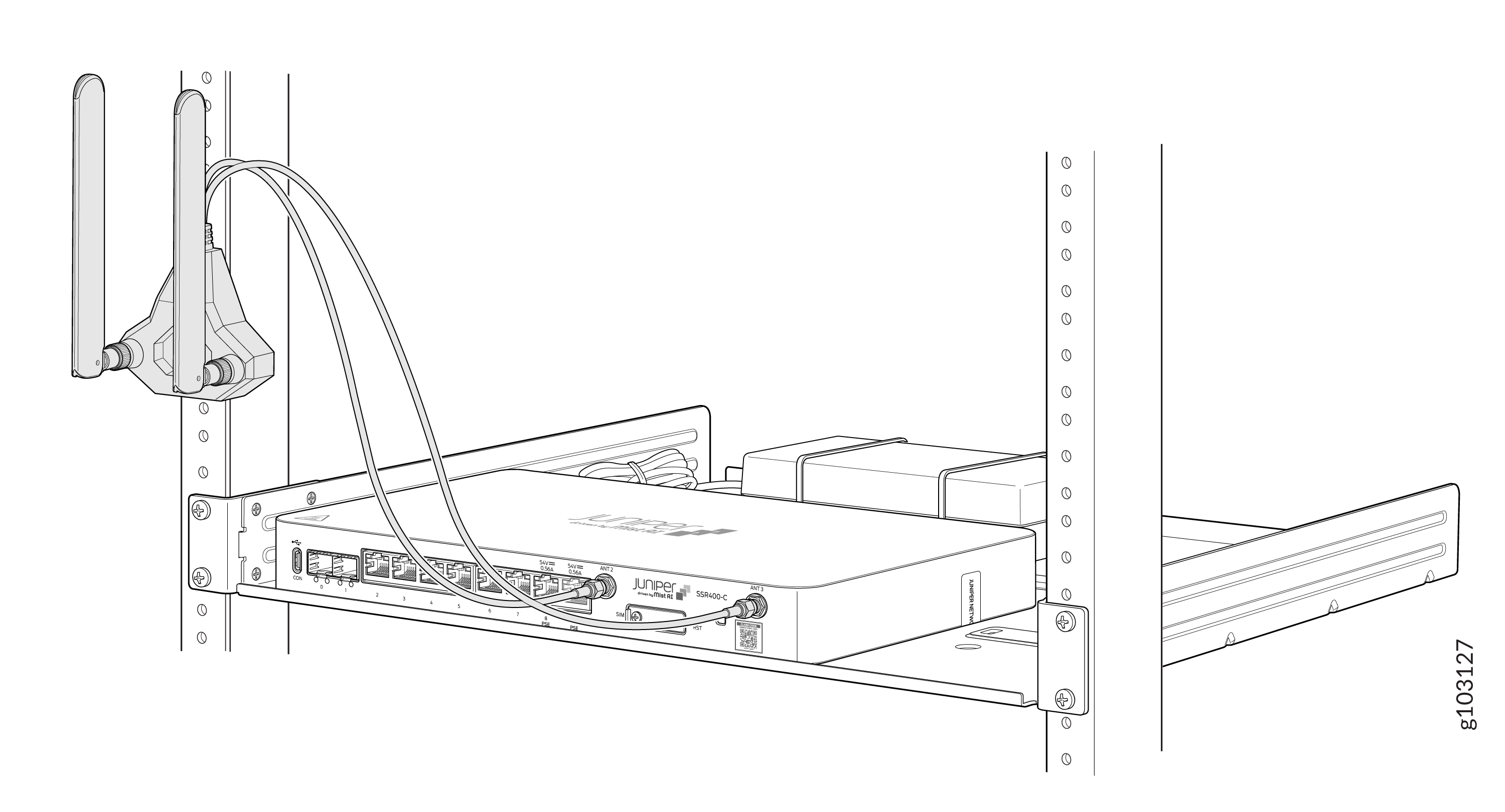
The antenna holder is magnetic and can be attached to the rack directly if the rack is metallic.
Insert the SIM Card
The SSR440 LTE variants SSR440-C and SSR440-C-2AC support SIM card. To insert a SIM card:
Using a Phillips (+) screwdriver, number 2, loosen the M2.5 screw on the SIM card slot cover and rotate the cover 900 to the right.
Ensure correct orientation of the SIM card─the chip side (Gold finger) must face down into the slot and the edge cut must face toward the chassis.
Position the SIM card horizontally in the slot.
Insert the SIM card in the slot and push it in until the latch mechanism locks it in place and you hear a click sound.
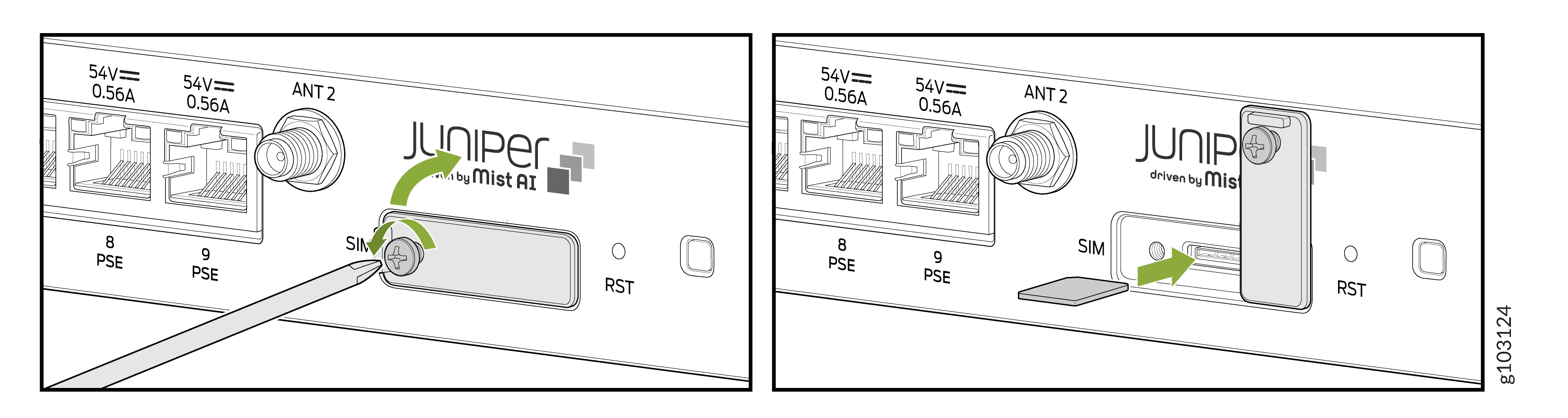
Roll back the SIM card slot cover and tighten its screw with a torque of 1.8 Nm.