
ON THIS PAGE
SSR440 Chassis
Learn about the components in the SSR440 chassis.
Each SSR440 model chassis is a rigid sheet-metal structure that houses all device components.
SSR440 Specifications
| Specification | SSR440 Models (SSR440, SSR440-2AC, SSR440-C, and SSR440-C-2AC) |
|---|---|
|
Height |
1.3 in. (3.3 cm) |
|
Width |
11.81 in. (29.9 cm) |
|
Depth |
7.52 in. (19.1 cm) |
|
Weight |
|
| Specification | Value |
|---|---|
|
Operating altitude |
6561.68 ft (2000 m) |
|
Operating temperature |
|
|
Storage temperature |
-40 °F to 158 °F (-40 °C to 70 °C) |
|
Relative humidity (operating) (noncondensing) |
10% to 90% |
|
Relative humidity (nonoperating) (noncondensing) |
5% to 95% |
|
Seismic tolerance |
Zone 4 |
SSR440 Models
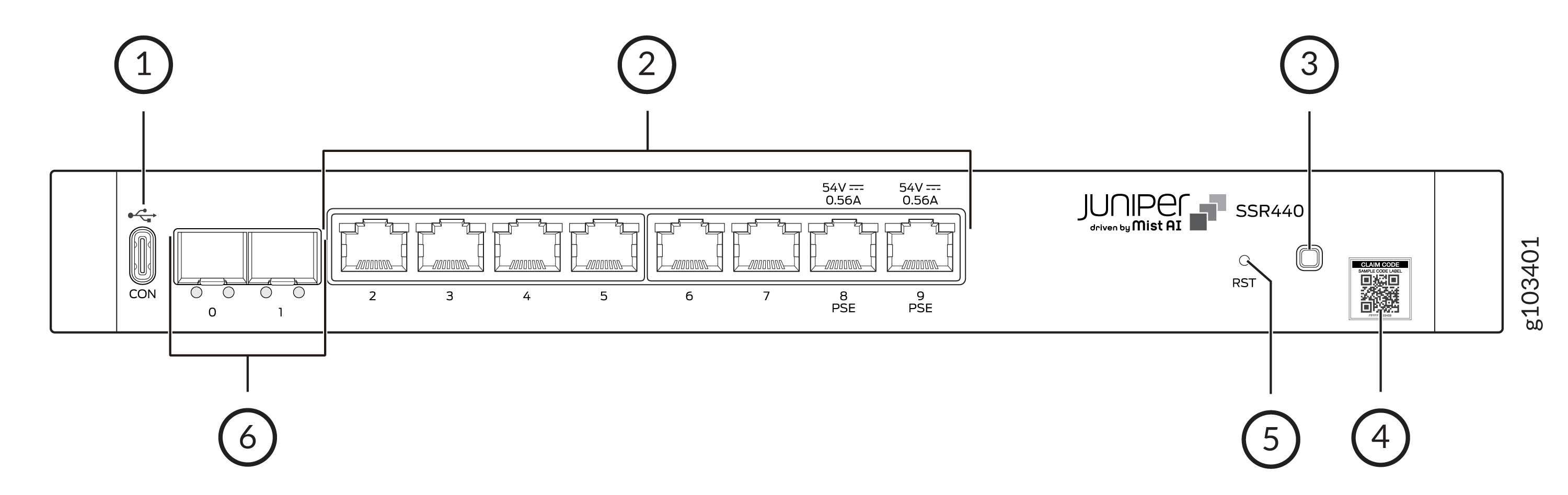
| Callout | Item |
|---|---|
|
1 |
Console port—USB Type C |
|
2 |
Eight 10/100/1000GbE Base-T RJ-45 network ports Ports 8 and 9 support PoE PSE (30 W each) |
|
3 |
Multicolor system LED |
|
4 |
QR code label |
|
5 |
RESET button |
|
6 |
Two 1GbE SFP ports |
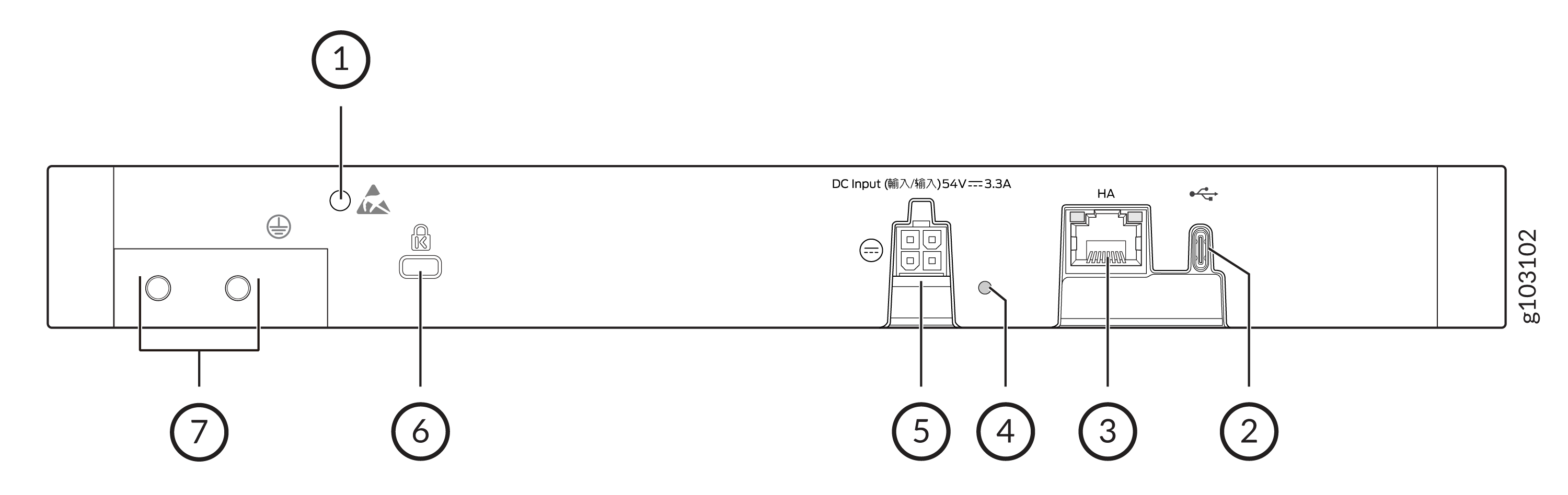
| Callout | Item |
|---|---|
|
1 |
ESD point |
|
2 |
USB 2.0 Type C port that accepts a USB storage device. |
|
3 |
1GbE RJ-45 HA port |
|
4 |
Power supply adapter (PSA) LED |
|
5 |
PSA point |
|
6 |
Security slot to lock and secure the chassis |
|
7 |
Ground terminal |
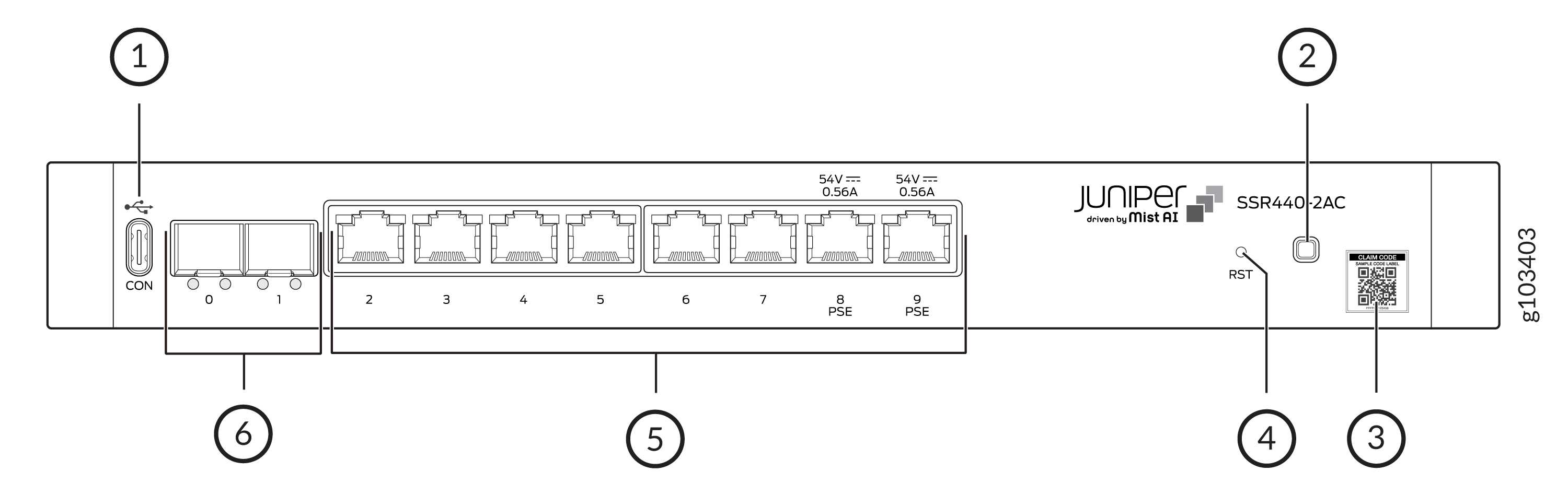
| Callout | Item |
|---|---|
|
1 |
Console port—USB Type C |
|
2 |
Multicolor system LED |
|
3 |
QR code label |
|
4 |
RESET button |
|
5 |
Eight 10/100/1000GbE Base-T RJ-45 network ports Ports 8 and 9 support PoE PSE (30 W each) |
|
6 |
Two 1GbE SFP ports |
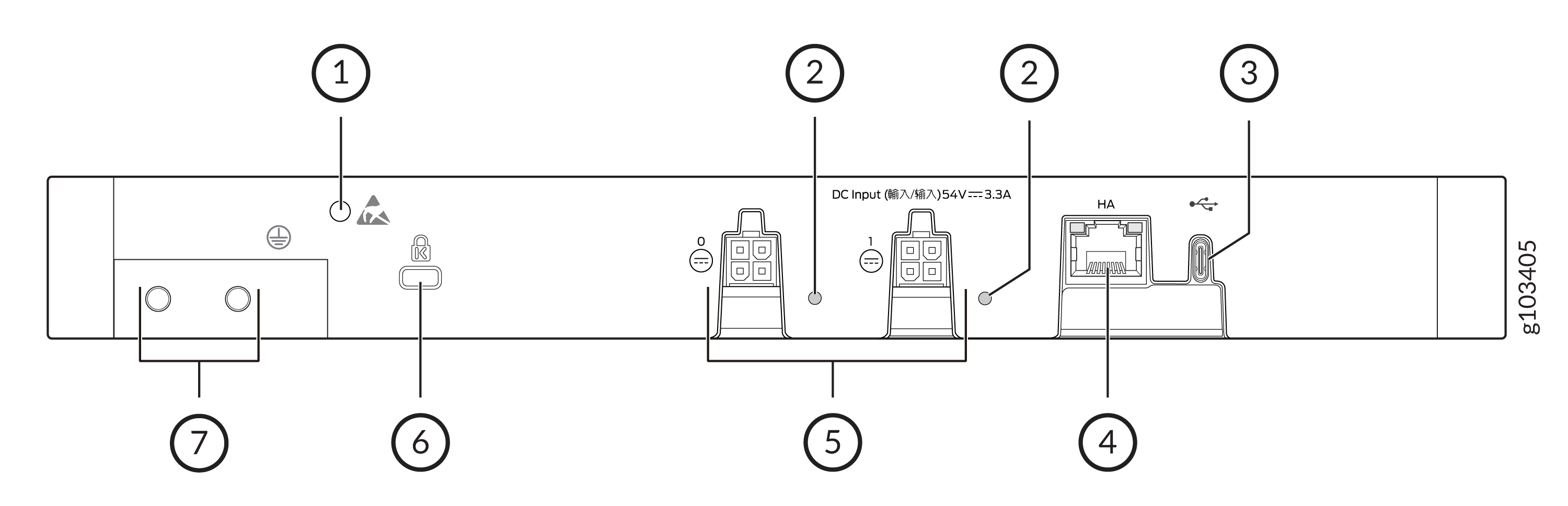
| Callout | Item |
|---|---|
|
1 |
ESD point |
|
2 |
Power supply adapter (PSA) LED |
|
3 |
USB 2.0 Type C port that accepts a USB storage device. |
|
4 |
1GbE RJ-45 HA port |
|
5 |
Two PSA points |
|
6 |
Security slot to lock and secure the chassis |
|
7 |
Ground terminal |
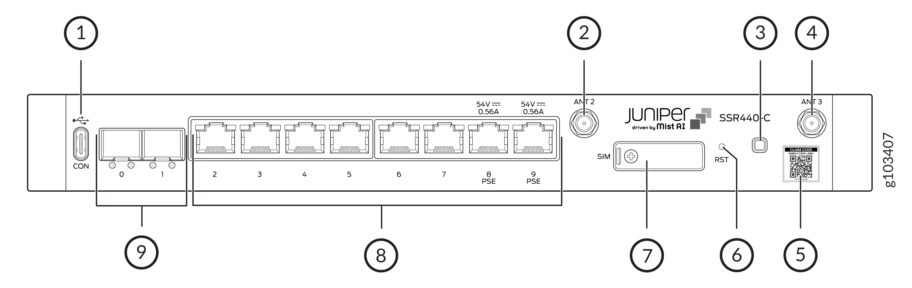
| Callout | Item |
|---|---|
|
1 |
Console port—USB Type C |
|
2 |
SubMiniature version A (SMA) antenna connector |
|
3 |
Multicolor system LED |
|
4 |
SMA antenna connector |
|
5 |
QR code label |
|
6 |
RESET button |
|
7 |
SIM slot |
|
8 |
Eight 10/100/1000GbE Base-T RJ-45 network ports Ports 8 and 9 support PoE PSE (30 W each) |
|
9 |
Two 1GbE SFP ports |
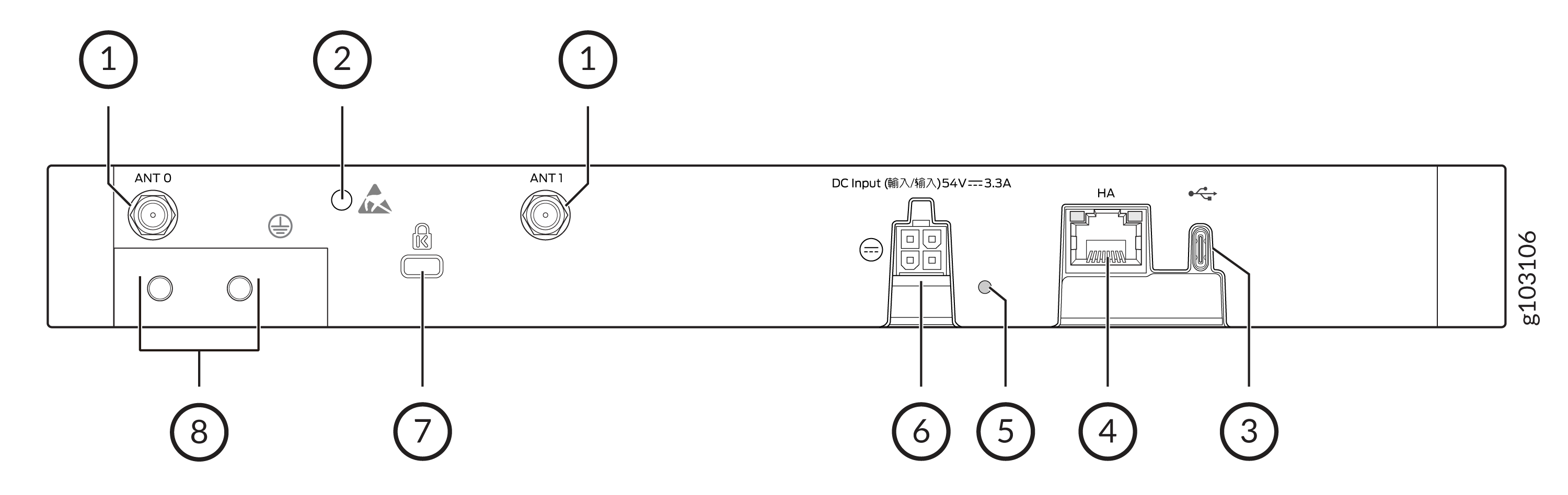
| Callout | Item |
|---|---|
|
1 |
SubMiniature version A (SMA) antenna connectors |
|
2 |
ESD point |
|
3 |
USB 2.0 Type C port that accepts a USB storage device. |
|
4 |
1GbE RJ-45 HA port |
|
5 |
Power supply adapter (PSA) LED |
|
6 |
PSA point |
|
7 |
Security slot to lock and secure the chassis |
|
8 |
Ground terminal |
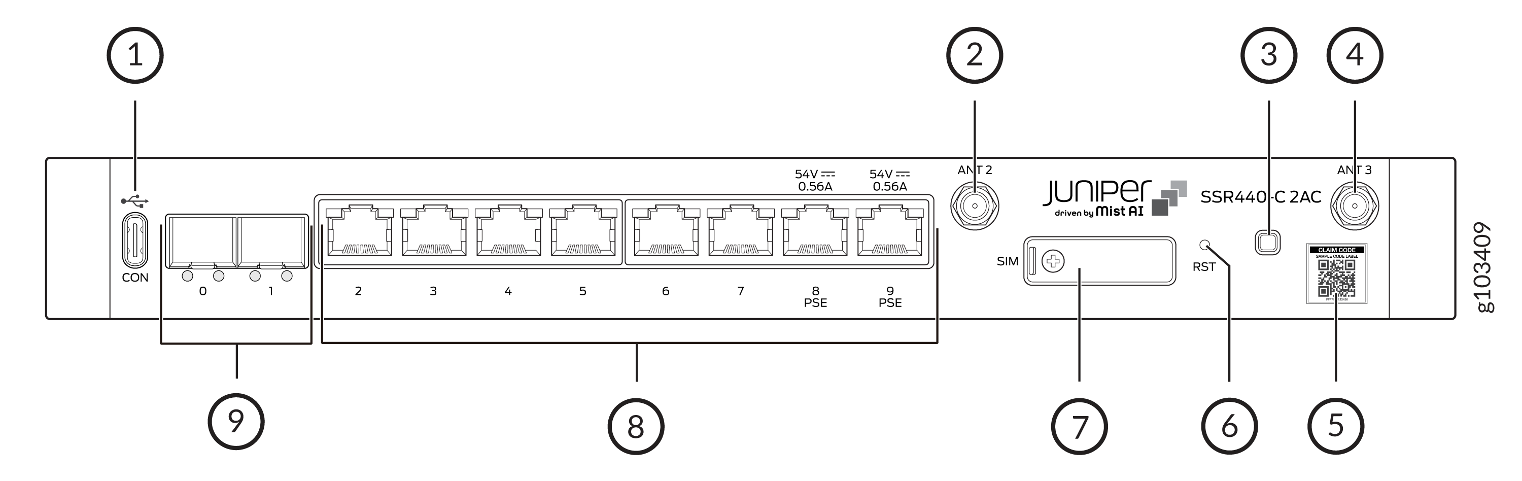
| Callout | Item |
|---|---|
|
1 |
Console port—USB Type C |
|
2 |
SubMiniature version A (SMA) antenna connector |
|
3 |
Multicolor system LED |
|
4 |
SMA antenna connector |
|
5 |
QR code label |
|
6 |
RESET button |
|
7 |
SIM slot |
|
8 |
Eight 10/100/1000GbE Base-T RJ-45 network ports Ports 8 and 9 support PoE PSE (30 W each) |
|
9 |
Two 1GbE SFP ports |
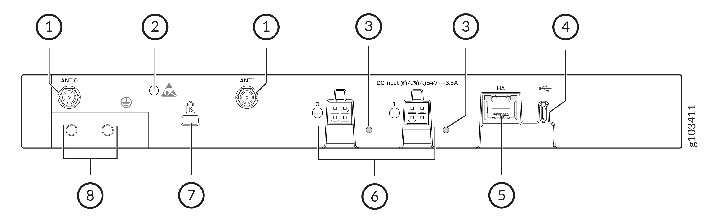
| Callout | Item |
|---|---|
|
1 |
SubMiniature version A (SMA) antenna connectors |
|
2 |
ESD point |
|
3 |
Power supply adapter (PSA) LED |
|
4 |
USB 2.0 Type C port that accepts a USB storage device. |
|
5 |
1GbE RJ-45 HA port |
|
6 |
Two PSA points |
|
7 |
Security slot to lock and secure the chassis |
|
8 |
Ground terminal |