SSR1500 Chassis
Front Panel of an SSR1500
Figure 1 shows the front panel of an SSR1500. The SSR1500 comes with a claim code (QR code) that you can use to onboard the SSR1500 to Juniper Mist.
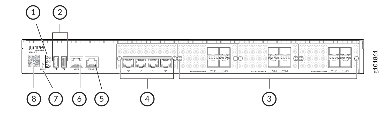
1 — Chassis LEDs | 5 — RJ-45 Console port |
2 — USB 3.0 ports Note:
Do not use SanDisk Ultra Fit USB 3.1 SDCZ430 32GB/64GB/128GB and SanDisk Ultra USB 3.0 SDCZ48 32 GB USBs. | 6 — 1 GbE management port (for Mist operations) |
3 — 1/10/25 GbE SFP28 ports (2/0 through 4/3) | 7 — RESET button |
4 — 1 GbE Ethernet ports (1/0 through 1/3) | 8 — Claim code |
Rear Panel of an SSR1500
Figure 2 shows the rear panel of an SSR1500.
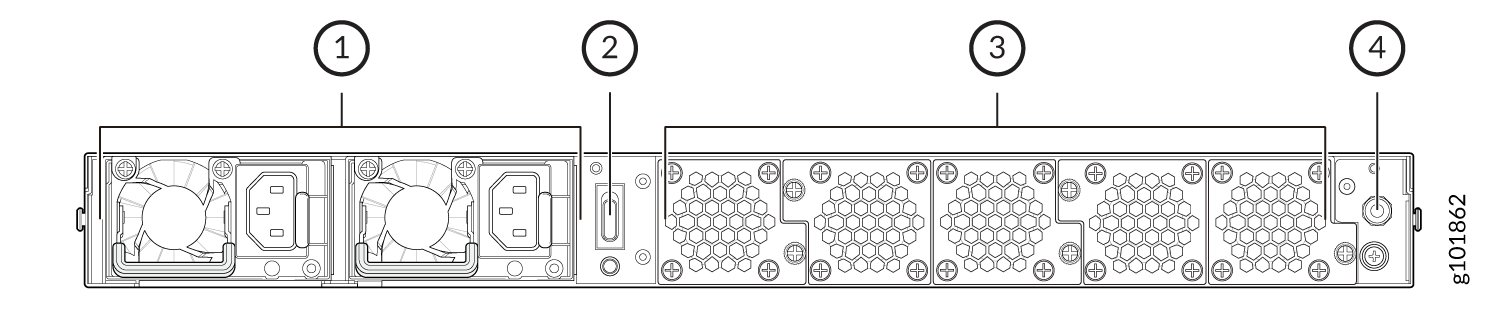
1 — AC power supply units | 3 — Fans |
2 — Power switch | 4 — Earth grounding |
Chassis Physical Specifications for SSR1500
Table 1 summarizes the physical specifications of SSR1500.
| Model | Height | Width | Depth | Weight |
|---|---|---|---|---|
| SSR1500 | 44 mm | 438 mm | 610 mm | 22 kg (48.51 lbs.) |
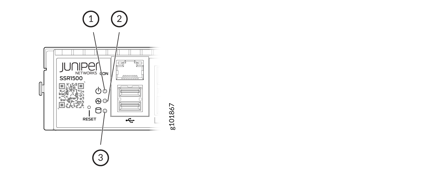
Chassis Status LEDs
Figure 3 shows the LEDs on the front panel, and Table 2 describes the LEDs.
| Callout | LED | Description |
|---|---|---|
| 1 | Power |
|
| 2 | Status |
|
| 3 | SSD |
|
Network Port LEDs
Each network port uses two LEDs to indicate the link activity and speed. Figure 4 shows the location of the LEDs on the Ethernet and SFP28 ports.
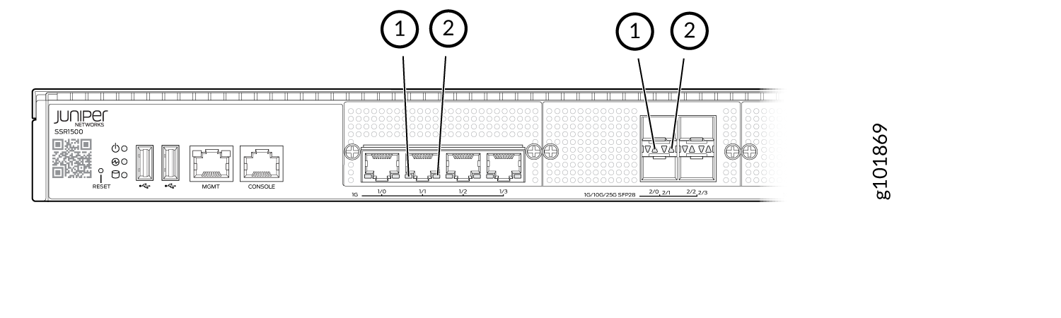
Table 3 describes the LEDs on the Ethernet ports.
| Callout | LED | Description |
|---|---|---|
| 1 | Link Activity (LED on the left) |
|
| 2 | Speed (LED on the right) |
|
Table 4 describes the LEDs on the SFP28 ports.
| Callout | LED | Description |
|---|---|---|
| 1 | Link Activity (LED on the left) |
|
| 2 | Speed (LED on the right) |
|
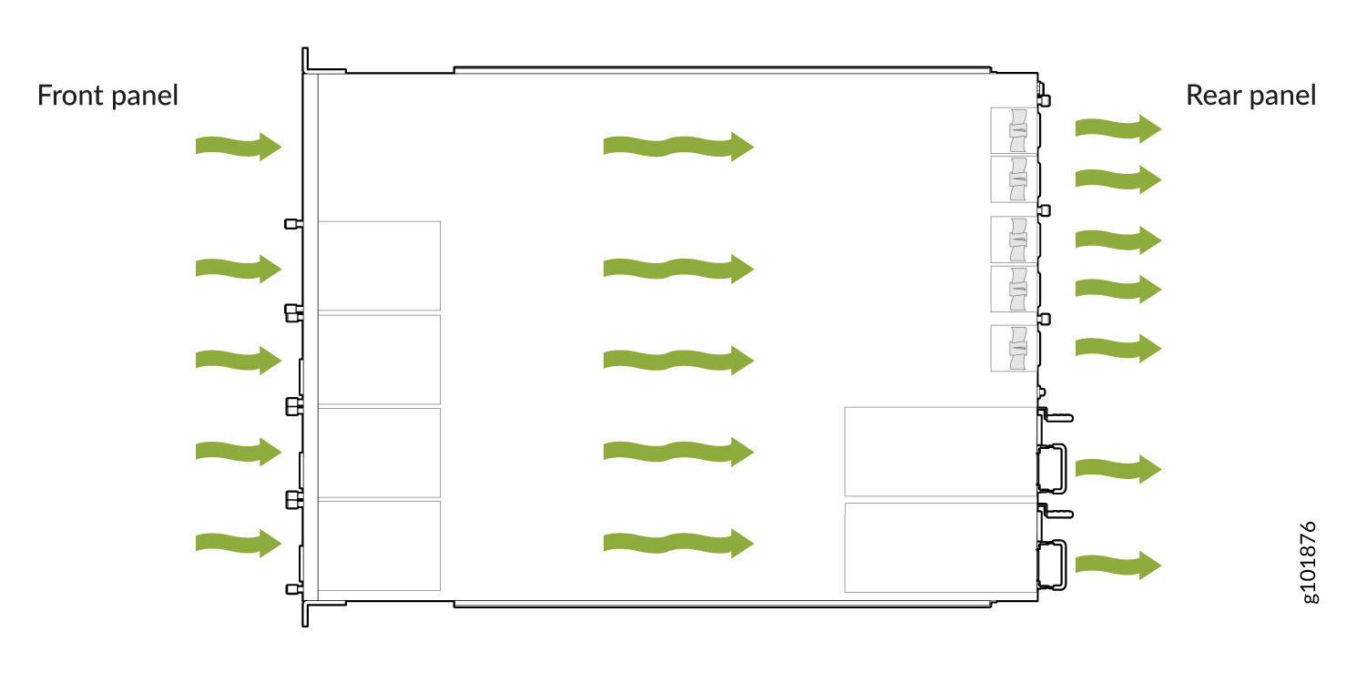
Cooling System
The cooling system of the SSR1500 consists of five fans, which are hot-insertable and hot-removable field-replaceable units (FRUs). You can remove and replace them without powering off the appliance or disrupting appliance functions.
The SSR1500 appliances have front-to-back airflow. The air is pulled in through the front of the chassis toward the fan modules, from where it is exhausted out of the chassis.
Power System
The SSR1500 appliance ships with two AC power supply units (1+1 redundancy) preinstalled. Each power supply unit is a hot-removable and hot-insertable field-replaceable unit (FRU) when the second power supply is installed and running. You can remove and replace either one of them without powering off the appliance or disrupting the appliance functions.
If both power supply units are installed, and if only one power supply unit is connected to the power source, the appliance raises an alarm.
Each power supply has its own fan and is cooled by its own internal cooling system.
Table 5 lists the power specifications for the SSR1500 appliance.
| Model | AC Input Voltage (Operating Range) | AC Input Line Frequency | AC Input Current Rating | Maximum Power Consumption | Power Supply Type |
|---|---|---|---|---|---|
| SSR1500 | 100–240 VAC | 50–60 Hz | 3–5 A | 550 W | External, hot swappable |
AC Power Cord Specifications for SSR1500
We ship detachable region-specific AC power cords with the chassis. The coupler is type C13 as described by International Electrotechnical Commission (IEC) standard 60320. The plug end of the power cord fits into the power source outlet that is standard for your geographical location.
Table 6 lists the AC power cords specifications provided for the power supplies for each country or region.
|
Country/Region |
Electrical Specifications |
Plug Standards |
Juniper Model Number |
Graphic |
|---|---|---|---|---|
|
Argentina |
250 VAC, 10 A, 50 Hz |
IRAM 2073 Type RA/3 |
CBL-EX-PWR-C13-AR |
No graphic available |
|
Australia |
250 VAC, 10 A, 50 Hz |
AS/NZS 3112 Type SAA/3 |
CBL-EX-PWR-C13-AU |
|
|
Brazil |
250 VAC, 10 A, 50 Hz |
NBR 14136 Type BR/3 |
CBL-EX-PWR-C13-BR |
No graphic available |
|
China |
250 VAC, 10 A, 50 Hz |
GB 1002-1996 Type PRC/3 |
CBL-EX-PWR-C13-CH |
|
|
Europe (except Italy, Switzerland, and United Kingdom) |
250 VAC, 10 A, 50 Hz |
CEE (7) VII Type VIIG |
CBL-EX-PWR-C13-EU |
|
|
India |
250 VAC, 10 A, 50 Hz |
IS 1293 Type IND/3 |
CBL-EX-PWR-C13-IN |
No graphic available |
|
Israel |
250 VAC, 10 A, 50 Hz |
SI 32/1971 Type IL/3G |
CBL-EX-PWR-C13-IL |
|
|
Italy |
250 VAC, 10 A, 50 Hz |
CEI 23-16 Type I/3G |
CBL-EX-PWR-C13-IT |
|
|
Japan |
125 VAC, 12 A, 50 Hz or 60 Hz |
JIS 8303 |
CBL-EX-PWR-C13-JP |
|
|
Korea |
250 VAC, 10 A, 50 Hz or 60 Hz |
CEE (7) VII Type VIIGK |
CBL-EX-PWR-C13-KR |
|
|
North America |
125 VAC, 13 A, 60 Hz |
NEMA 5-15 Type N5-15 |
CBL-EX-PWR-C13-US |
|
|
South Africa |
250 VAC, 10 A, 50 Hz |
SABS 164/1:1992 Type ZA/3 |
CBL-EX-PWR-C13-SA |
|
|
Switzerland |
250 VAC, 10 A, 50 Hz |
SEV 6534-2 Type 12G |
CBL-EX-PWR-C13-SZ |
No graphic available |
|
United Kingdom |
250 VAC, 10 A, 50 Hz |
BS 1363/A Type BS89/13 |
CBL-EX-PWR-C13-UK |
|