SRX5800 Firewall Cooling System
The cooling system consists of the following components:
-
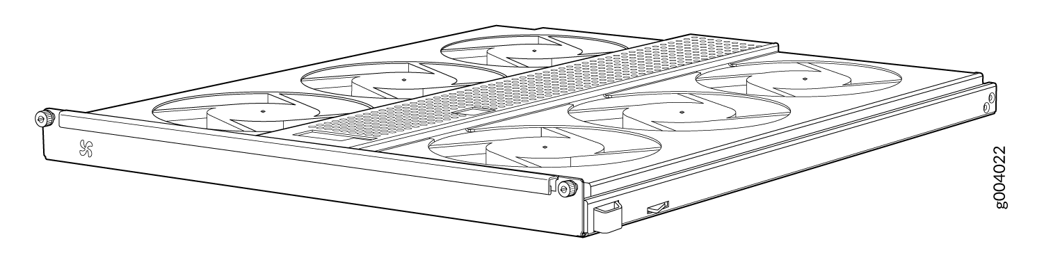
Upper fan tray
-
Bottom fan tray
-
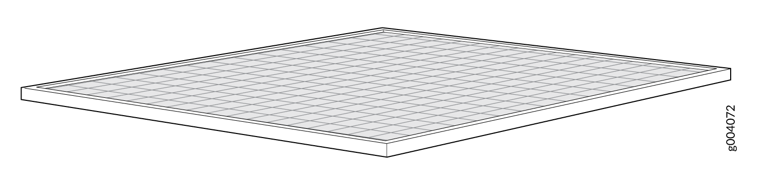
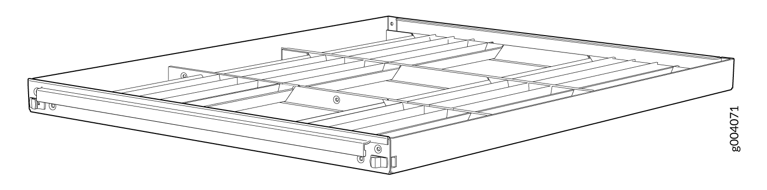
Air filter tray and air filter
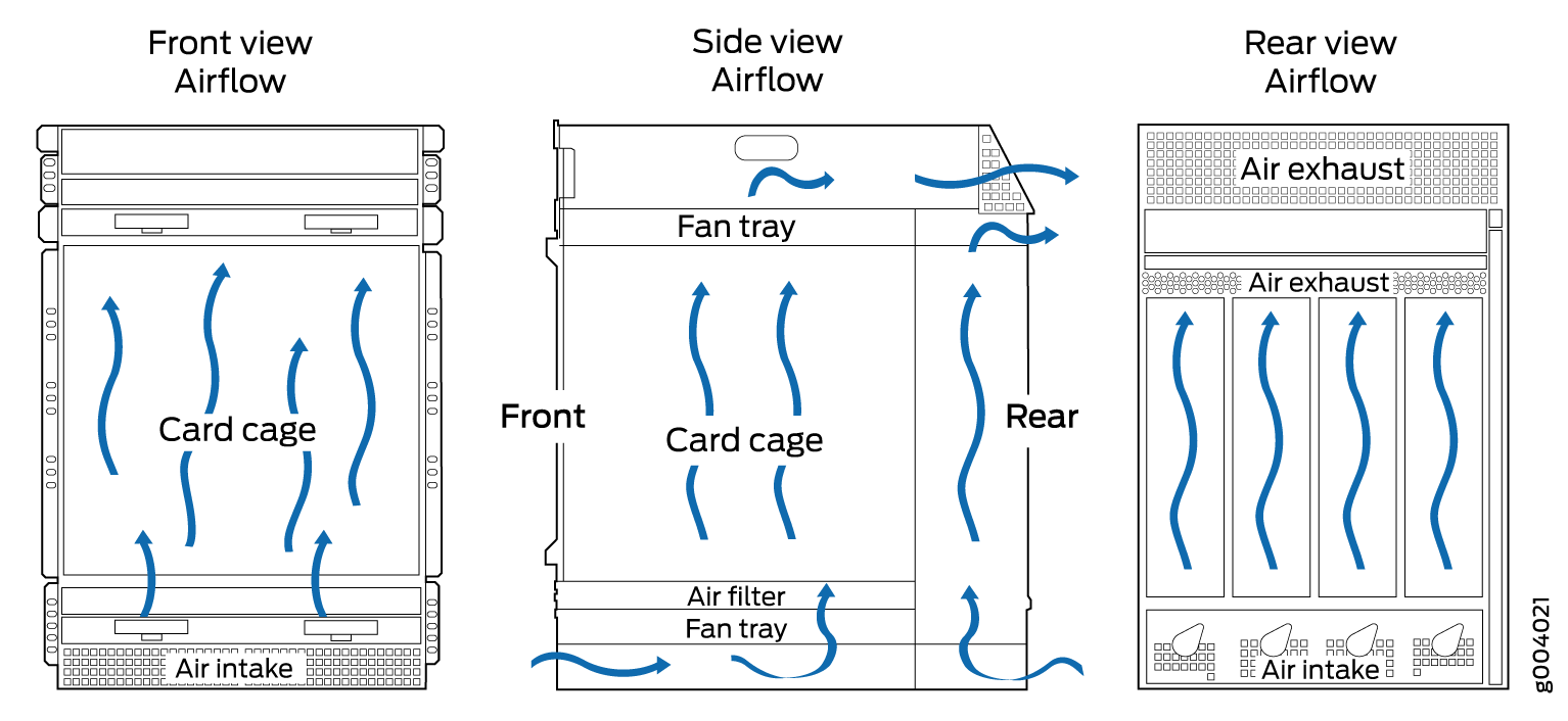
The cooling system components work together to keep all firewall components within the acceptable temperature range (see Figure 1, Figure 2, Figure 3, Figure 4, and Figure 5). The firewall has two fan trays located in the front of the device that install horizontally above and below the card cage.
In the Junos OS command-line interface (CLI):
-
The
show chassis hardwarecommand output displays the fan trays asFan Tray 0for the upper fan tray andFan Tray 1for the bottom fan tray. -
The
show chassis environmentcommand output displays the fan trays asUpper Fan TrayandBottom Fan Tray.
Two different types of fan trays are available:
-
The standard capacity fan tray has six fans that operate at 728 cubic feet per minute (CFM) at full speed and is adequate for firewalls in which standard-capacity power supplies are installed.
-
The high-capacity fan tray has 12 fans that operate at 976 cubic feet per minute (CFM) at full speed and is required when high-capacity power supplies are installed. When high-capacity fan trays are installed, you must also install the high-capacity air filter tray.
The fan trays are interchangeable and are hot-insertable and hot-removable.
The host subsystem monitors the temperature of the device components. When the device is operating normally, the fans function at lower than full speed. If a fan fails or the ambient temperature rises above a threshold, the speed of the remaining fans is automatically adjusted to keep the temperature within the acceptable range. If the ambient maximum temperature specification is exceeded and the system cannot be adequately cooled, the Routing Engine shuts down the system by disabling output power from each PEM.
There is a single air intake in the front of the firewall. Air is pushed up through an air filter, through the card cage, and then through the upper fan tray where it combines in a common exhaust plenum and is exhausted out the upper rear of the system.