SRX5400 Site Guidelines and Requirements
SRX5400 Firewall Environmental Specifications
Table 1 specifies the environmental specifications required for normal firewall operation. In addition, the site should be as dust-free as possible.
Description |
Value |
|---|---|
Altitude |
No performance degradation to 10,000 ft (3048 m) |
Relative humidity |
Normal operation ensured in relative humidity range of 5% to 90%, noncondensing |
Temperature |
Normal operation ensured in temperature range of 32°F (0°C) to 104°F (40°C) Nonoperating storage temperature in shipping container: –40°F (–40°C) to 158°F (70°C) |
Seismic |
Designed to meet Telcordia Technologies Zone 4 earthquake requirements |
Maximum thermal output |
AC power: 8065 BTU/hour (2365 W) DC power: 7325 BTU/hour (2148 W) |
Install the firewall only in restricted areas, such as dedicated equipment rooms and equipment closets, in accordance with Articles 110-16, 110-17, and 110-18 of the National Electrical Code, ANSI/NFPA 70.
General Site Guidelines
Efficient device operation requires proper site planning. For the device to operate properly, you must ensure maintenance and proper layout of the equipment, rack or cabinet, and wiring closet.
To plan and create an acceptable operating environment for your device and prevent environmentally caused equipment failures:
Keep the area around the chassis free from dust and conductive material, such as metal flakes.
Follow the prescribed airflow guidelines to ensure that the cooling system functions properly. Ensure that the exhaust from other equipment does not blow into the intake vents of the device.
Follow the prescribed electrostatic discharge (ESD) prevention procedures to prevent damaging the equipment. Static discharge can cause components to fail completely or intermittently over time.
Install the device in a secure area, so that only authorized personnel can access the device.
Site Electrical Wiring Guidelines
Table 2 describes the factors you must consider while planning the electrical wiring at your site.
You must provide a properly grounded and shielded environment and use electrical surge-suppression devices.
Avertissement Vous devez établir un environnement protégé et convenablement mis à la terre et utiliser des dispositifs de parasurtension.
|
Site Wiring Factor |
Guidelines |
|---|---|
|
Signaling limitations |
If your site experiences any of the following problems, consult experts in electrical surge suppression and shielding:
|
|
Radio frequency interference |
To reduce or eliminate RFI from your site wiring, do the following:
|
|
Electromagnetic compatibility |
If your site is susceptible to problems with electromagnetic compatibility (EMC), particularly from lightning or radio transmitters, seek expert advice. Strong sources of electromagnetic interference (EMI) can cause:
|
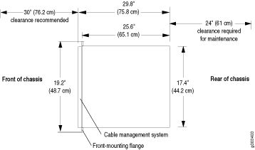
Clearance Requirements for SRX5400 Firewall Airflow and Hardware Maintenance
When planning the installation site, you need to allow sufficient clearance around the rack (see Figure 1):
For the cooling system to function properly, the airflow around the chassis must be unrestricted. Allow at least 8 in. (20.32 cm) of side clearance between side-cooled devices. Allow 5.5 in. (13.97 cm) between the side of the chassis and any non-heat-producing surface such as a wall.
A minimum of 3 inches clearance must be provided behind the power supplies for airflow.
For service personnel to remove and install hardware components, there must be adequate space at the front and back of the firewall. At least 24 in. (61 cm) is required both in front of and behind the device. NEBS GR-63 recommends that you allow at least 30 in. (76.2 cm) in front of the firewall.