SRX4700 Power Supply Maintenance
Maintaining an SRX4700 includes removing a failed power supply unit (PSU) and installing a functional PSU.
Maintain the Power Supplies
Purpose
For optimum firewall performance, verify the condition of the power supplies.
Action
On a regular basis check the power supply status:
-
Issue the
show chassis powerCLI command. -
Arrange the power and grounding cables in a way so that they do not obstruct access to other firewall components.
-
Routinely check the status LEDs on the power supply faceplates and the chassis LEDs to determine whether if the PSUs are functioning normally.
-
Check the red and yellow alarm LEDs on the chassis LEDs. If a PSU fails or you remove a PSU, it triggers an alarm that causes one or both LEDs to light. To find out the associated error messages, issue the following command:
user@host> show chassis alarms -
Periodically inspect the site to ensure that the grounding and power cables connected to the firewall are securely in place and that there's no moisture accumulating near the firewall.
Do not mix AC and DC PSUs in the same chassis.
Replace an AC PSU on the SRX4700
The SRX4700 rear panel has two AC PSUs, which are hot-removable and hot-insertable field-replaceable units (FRUs). You can remove and replace the PSUs without powering off the SRX4700 or disrupting the firewall functions.
Ensure that you have the following parts and tools:
-
An electrostatic discharge (ESD) grounding strap
-
An antistatic bag or an antistatic mat
-
A replacement AC PSU
-
A blank cover panel (in case you're not replacing the component)
Remove an AC PSU from the SRX4700
Before you remove a PSU, be aware of the following:
Avoid leaving the PSU slot empty for more than 30 minutes when the device is operational. For proper airflow, you must place the PSU in the chassis. Always cover the empty PSU slot with a blank panel.
The minimum required number of PSUs must be present in the firewall at all times.
After powering off a PSU, wait at least 60 seconds before turning it back on.
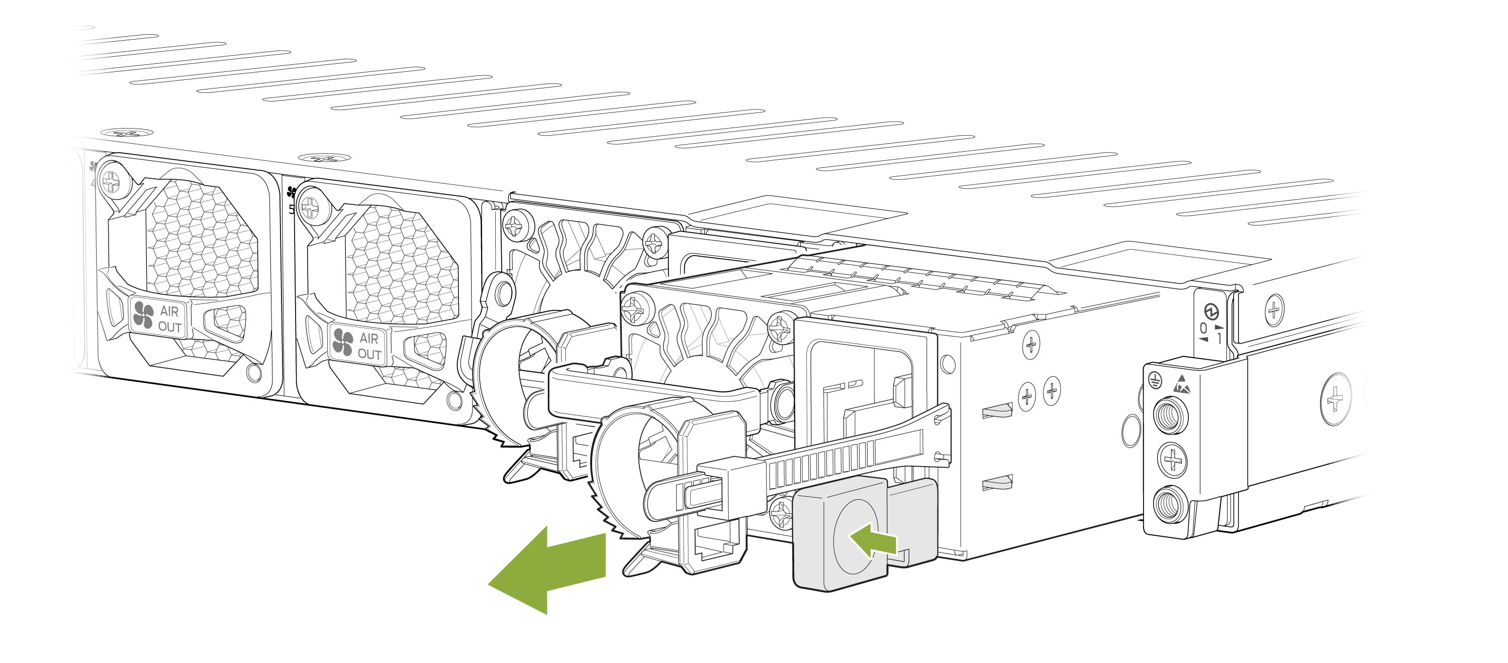
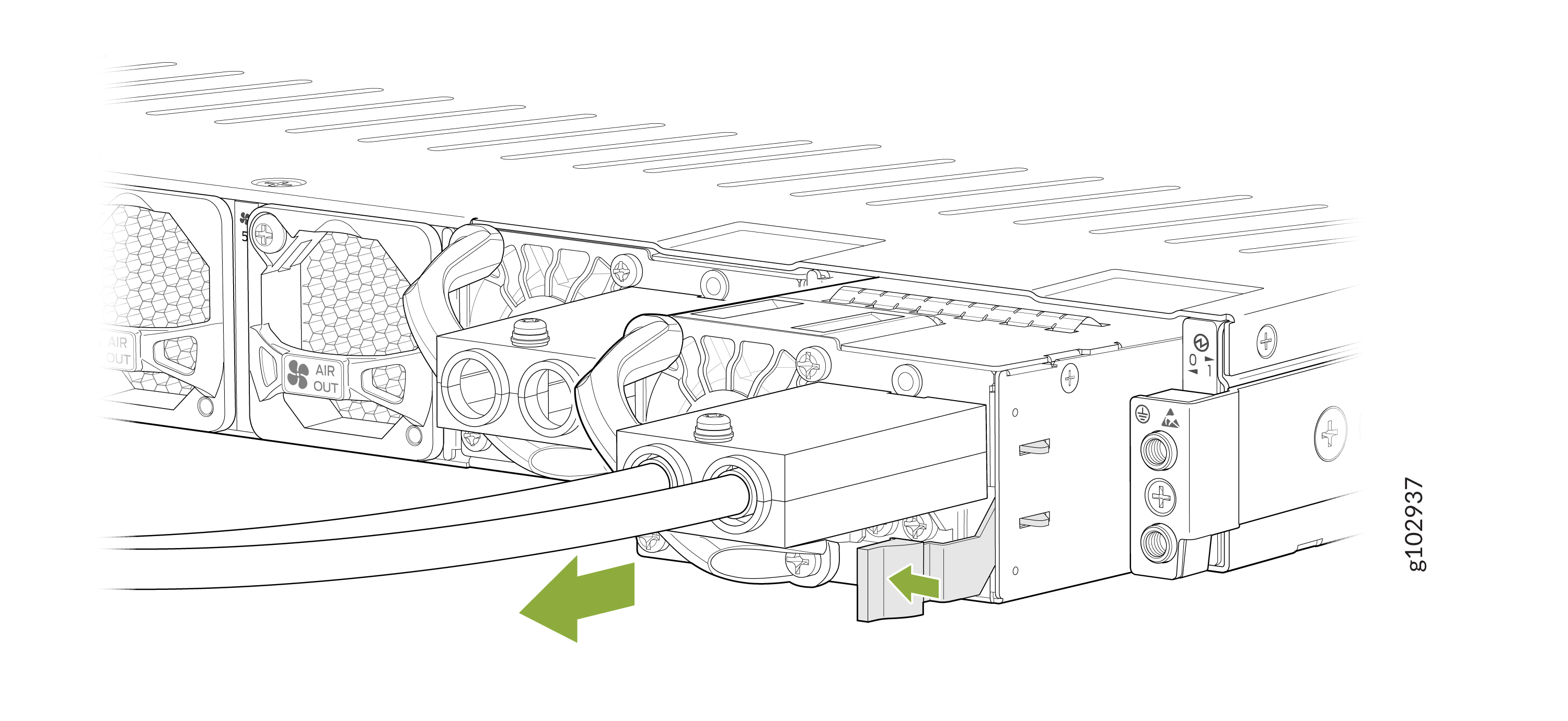
To remove an AC PSU:
-
Press the release latch on the right side of the AC PSU to disconnect
the PSU from the chassis.
Install an AC PSU in the SRX4700
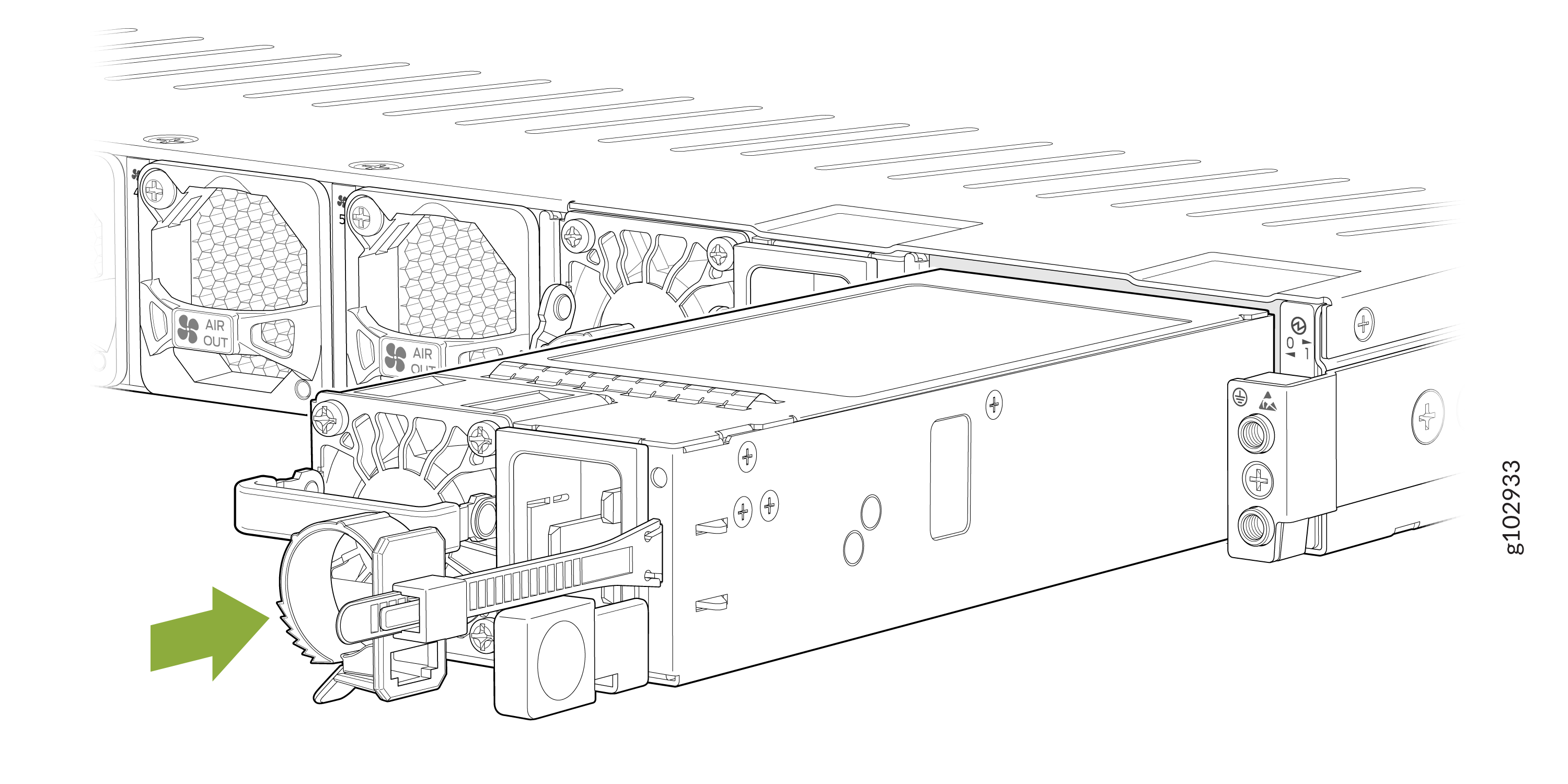
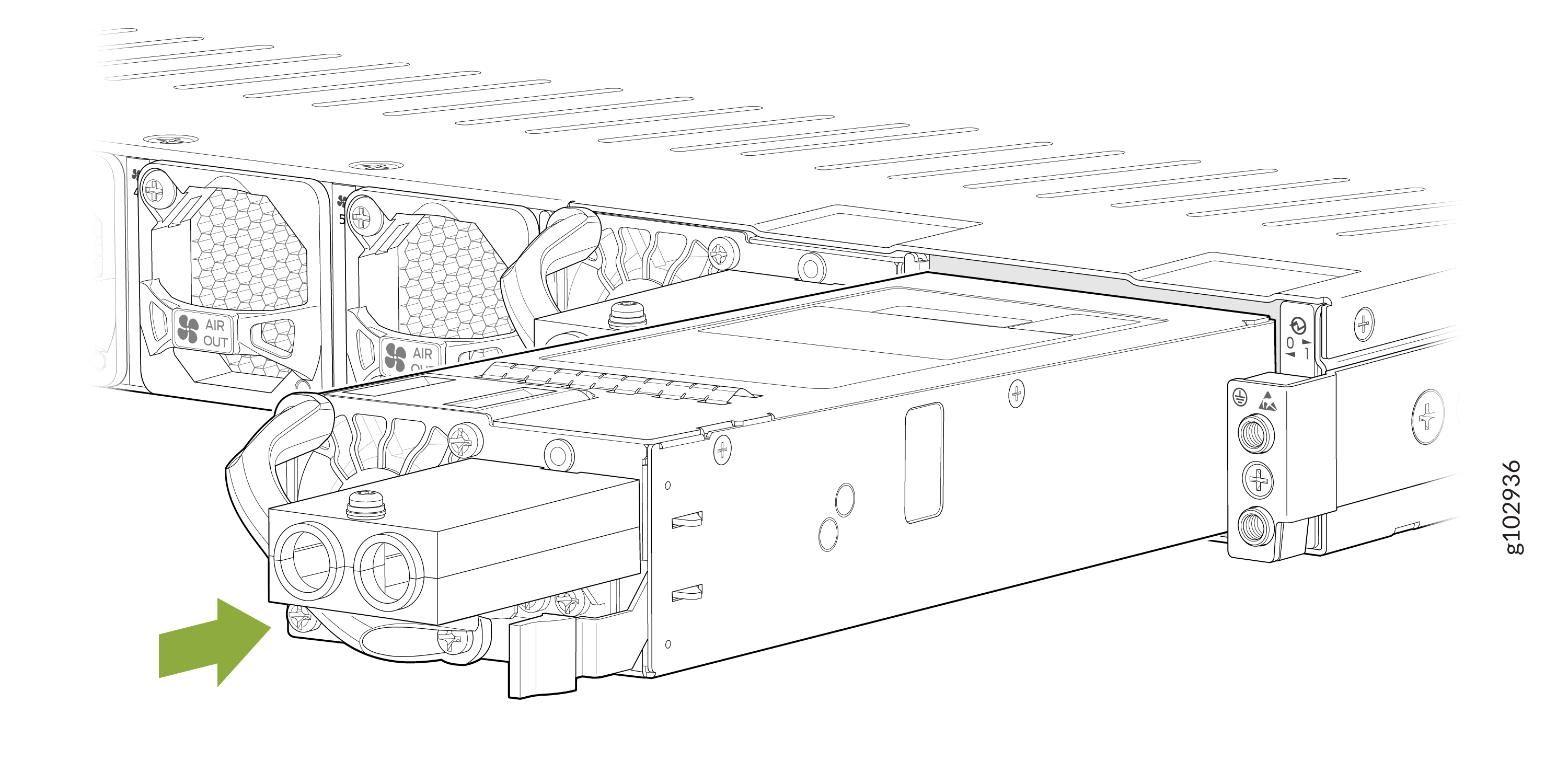
To install an AC PSU:
-
Using both hands, hold and slide the AC PSU straight into the chassis
until the PSU is fully seated in the chassis slot.
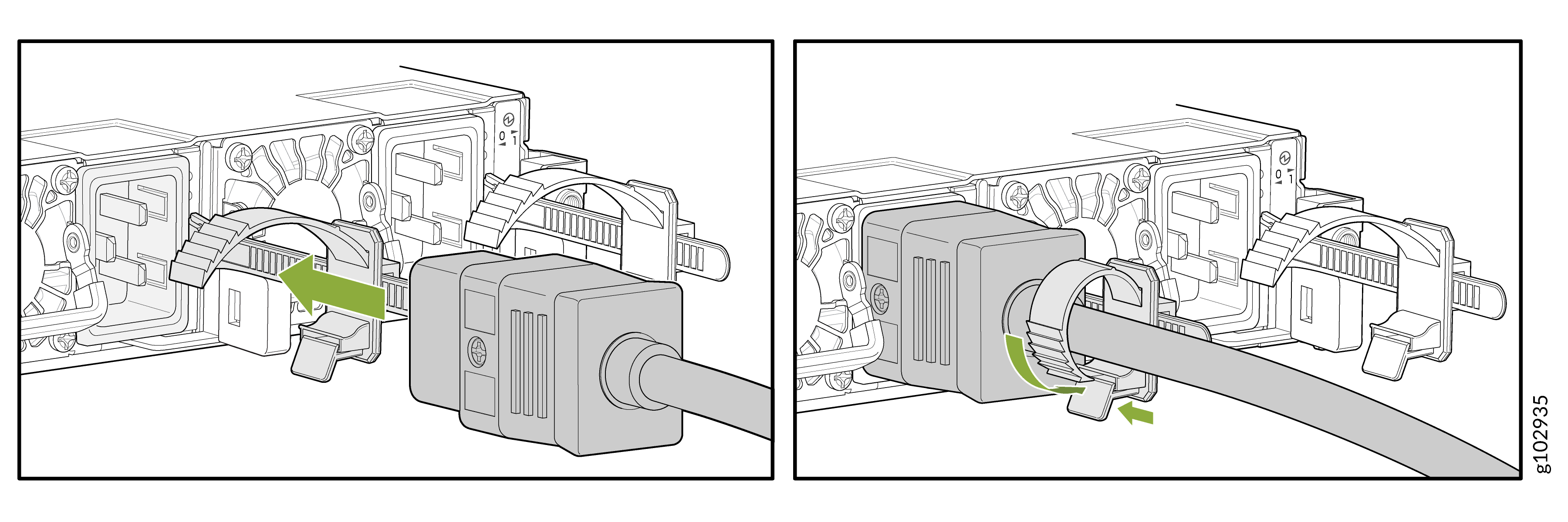
-
Push the retainer clip through the loop and tighten it until it fits
snug around the power cord.
Replace a DC PSU on the SRX4700
The rear panel of the SRX4700 has two DC PSUs, which are hot-removable and hot-insertable field-replaceable units (FRUs). You can remove and replace the PSUs without powering off the SRX4700 or disrupting the firewall functions.
Ensure that you the following parts and tools are available:
-
An ESD grounding strap
-
Phillips (+) screwdriver, Number 1 and Number 2
-
An antistatic bag or an antistatic mat
-
A replacement DC PSU
-
A blank cover panel (in case you're not replacing the component)
Remove a DC PSU from the SRX4700
Before you remove a PSU, be aware of the following:
Avoid leaving the PSU slot empty for more than 30 minutes when the device is operational. For proper airflow, you must place the PSU in the chassis. Always cover the empty PSU slot with a blank panel.
The minimum required number of PSUs must be present in the firewall at all times.
After powering off a PSU, wait at least 60 seconds before turning it back on.
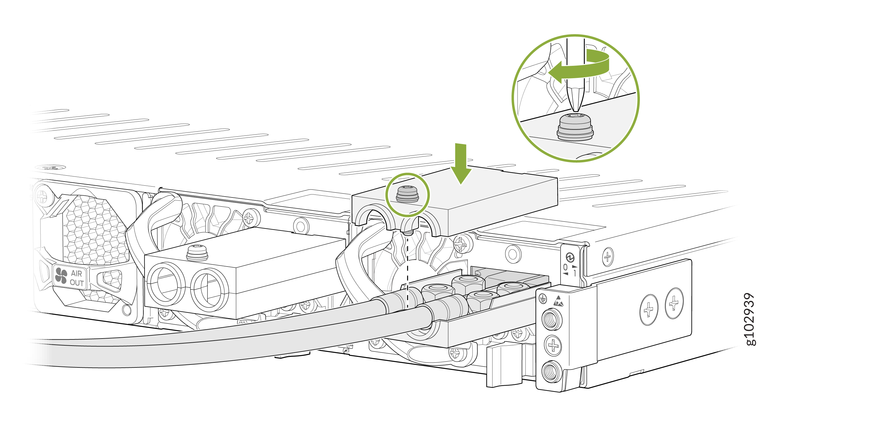
To remove a DC PSU from the firewall:
-
Pull the PSU straight out of the chassis.
-
Using a screwdriver (anticlockwise), unscrew the nut on top of the
terminal block and remove the terminal block cover.
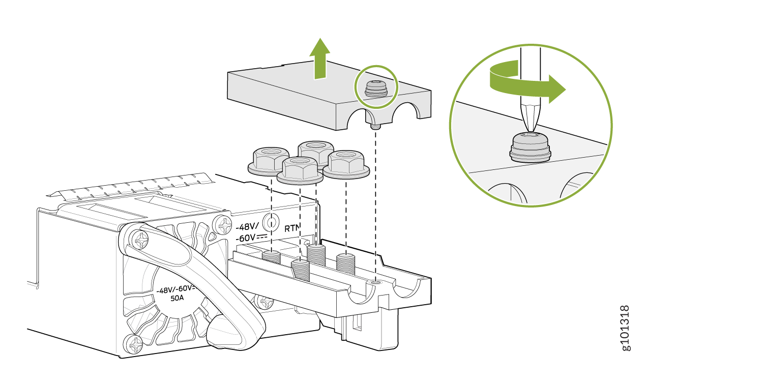
-
Remove the nuts and cables from the four terminals.
Install a DC PSU in the SRX4700
Before you perform DC power procedures, ensure there is no power to the DC circuit. To ensure that all power is off, locate the circuit breaker on the panel board that services the DC circuit, switch the circuit breaker to the off position, and tape the switch handle of the circuit breaker in the off position.
To install a DC PSU:
-
Using both hands, slide the DC PSU straight into the chassis until the
PSU is fully seated in the chassis slot. The PSU faceplate must align
with any adjacent PSU faceplate installed in the PSU slot.
-
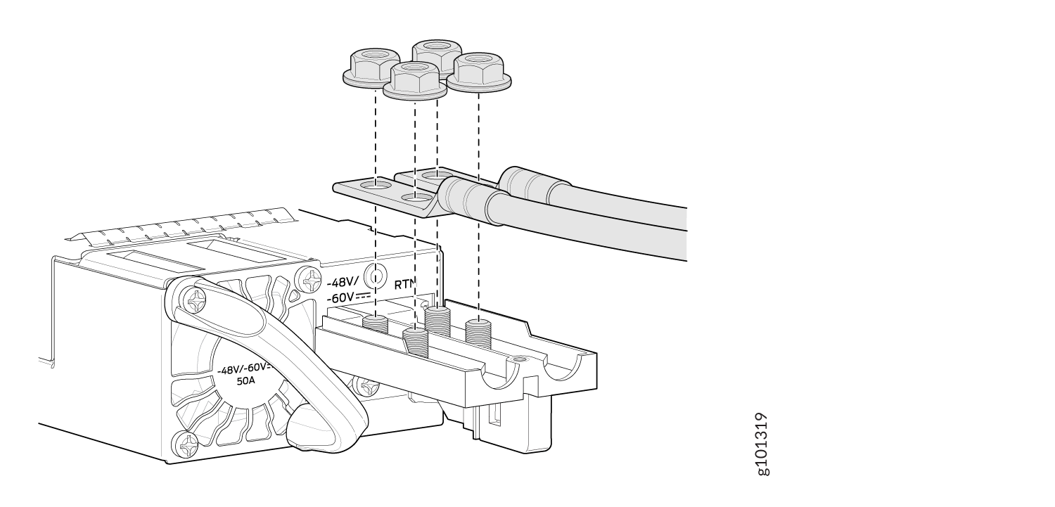
Remove the nuts from the four terminals.
-
Secure each power cable lug to the terminal with the nuts. Use the
screwdriver to tighten the nuts on the PSU terminals until snug. Apply
between 23 lbf-in. (2.6 Nm) to 25 lbf-in. (2.8 Nm) of torque to the
nuts. Use a socket nutdriver to ensure you don't overtighten the
nuts.
-
Secure the positive (+) DC source power cable lug to the RTN (return) terminal.
-
Secure the negative (–) DC source power cable lug to the –48V/-60V (input) terminal.
CAUTION:Ensure that each power cable lug seats flush against the surface of the terminal block as you are tightening the nuts. Ensure that each nut is properly threaded into the terminal. Applying installation torque to the nuts when improperly threaded can result in damage to the terminal.
CAUTION:You must ensure that power connections maintain the proper polarity. The power source cables might be labeled (+) and (–) to indicate their polarity. There is no standard color coding for DC power cables. The color coding used by the external DC power source at your site determines the color coding for the leads on the power cables that attach to the terminal studs on each power supply.
-
-
Place the terminal block cover on and tighten the screw.