SRX4700 Chassis
The SRX4700 Firewall chassis is a rigid sheet metal structure that houses all the other hardware components.
Chassis Physical Specifications for SRX4700
The SRX4700 Firewall has a 1-U form factor and can be installed in a standard 19-inch rack.
| Model | Height | Width | Depth | Weight |
|---|---|---|---|---|
|
SRX4700 chassis |
1.72 in. (4.37 cm) |
17.28 in. (43.9 cm) |
26.89 in. (68.31 cm) |
32.85 lb (14.9 kg) |
|
SRX4700 chassis with AC PSUs |
27.29 in (69.32 cm) |
40 lb (18.2 kg) |
||
|
SRX4700 chassis with DC PSUs |
29.20 in (74.17 cm) |
42 lb (19.1 kg) |
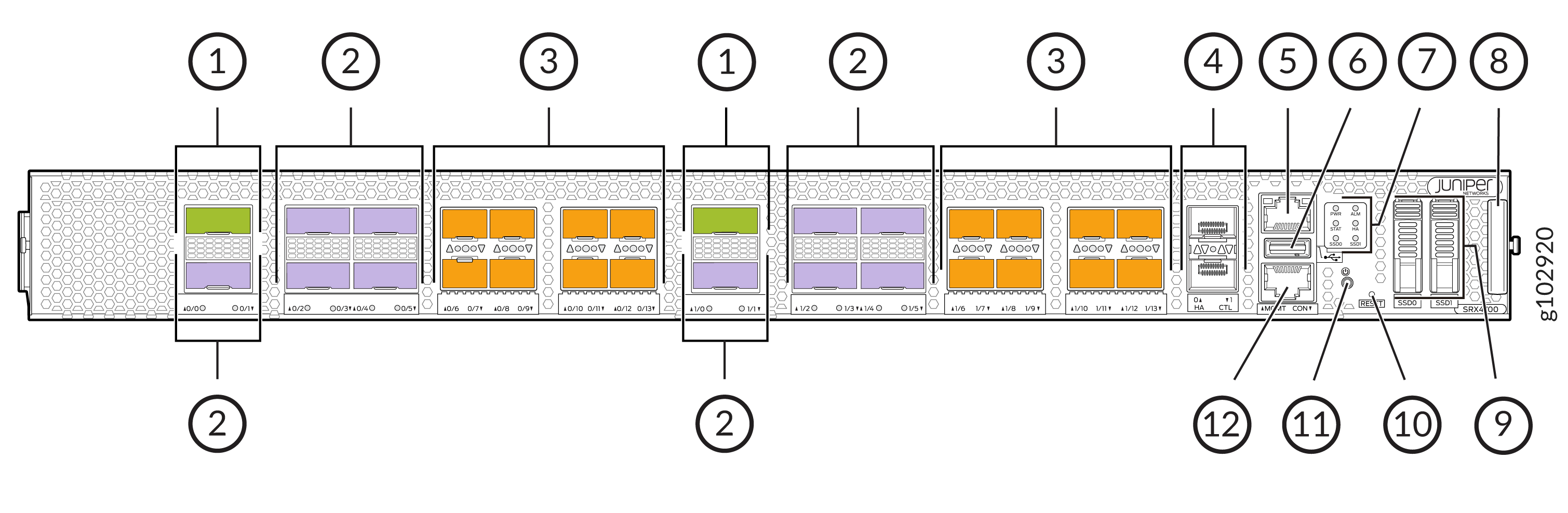
Chassis Front Panel
|
Callout |
Component (Label on the Chassis) |
Description |
|---|---|---|
|
1 |
QSFP56-DD ports |
Two 400-Gigabit Ethernet (400 GbE) QSFP56-DD MACsec ports for network traffic |
|
2 |
QSFP28 ports |
Ten 100 GbE QSFP28 MACsec ports for network traffic |
|
3 |
SFP56 ports |
Sixteen 50 GbE SFP56 MACsec ports for network traffic |
|
4 |
HA ports |
Two 1 GbE SFP high availability CTL ports with MACsec support |
|
5 |
Management port (MGMT) |
1-Gigabit Ethernet RJ-45 port |
|
6 |
USB port |
One USB 3.0 Type A port that accepts a USB storage device |
|
7 |
Chassis LEDs |
Indicate component and system status and troubleshoot information at a glance |
|
8 |
Pull-out information tab |
Contains the serial number |
|
9 |
SSD0 |
1-TB SSD |
|
SSD1 |
2-TB SSD |
|
|
10 |
RESET |
Reset button. To reset the firewall, press and hold the RESET button for around 250 ms |
|
11 |
Power button |
Power button To power on the firewall press and hold the button for 250ms To power off the firewall press and hold the button for 4 seconds |
|
12 |
Console port (CON) |
You can connect a laptop to the SRX4700 for CLI management. The port uses an RJ-45 serial connection and supports the RS-232 (EIA-232) standard |
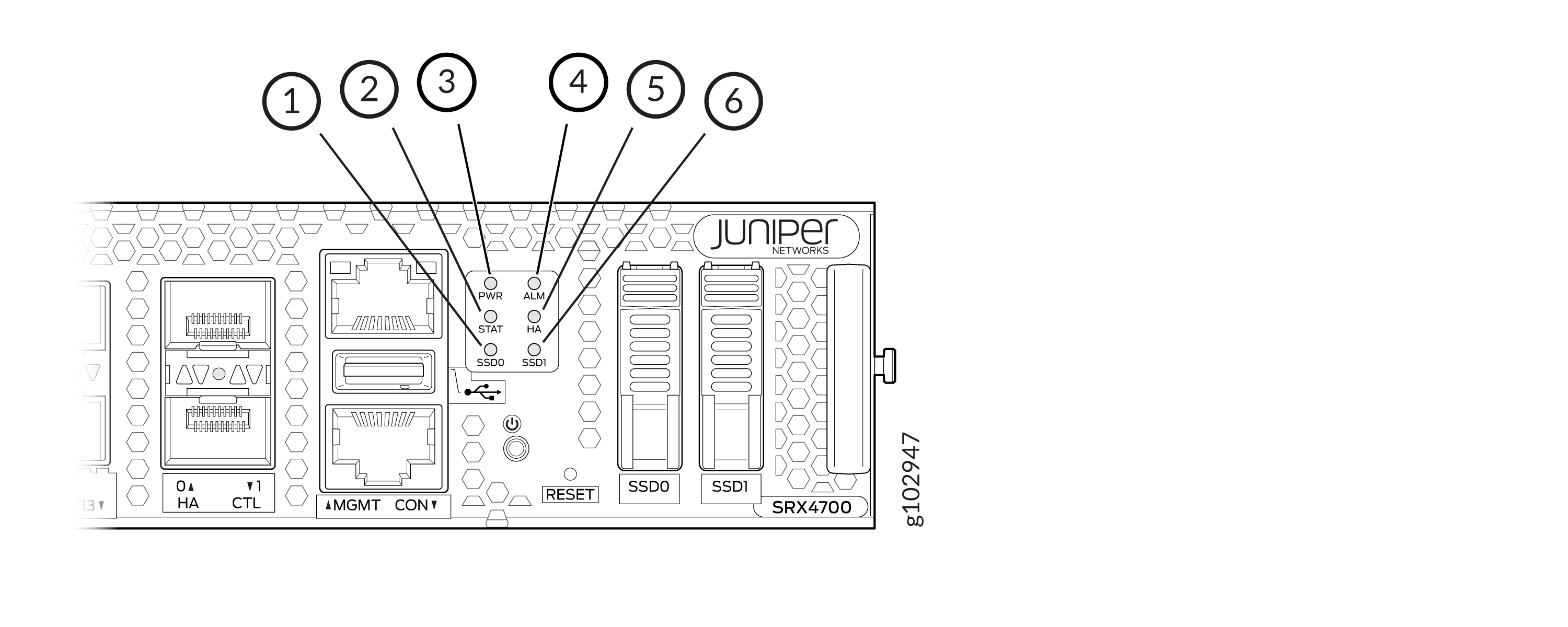
Chassis Status LEDs
| Callout | LED | Description |
|---|---|---|
|
1 |
SSD0 |
|
|
2 |
STAT |
|
|
3 |
PWR |
|
|
4 |
ALM |
|
|
5 |
HA |
|
|
6 |
SSD1 |
|
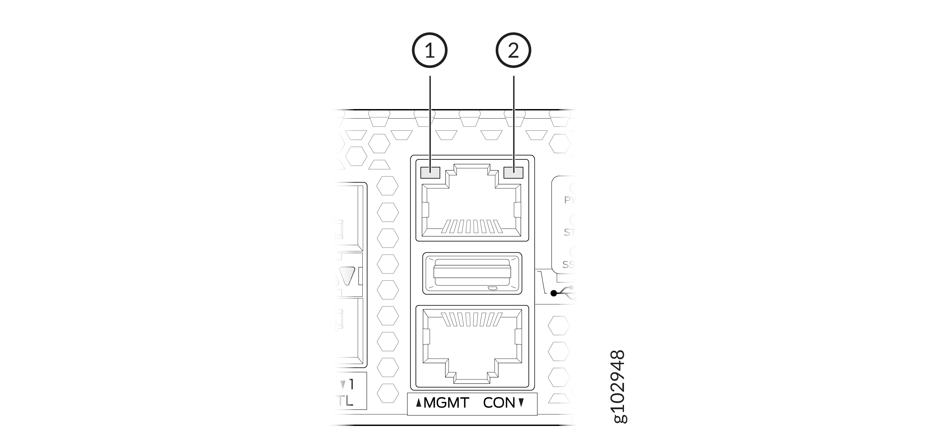
Management Port LEDs
| Callout | LED | Description |
|---|---|---|
| 1 | Link (LED on the left) |
|
| 2 | Activity (LED on the right) |
|
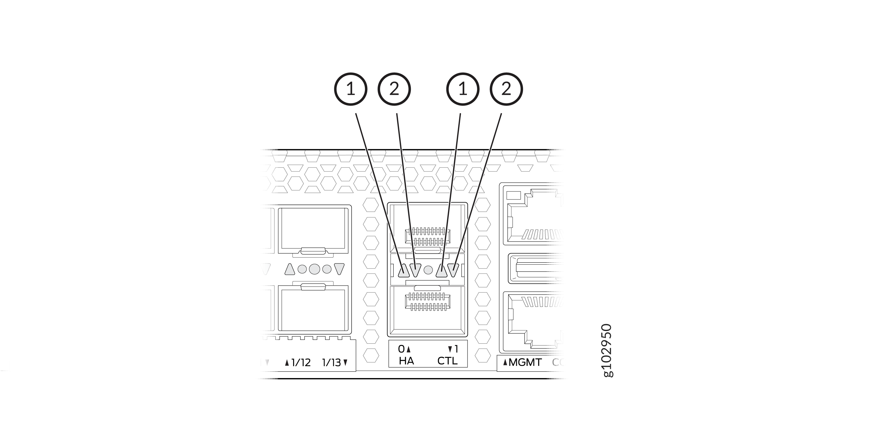
HA Port LEDs
| Callout | LED | Description |
|---|---|---|
| 1 | Link (LED on the left) |
|
| 2 | Activity (LED on the right) |
|
Network Port LEDs
Each SRX4700 network port uses a single bicolored LED to indicate link status or a fault condition.
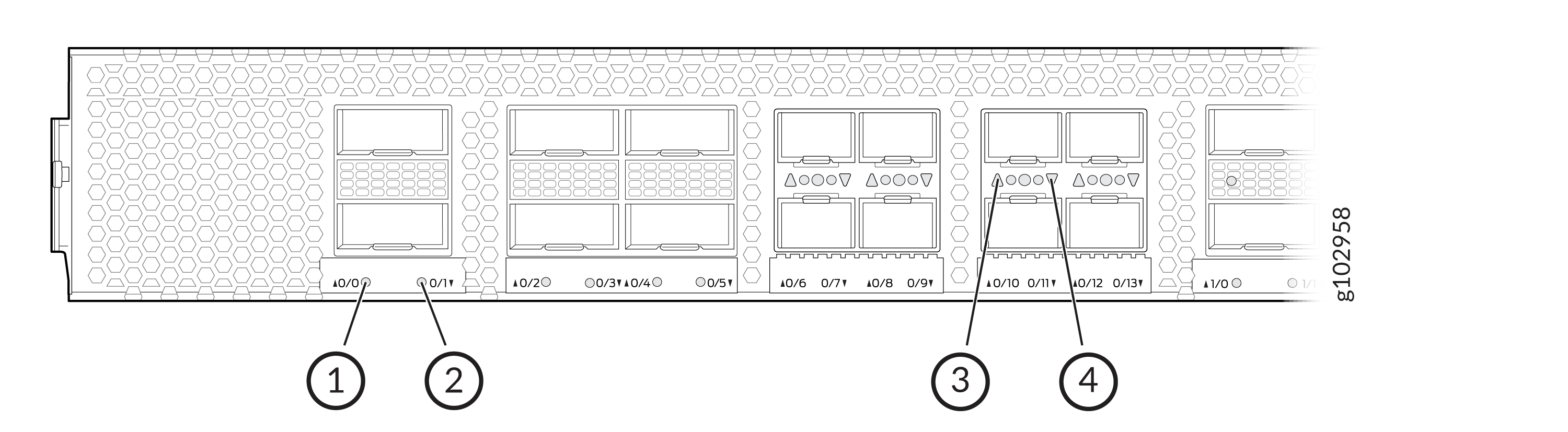
-
Link status LED of QSFP56-DD port 0/0
-
Link status LED of QSFP28 port 0/1
-
Link status LED of SFP56 port 0/10
-
Link status LED of SFP56 port 0/11
The number next to the LED indicates the port number to which the LED belongs. All network port LEDs behave the same. Table 2 describes the network port LEDs on SRX4700 Firewall, their colors and states, and the status that they indicate.
| LED Color | LED State | Description |
|---|---|---|
|
Unlit |
Off |
This indicates one of the following events:
|
|
Green |
On steadily |
Link is established, and there is link activity. |
|
Amber |
On steadily |
Port link is down or the port encountered errors such as loss of signal, local fault, or remote fault. |
|
Red |
On steadily |
The link is down because the port/transceiver has a hardware failure. |
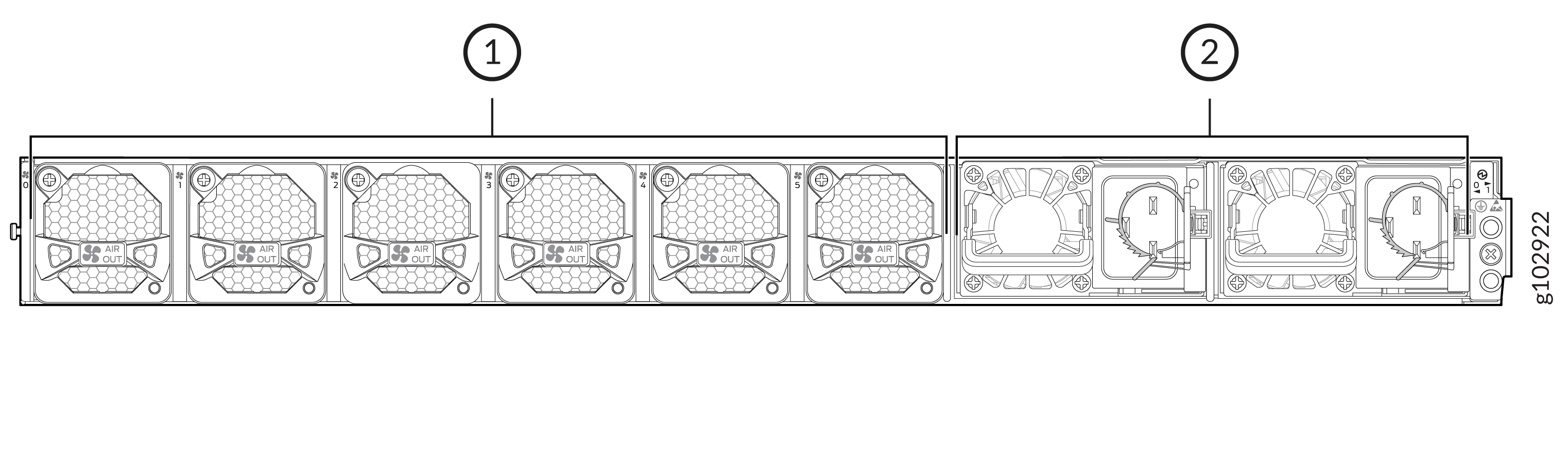
Chassis Rear Panel
| Callout |
Component |
Description |
|---|---|---|
|
1 |
Fan modules |
Six airflow out (AFO) fan modules (5+1 redundancy). Five fan modules are required for proper airflow across the chassis internal components. The sixth fan module provides redundancy. |
|
2 |
Power supply unit (PSU) |
Two 2200 W AC PSUs provided with the SRX4700. |
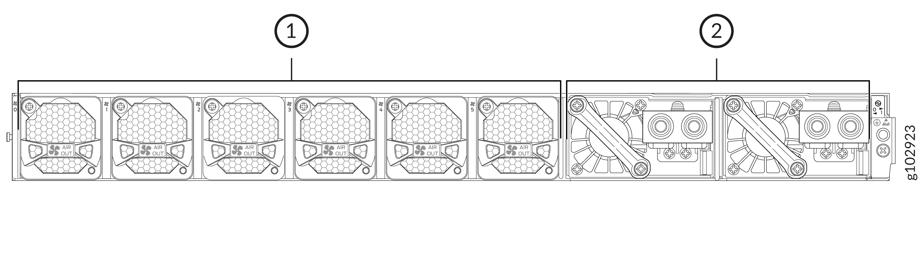
| Callout |
Component |
Description |
|---|---|---|
|
1 |
Fan modules |
Six airflow out (AFO) fan modules (5+1 redundancy). Five fan modules are required for proper airflow across the chassis internal components. The sixth fan module provides redundancy. |
|
2 |
Power supply unit (PSU) |
Two 2200 W DC PSUs provided with the SRX4700. |