SRX4300 Chassis
The SRX4300 Firewall chassis is a rigid sheet metal structure that houses all the other hardware components.
Chassis Physical Specifications for SRX4300
The SRX4300 Firewall has a 1RU form factor and can be installed in a standard 19-inch rack. Table 1 summarizes the physical specifications of SRX4300.
| Model | Height | Width | Depth | Weight |
|---|---|---|---|---|
| SRX4300 | 1.74 in. (4.42 cm) | 17.28 in. (43.89 cm) | 18.20 in. (46.23 cm) | 18.30 lb (8.3 kg) |
We ship the SRX4300 with only one power supply unit (PSU). The weight of an SRX4300 device configured with 2 PSUs is 20.5 lb (9.3 kg).
Chassis Electrical Specifications for SRX4300
|
Item |
Specification |
|---|---|
|
AC input voltage |
Operating range: 100-127 VAC / 200-240 VAC |
|
AC input line frequency |
50/60 Hz |
|
AC input current rating |
10.52 A at 100-127 VAC 5.26 A at 200-240 VAC |
|
DC input voltage |
-40 VDC through -72 VDC |
|
DC input current rating |
24 A maximum |
Front Panel of an SRX4300
Figure 1 shows the front panel of an SRX4300.
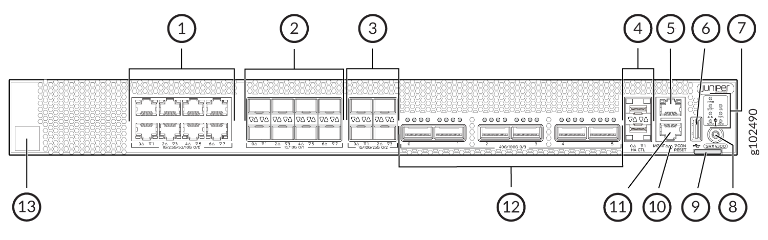
Table 3 lists and describes the front panel components of the firewall.
|
Callout |
Component (Label on the Chassis) |
Description |
|---|---|---|
| 1 |
Ethernet ports |
Eight 1/2.5/5/10-Gigabit Ethernet MACsec ports for network traffic. |
| 2 |
SFP+ ports |
Eight 1/10-Gigabit Ethernet SFP+ MACsec ports for network traffic. |
| 3 |
SFP28 ports |
Four 1/10/25-Gigabit Ethernet SFP28 MACsec ports for network traffic. |
| 4 |
Chassis cluster ports (HA) |
Two 1-Gigabit Ethernet SFP chassis cluster control CTL ports with MACsec support |
| 5 |
Management port (MGMT) |
1-Gigabit Ethernet RJ-45 port |
| 6 |
USB port |
One USB 3.0 Type A port that accepts a USB storage device. |
| 7 | Chassis LEDs |
Indicate component and system status and troubleshooting information at a glance. |
| 8 |
Power button |
Power button |
| 9 | Pull tab | Contains the CLEI code and serial number of the device. |
| 10 |
RESET |
Reset button. To reset the system, press and hold the RESET button for around 250 ms. |
| 11 |
Console port (CON) |
You can connect a laptop to the SRX4300 for CLI management. The port uses an RJ-45 serial connection and supports the RS-232 (EIA-232) standard. |
| 12 |
QSFP28 ports |
Six 4x10/4x25/2x50/40/100-Gigabit Ethernet QSFP28 MACsec ports for network traffic. |
| 13 |
Claim code |
You can use the QR code to claim and onboard your device to Juniper Security Director. |
See the Hardware Compatibility Tool for a list of all supported optics for the SRX4300.
Rear Panel of an SRX4300
Figure 2 shows the rear panel of the AC variant of the SRX4300.
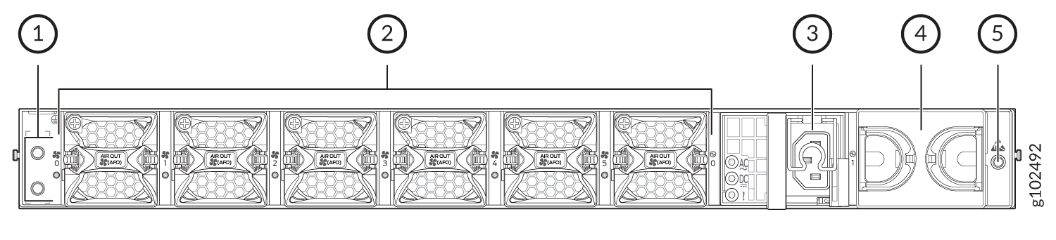
Table 4 lists and describes the rear panel components of the AC variant of the SRX4300.
| Callout |
Component |
Description |
|---|---|---|
| 1 | Grounding point | Grounding point |
| 2 |
Fan modules |
Six airflow out (AFO) fan modules (5+1 redundancy). Five fan modules are required for proper airflow across the chassis internal components. The sixth fan module provides redundancy. |
| 3 |
PSU (Power Supply Unit) |
A 850W AC PSU is provided with the SRX4300. |
| 4 | Empty PSU slot | Blank slot to install an additional PSU (1+1 redundancy). |
| 5 | ESD | ESD socket |
We ship the SRX4300 with only one power supply. You can order the second power supply separately, if required.
You must not mix AC and DC power supplies in the same chassis.
Figure 3 shows the rear panel of the DC variant of the SRX4300.
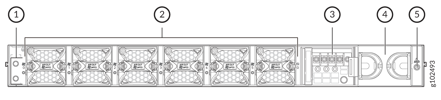
Table 5 lists and describes the rear panel components of the DC variant of the SRX4300.
| Callout |
Component |
Description |
|---|---|---|
| 1 | Grounding point | Grounding point |
| 2 |
Fan modules |
Six airflow out (AFO) fan modules (5+1 redundancy). Five fan modules are required for proper airflow across the chassis internal components. The sixth fan module provides redundancy. |
| 3 |
PSU (Power Supply Unit) |
A 850W DC PSU is provided with the SRX4300. |
| 4 | Empty PSU slot | Blank slot to install an additional PSU (1+1 redundancy). |
| 5 | ESD | ESD socket |
We ship the SRX4300 with only one power supply. You can order the second power supply separately, if required.
You must not mix AC and DC power supplies in the same chassis.
Chassis Status LEDs
Figure 4 shows the LEDs on the front panel.
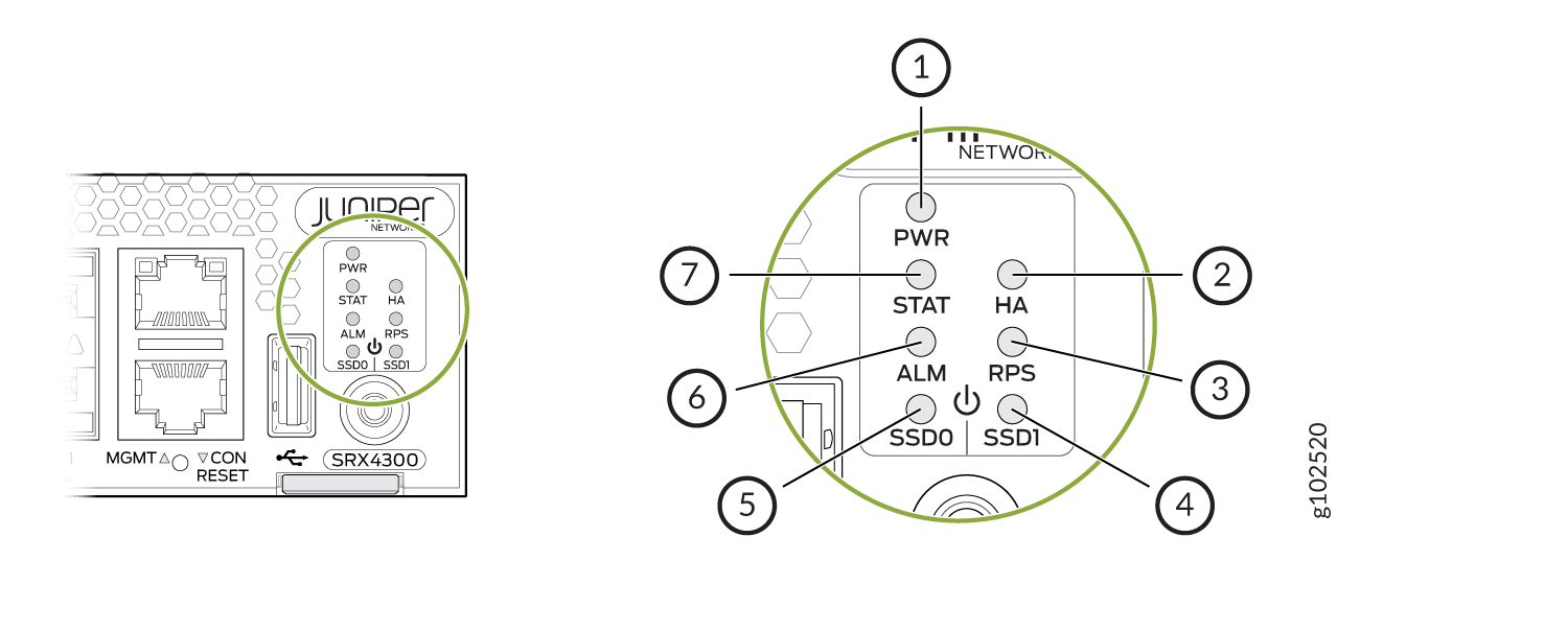
| Callout | LED | Description |
|---|---|---|
| 1 | PWR |
|
| 2 | HA |
|
| 3 | RPS |
|
| 4 and 5 | SSD0 and SSD1 |
|
| 6 | ALM |
|
| 7 | STAT |
|
Management Port LEDs
Figure 5 shows the LEDs for the management ports.
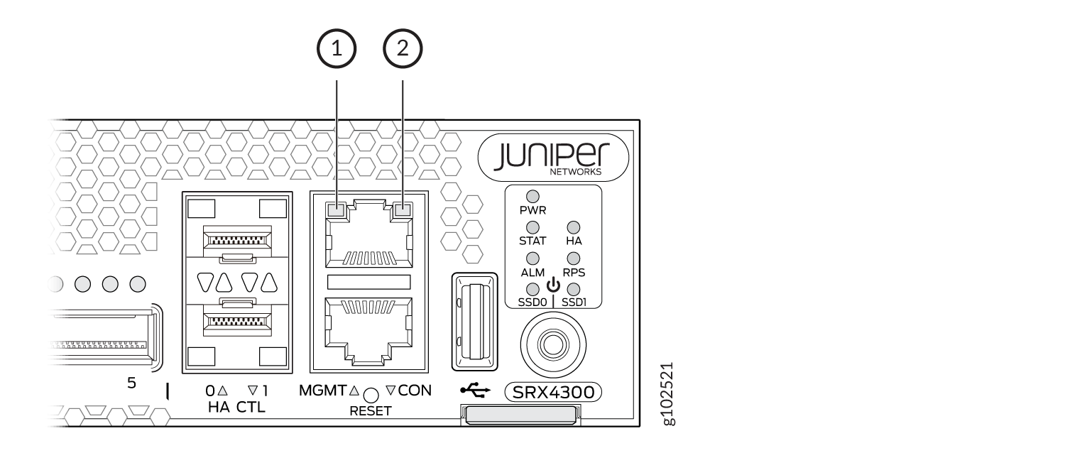
| Callout | LED | Description |
|---|---|---|
| 1 | Link (LED on the left) |
|
| 2 | Activity (LED on the right) |
|
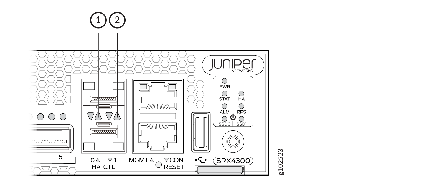
Network Port LEDs
The BASE-T, SFP+, and SFP28 ports have two LEDs to indicate the link activity and status. Figure 6 shows the location of the LEDs on the BASE-T ports and Table 8 describes the LED behaviour.
| Callout 1 | Callout 2 | Description (for RJ-45, SFP, SFP+, and SFP28 ports) |
|---|---|---|
|
Status LED (Left LED) |
Link and Activity LED (Right LED) |
|
| Off | Off | Default (power on with or without Transceiver) |
| Solid Green | Solid Green | 25 Gbps link is up but there is no traffic on the port. |
| Blinking Green | 25 Gbps link is up and there is traffic on the port. | |
| Blinking Green | Solid Green | 10 Gbps link is up but there is no traffic on the port. |
| Blinking Green | 10 Gbps link is up and there is traffic on the port. | |
| Off | Solid Green | 1 Gbps link is up but there is no traffic on the port. |
| Blinking Green | 1 Gbps link is up and there is traffic on the port. | |
| Off | Off | This indicates one of the following:
|
The QSFP28 ports have four LEDs to indicate the link activity and status. Figure 7 shows the location of the LEDs on the QSFP28 ports and Table 9 describes the LED behaviour.
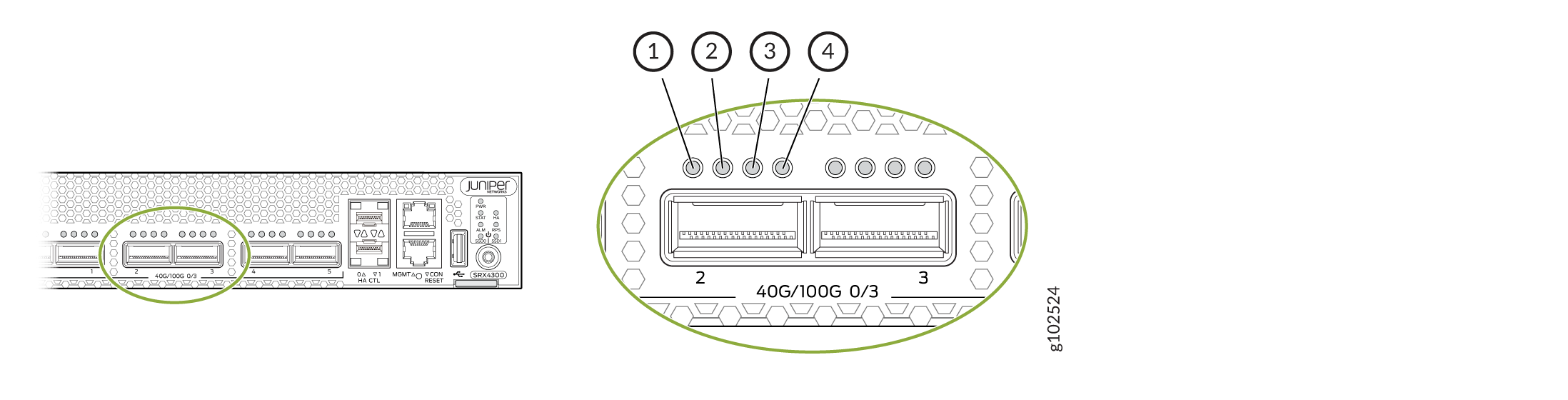
| LED | State | Description |
|---|---|---|
| 1 (non-channelized) | Solid Green | 100 Gbps or 40 Gbps link is up but there is no traffic on the port. |
| Blinking Green | 100 Gbps or 40 Gbps link is up and there is traffic on the port. | |
| 1-4 (channelized) | Solid Green | 4x25 Gbps or 4x10 Gbps link is up but there is no traffic on the port. |
| Blinking Green | 4x25 Gbps or 4x10 Gbps link is up and there is traffic on the port. | |
| 1-4 | Off | This indicates one of the following:
|
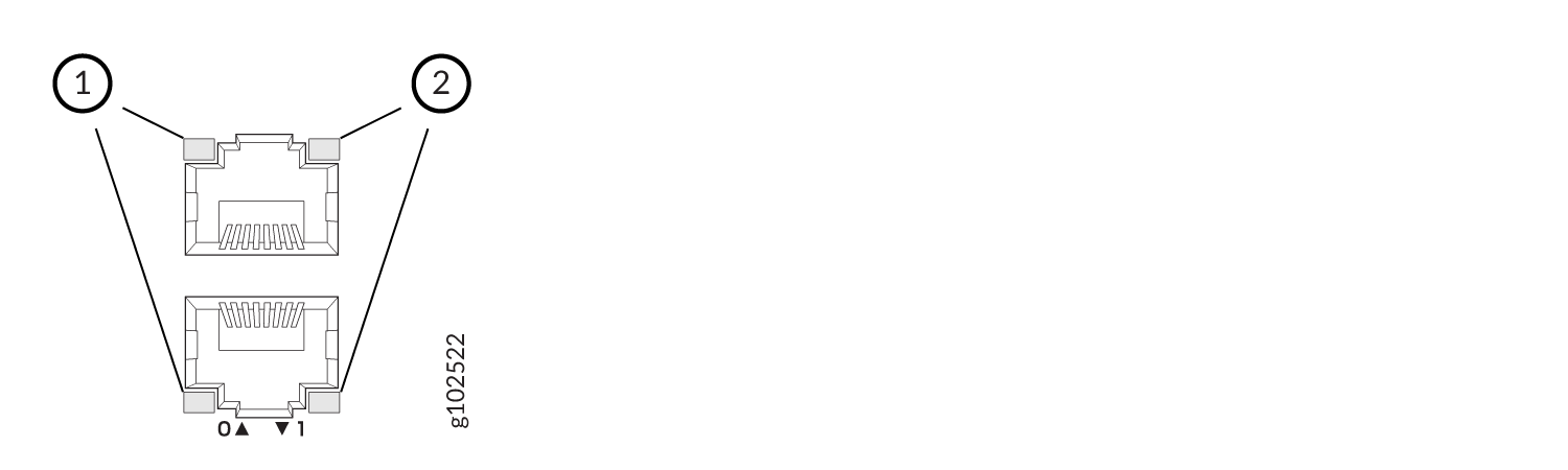
Figure 8 shows the location of the LEDs on the HA ports and Table 10 describes the LEDs.
| Callout | LED | Description |
|---|---|---|
| 1 | Link (LED on the left) |
|
| 2 | Activity (LED on the right) |
|