Connect the SRX4120 to Power
This section takes you through the steps and safety precautions to be foolowing while connnecting power to the SRX4120, to prevent equipment damage and personal injury.
Ground the SRX4120
To meet safety and electromagnetic interference (EMI) requirements and to ensure proper operation, you must connect the SRX4120 to an earth ground before you connect it to power.
Before you connect an earth ground to the protective earthing terminal of the device, ensure that a licensed electrician attaches an appropriate grounding terminal to the grounding cable you supply. Using a grounding cable with an incorrectly -attached terminal can damage the device.
Before connecting the device to an earth ground, ensure that you have the following parts and tools:
-
An electrostatic discharge (ESD) grounding strap.
-
A grounding cable for your device—The grounding cable must be 6 AWG (4.11 mm²) stranded wire and rated 90 °C or per local electrical code.
-
A grounding 2-hole terminal for your grounding cable—This attaches to the chassis grounding point. The Panduit LCD6-14A-L terminal lugs, or equivalent are sized for 6 AWG (4.11 mm²) power source cables.
-
Two pan head M5 x10 mm screws with integrated split washers (not provided)—The screws and washers are used to secure the grounding lug to the protective earthing terminal.
-
A Phillips screwdriver to tighten the screw.
You must install heat-shrink tubing insulation around the crimped section of the power cables and lugs.
To ground the SRX4120, connect a grounding cable to earth ground. Attach the grounding cable to the chassis grounding point. Under all circumstances, use this grounding connection to ground the chassis.
To ground the device:
-
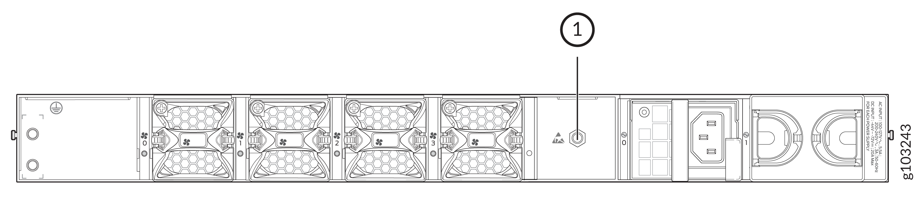
Wrap and fasten one end of the electrostatic discharge (ESD) grounding strap to
your bare wrist and connect the other end of the strap to the ESD point on the
chassis.
Figure 1: Chassis ESD point
-
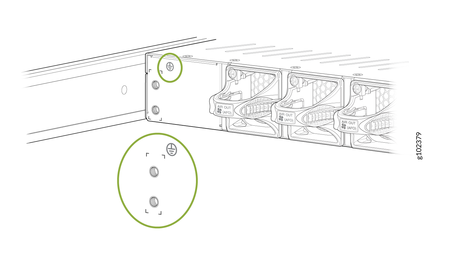
Locate the chassis grounding point.
Figure 2: Grounding Point on the SRX4120
-
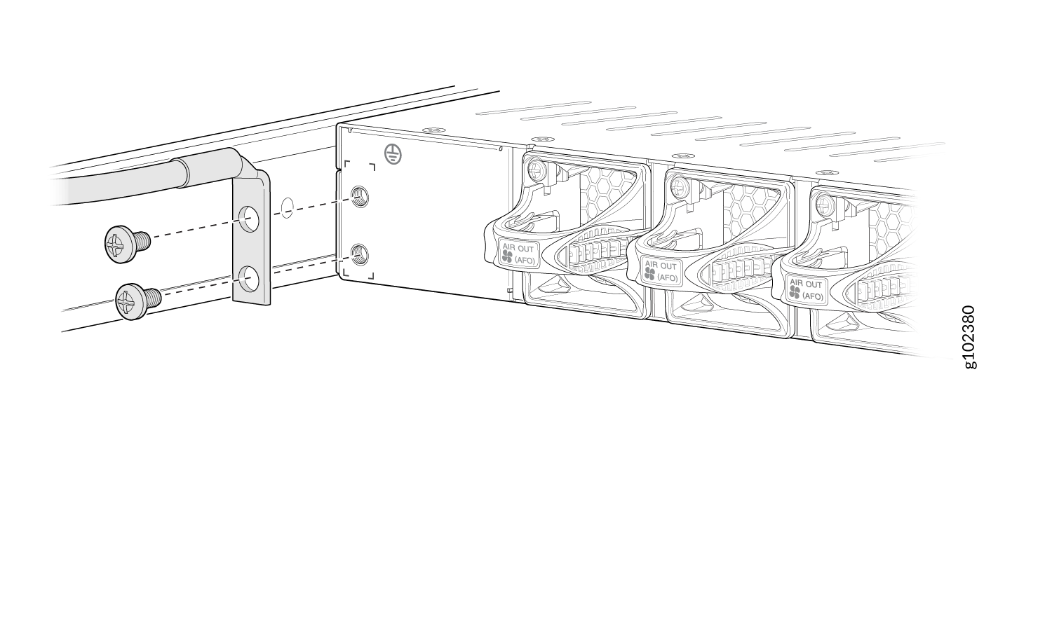
Secure the grounding cable terminal to the grounding point using M5 screws (not
provided).
Figure 3: Connect the Grounding Cable to the SRX4120
Install Heat-Shrink Tubing on a Power Cable
-
Shrink the tubing with a heat gun. Ensure that you heat all sides of the tubing evenly
so that it shrinks around the cable tightly.
CAUTION:
Do not overheat the tubing.
Figure 4: Install Heat-Shrink Tubing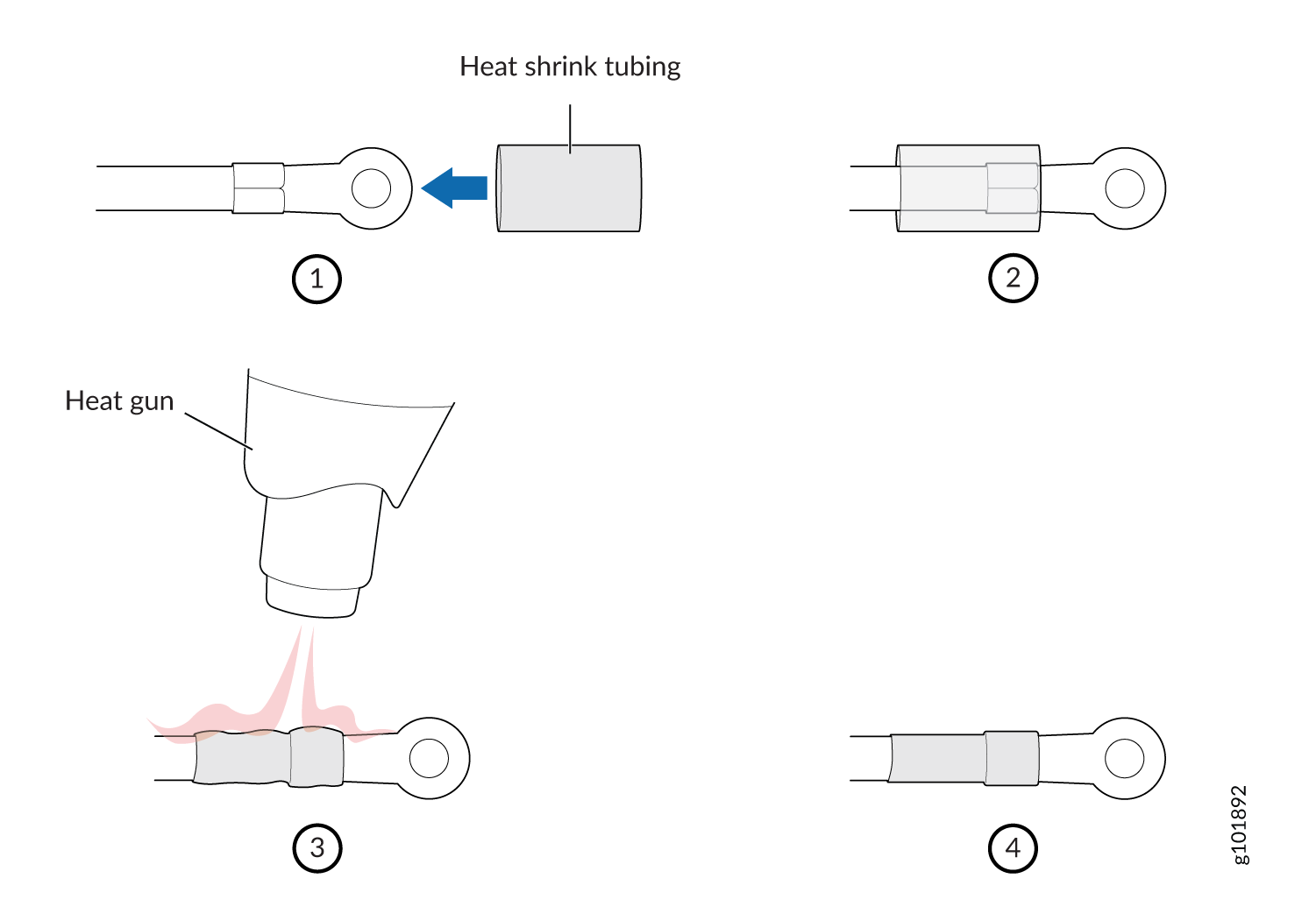
Connect AC Power to the SRX4120
Before you begin:
-
Ensure that you have grounded the SRX4120.
-
Ensure that you have read the guidelines and precautions in the Juniper Networks Safety Guide.
-
Ensure that you have a power cord appropriate for your geographical location available to connect AC power to the device.
-
Ensure that you fully insert the PSUs into the chassis.
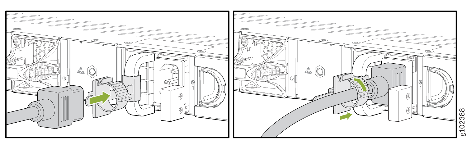
Connect the JPSU-450W-AC to Power
To connect the JPSU-450W-AC to AC power:
-
Push the power cord retainer onto the power cord.
Figure 5: Connect AC Power Cord
Connect DC Power to the SRX4120
Before you begin:
-
Ensure that you have grounded the SRX4120.
-
Ensure that you have installed heat-shrink tubing as described in Install Heat-Shrink Tubing on a Power Cable.
-
Ensure that you have read the guidelines and precautions in the Juniper Networks Safety Guide.
-
Ensure that you fully insert the PSUs into the chassis.
Before performing the following procedure, ensure that you remove the power from the DC circuit. To ensure that all power is off, locate the circuit breaker on the panel board that services the DC circuit. Switch the circuit breaker to the OFF position (0), and tape the switch handle of the circuit breaker in the OFF position.
Connect the JPSU-650W-DC-AFO to Power
The DC power cables for the JPSU-650W-DC-AFO are rated 16 AWG.
To connect the JPSU-650W-DC-AFO to power:
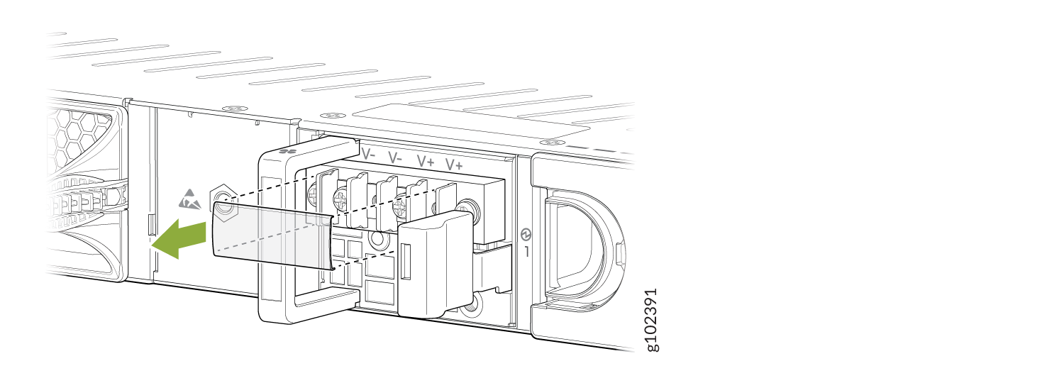
-
Remove the clear plastic cover that protects the terminal studs on the faceplate.
Figure 6: Remove the Terminal Cover
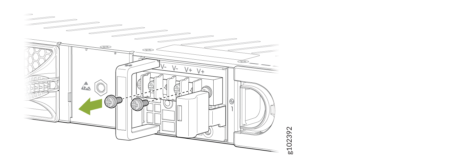
-
Remove the screws from the terminals, using a Phillips (+) screwdriver, number 2.
Figure 7: Remove the Screws
-
Secure each power cable ring terminal to the terminals with the screws.
-
Secure each positive (+) DC source power cable lug to an RTN (return) terminal.
-
Secure each negative (–) DC source power cable lug to a –48 V (input) terminal.
Figure 8: Connect the DC Power Cables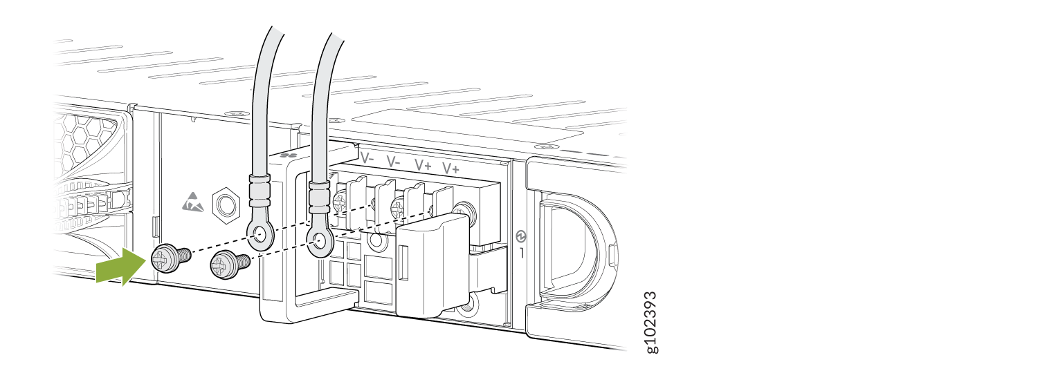 Note:
Note:Connect each power cable to a dedicated external circuit breaker. We recommend that you use a 10 A (80 VDC), or as permitted by the local code.
-
Power Off the SRX4120
You can power off the SRX4120 in any of the following ways:
-
Graceful shutdown:
-
Using hardware—Press and hold the Power button for atleast 4 seconds.
-
Using the CLI—Use the
request vmhost power-offcommand.
The device begins gracefully shutting down the operating system (OS) and then powers itself off.
CAUTION:Use the graceful shutdown method to power off or reboot the firewall.
-
-
Forced shutdown—Press the Power button and hold it for ten seconds. The device immediately powers itself off without shutting down the OS.
CAUTION:Use the forced shutdown method as a last resort to recover the firewall if the firewall OS is not responding to the graceful shutdown method.
To remove power completely from the device, unplug the AC power cord or DC power supply cable.
After powering off a PSU, wait at least 60 seconds before turning it back on. After powering on a PSU, wait at least 10 seconds before turning it off.
When the system is completely powered off and you turn on the power supply, the
device starts as the PSU completes its startup sequence. If the device finishes
starting and you need to power off the system again, first issue the
request vmhost halt command.
The fans in the PSU continue to rotate even after you power off the SRX4120. To stop the fans, remove the power cord from the PSU. The fans will stop in a few seconds.
After turning on the PSU, it can take up to 60 seconds for status indicators—such
as the PWR LED and the show chassis command display—to indicate
that the PSU is functioning normally. Ignore error indicators that appear during
the first 60 seconds.