SRX4120 Chassis LEDs
This topic describes the status LEDs for the chassis and ports on the SRX4120.
The LEDs on the SRX4120 indicate the status of the device and its components. You can also use the LEDs for troubleshooting.
Chassis Status LEDs
You can find the chassis status LEDs on the front panel of the SRX4120.
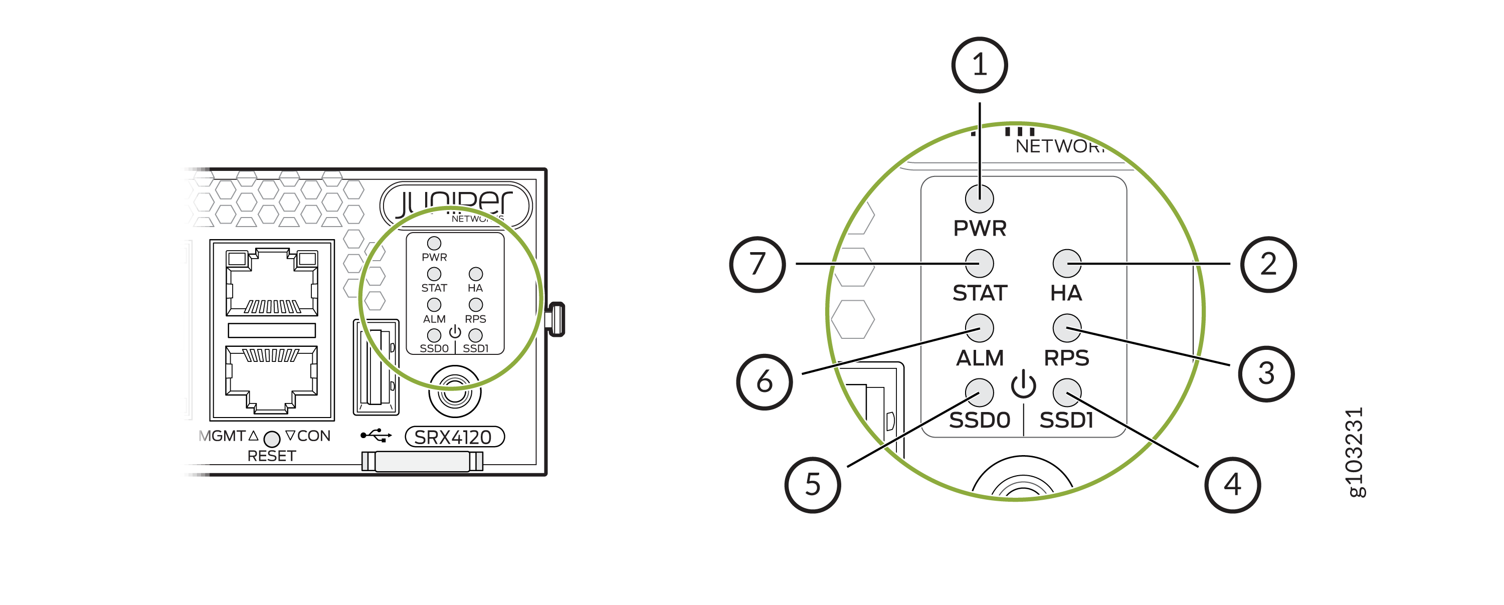
| Callout | Label | State | Description |
|---|---|---|---|
|
1 |
PWR |
Solid green |
The device is powered on. |
|
Blinking green |
The device is in the bootup phase before OS initialization. |
||
|
Solid red |
The power supply has failed and must be replaced. |
||
|
Off |
The device is powered off. |
||
|
2 |
HA |
Solid green |
All HA links are available. |
|
Solid amber |
Some HA links are unavailable. |
||
|
Solid red |
The device is inoperable due to a monitor failure. |
||
|
Off |
HA is disabled. |
||
|
3 |
RPS |
Solid green |
The redundant power supply (RPS) is operating normally. |
|
Solid red |
The RPS is not operating normallly. |
||
|
Off |
The RPS is not present on the device. |
||
|
4 and 5 |
SSD0 and SSD1 |
Blinking green |
The device is transferring data to or from the SSD storage device. |
|
Solid red |
Indicates an SSD storage device failure. |
||
|
Off |
SSD storage device is not present on the device. |
||
|
6 |
ALM |
Solid red |
Critical alarm |
|
Solid amber |
Non-critical alarm |
||
|
Off |
No alarms |
||
|
7 |
STAT |
Solid green |
The device is operating normally. |
|
Solid amber |
A hardware component has failed. |
||
|
Off |
The device is not receiving power. |
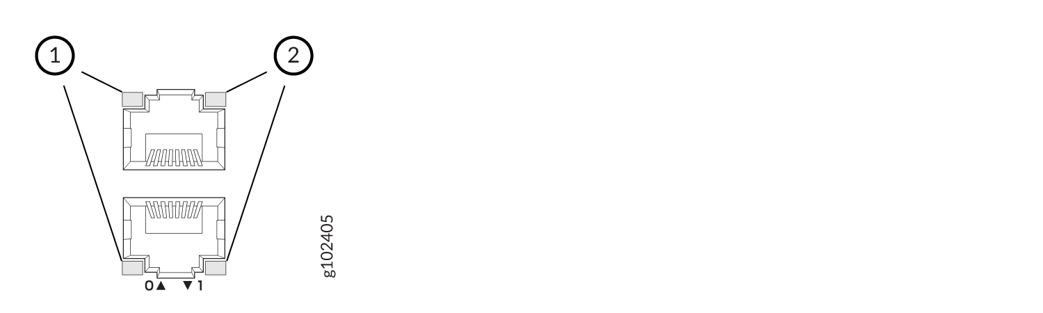
Management Port Status LEDs

| Callout | Label | State | Description |
|---|---|---|---|
|
1 |
Link (LED on the left) |
Solid green |
A link is established. |
|
Off |
No link established. |
||
|
2 |
Activity (LED on the right) |
Blinking green |
There is activity on the link. |
|
Off |
There is no link activity. |
RJ-45, SFP+, and SFP28 Network Port Status LEDs

| Callout 1 | Callout 2 | Description (for RJ-45, SFP+, and SFP28 ports) |
|---|---|---|
|
Status LED (Left LED) |
Link and Activity LED (Right LED) |
|
| Off | Off | Default (power on with or without Transceiver) |
| Solid green | Solid green | 25-Gbps link is up but there is no traffic on the port. |
| Blinking green | 25-Gbps link is up, and there is traffic on the port. | |
| Blinking green | Solid green | 10-Gbps link is up but there is no traffic on the port. |
| Blinking green | 10-Gbps link is up, and there is traffic on the port. | |
| Off | Solid green | 1-Gbps link is up but there is no traffic on the port. |
| Blinking green | 1-Gbps link is up, and there is traffic on the port. | |
| Off | Off | This indicates one of the following:
|
QSFP28 Network Port Status LEDs
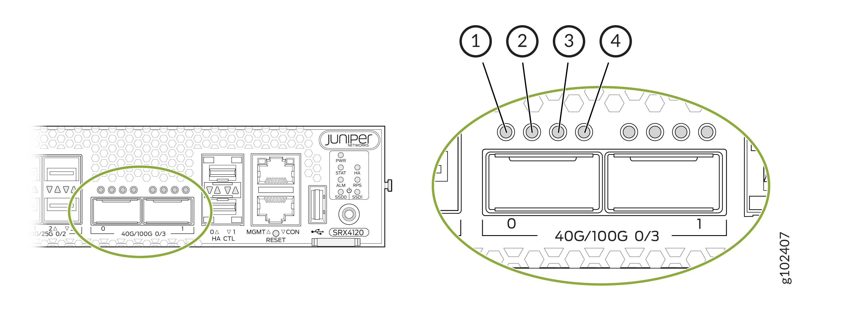
| LED | State | Description |
|---|---|---|
| 1 (non-channelized) | Solid green | 100-Gbps or 40-Gbps link is up but there is no traffic on the port. |
| Blinking green | 100-Gbps or 40-Gbps link is up, and there is traffic on the port. | |
| 1-4 (channelized) | Solid green | 4x25 Gbps or 4x10 Gbps link is up but there is no traffic on the port. |
| Blinking green | 4x25 Gbps or 4x10 Gbps link is up, and there is traffic on the port. | |
| 1-4 | Off | This indicates one of the following:
|
HA Port Status LEDs
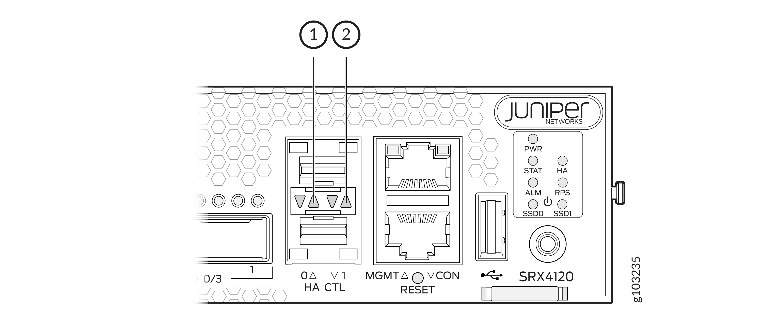
| Callout | Label | State | Description |
|---|---|---|---|
|
1 |
Link (LED on the left) |
Blinking green |
A link is established. |
|
Off |
No link established. |
||
|
2 |
Activity (LED on the right) |
Blinking green |
There is activity on the link. |
|
Off |
There is no link activity. |