Connecting the SRX380 to Power
Required Tools and Parts for Grounding the SRX380 Firewall
Table 1 lists the earthing terminal location, grounding cable requirements, grounding lug specifications, screws and washers required, and the screwdriver needed for connecting the device to earth ground. Before you begin connecting a device to earth ground, ensure that you have the parts and tools required for your device.
Grounding Cable Requirements |
Grounding Lug Specifications |
Screws and Washers |
Screwdriver |
|---|---|---|---|
10 AWG or as permitted by the local code |
Panduit LCD10-10AF-L or equivalent—not provided |
|
Phillips (+) number 2 |
Connecting the SRX380 Grounding Cable
To meet safety and electromagnetic interference (EMI) requirements and to ensure proper operation, you must connect the chassis to earth ground before you connect it to power.
Ensure that a licensed electrician has attached an appropriate grounding lug to the grounding cable you supply. Using a grounding cable with an incorrectly attached lug can damage the device.
You ground the services gateway by connecting a grounding cable to earth ground and then attaching the grounding cable to the chassis grounding point located on the rear of the device.
You must install the SRX380 in a restricted-access location and ensure that the chassis is always properly grounded. The SRX380 has a two-hole protective grounding terminal provided on the chassis. See Figure 1. Under all circumstances, use this grounding connection to ground the chassis. For AC-powered systems, you must also use the grounding wire in the AC power cord along with the two-hole grounding lug connection. This tested system meets or exceeds all applicable EMC regulatory requirements with the two-hole protective grounding terminal.
To ground the device:
- Place the grounding cable lug attached to the grounding
cable over the grounding point on the rear of the chassis.Figure 1: Connecting the Grounding Cable to the SRX380 Firewall
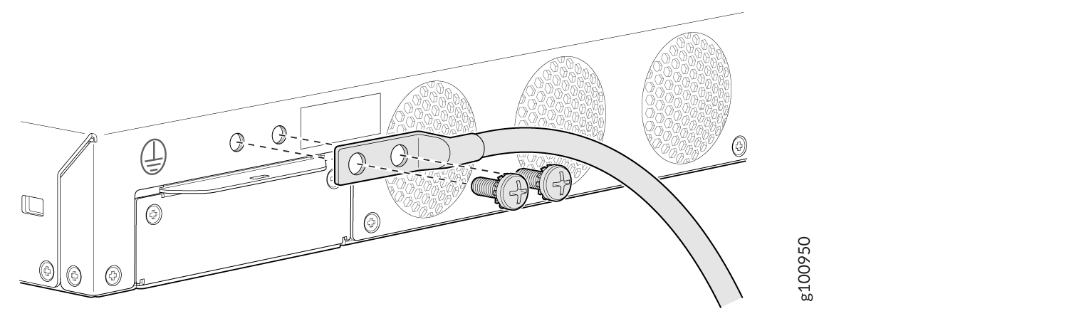
The device should be permanently connected to ground during operation.
Connecting the SRX380 Firewall to an AC Power Supply
Ensure that you have the following parts and tools available:
A power cord appropriate for your geographical location
A power cord retainer clip (provided with the device)
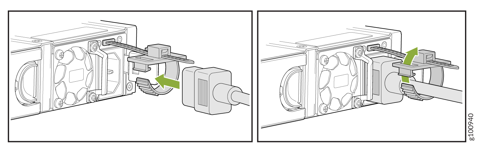
To connect AC power to the device:
- Slide the loop toward the power supply until it is snug
against the base of the coupler.Figure 2: Connecting an AC Power Cord
Powering Off the SRX380 Firewall
You can power off the services gateway in one of the following ways:
Graceful shutdown—Press and immediately release the Power button. The device begins gracefully shutting down the operating system and then powers itself off.
CAUTION:Use the graceful shutdown method to power off or reboot the services gateway.
Forced shutdown—Press the Power button and hold it down for 10 seconds. The device immediately powers itself off without shutting down the operating system.
CAUTION:Forced shutdown can result in data loss and corruption of the file system.
Use the forced shutdown method as a last resort to recover the services gateway if the services gateway operating system is not responding to the graceful shutdown method.
Do not press the Power button while the device is shutting down.
To remove power completely from the device, unplug the power cord or switch off the AC power source.
After powering off a power supply, wait at least 10 seconds before turning it back on. After powering on a power supply, wait at least 10 seconds before turning it off.
The Power button on the services gateway is a standby power switch, which will not turn off the input power to the services gateway.
When you are powering off the device, the CLI displays
the following message: Turning the system power off. You
can now safely remove the power cable to completely power off the
device.
You can use the request system reboot CLI command to schedule a reboot.