SRX340 Chassis
SRX340 Firewall Chassis Overview
The SRX340 Firewall chassis is a rigid sheet metal structure that houses all of the other services gateway components. The chassis measures 1.72 in. (4.36 cm) high, 17.36 in. (44.09 cm) wide, and 14.57 in. (37.01 cm) deep (from the front to the rear of the chassis). The chassis installs in standard 800–mm (or larger) enclosed cabinets, 19 in. equipment racks, or telecommunications open-frame racks.
Before removing or installing components of a functioning services gateway, attach an electrostatic discharge (ESD) strap to an ESD point and place the other end of the strap around your bare wrist. Failure to use an ESD strap could result in damage to the device.
The services gateway must be connected to earth ground during normal operation. The protective earthing terminal on the side of the chassis is provided to connect the services gateway to ground.
SRX340 Firewall Front Panel
Figure 1 shows the front panel of the SRX340 Firewall.
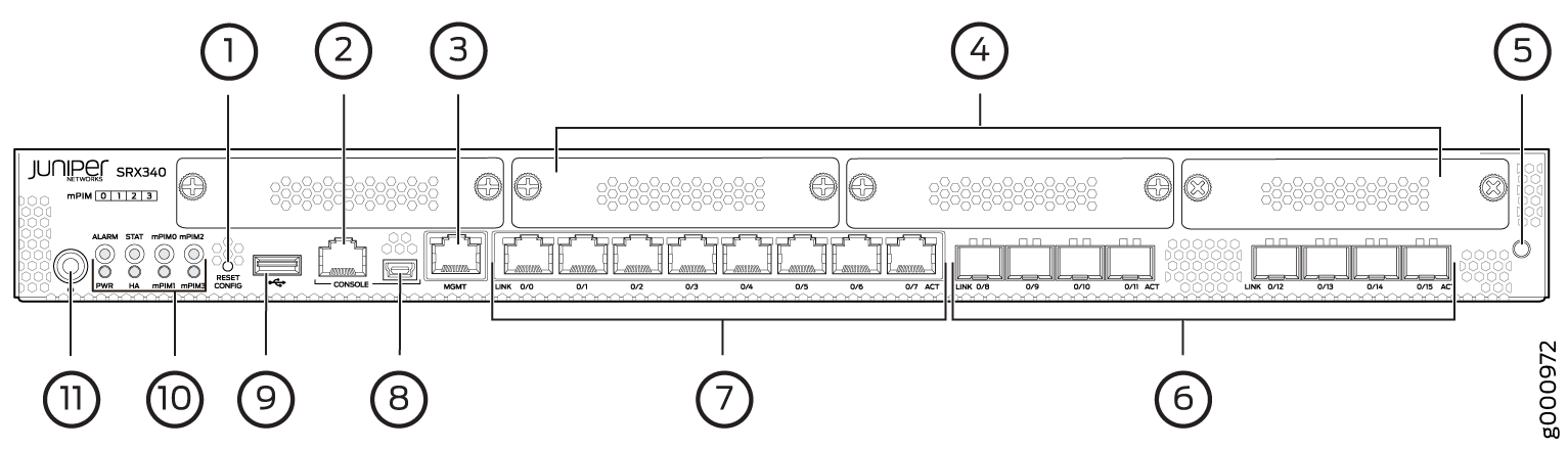
Table 1 provides details about the front panel components.
Callout |
Component |
Description |
|---|---|---|
1 |
Reset Config button |
Returns the services gateway to the rescue configuration or the factory-default configuration. |
2, 8 |
Console ports |
|
3 |
Management port |
Use the management (MGMT) port to connect to the device over the network. |
4 |
Mini-PIM slots |
Four slots for Mini-PIMs. Mini-PIMs can be used to provide LAN and WAN functionality along with connectivity to various media types. |
5 |
ESD point |
For personal safety, while working on the services gateway, use the ESD outlet to plug in an ESD grounding strap to prevent your body from sending static charges to the services gateway. |
6 |
1-GbE small form-factor pluggable (SFP) ports |
Eight 1-GbE MACsec-capable SFP ports for network traffic. |
7 |
1-GbE Ethernet ports |
Eight LAN ports (0/0 to 0/7), which are MACsec capable. The ports have the following characteristics:
The ports can be used to:
|
9 |
USB port |
The services gateway has one USB port that accepts a USB storage device. |
10 |
LEDs |
Indicate component and system status at a glance. |
11 |
Power button |
Use the Power button to power on or power off the services gateway. |
Figure 2 shows the LEDs on the front panel.
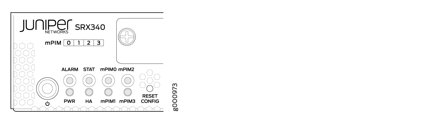
Table 2 lists the front panel LEDs.
Component |
Description |
|---|---|
ALARM |
|
STAT |
|
PWR |
|
HA |
|
mPIM0 , mPIM1, mPIM2, and mPIM3 |
|
Management Port LEDs
The management port has two LEDs that indicate link activity and status of the management port.
Table 3 describes the LEDs.
LED |
Description |
|---|---|
Link (LED on the left) |
|
Activity (LED on the right) |
|
Network Port LEDs
The SFP and Ethernet ports have two status LEDs, LINK and ACT, located above the port.
LED |
Description |
|---|---|
LINK (LED on the left) |
|
ACT (LED on the right) |
|
SRX340 Firewall Back Panel
Figure 3 shows the back panel of the SRX340 Firewall and Table 5 lists the components on the back panel.

Callout |
Component |
Description |
|---|---|---|
1 |
SSD slot |
SSD storage device slot for optional logging device. |
2 |
Fans |
Keeps all the services gateway components within the acceptable temperature range. |
3 |
Power supply input |
Connects the services gateway to the AC power supply. |
SRX340 Firewall Interface Modules Overview
Mini-Physical Interface Modules (Mini-PIMs) are field-replaceable network interface cards (NICs) supported on the SRX300 line of services gateways. You can easily insert or remove Mini-PIMs from the front slots of the services gateway chassis. The Mini-PIMs provide physical connections to a LAN or a WAN. The Mini-PIMs receive incoming packets from the network and transmit outgoing packets to the network. During this process, they perform framing and line-speed signaling for the medium type.
The Mini-PIMs are not hot-swappable. You must power off the services gateway before removing or installing Mini-PIMs.
The following Mini-PIMs are supported on the SRX340 Firewall:
1-Port Serial Mini-Physical Interface Module (SRX-MP-1SERIAL-R)
1-Port T1/E1 Mini-Physical Interface Module (SRX-MP-1T1E1-R)
1-Port VDSL2 (Annex A) Mini-Physical Interface Module (SRX-MP-1VDSL2-R)
LTE Mini-Physical Interface Module (SRX-MP-LTE-AE and SRX-MP-LTE-AA)
Wi-Fi Mini-Physical Interface Module (SRX-MP-WLAN-US, SRX-MP-WLAN-IL, and SRX-MP-WLAN-WW)
Gigabit-Backplane Physical Interface Modules (GPIMs) are not supported on the SRX340 Firewall.
For more information on the Mini-PIMs, see the SRX300 Series and SRX550 High Memory Gateway Interface Modules Reference.