ON THIS PAGE
SRX300 Series and SRX550 High Memory Services Gateway Interface Overview
SRX300 Series and SRX550 High Memory Services Gateway Mini-Physical Interface Modules Overview
Interfaces Port Naming Conventions for the SRX300 Series and SRX550 High Memory Services Gateways
SRX300 Series and SRX550 High Memory Services Gateway Interface Modules and Compatibility
MTU Default and Maximum Values for Physical Interface Modules
Power over Ethernet Support on SRX550 High Memory Services Gateway Interfaces
SRX300 Series and SRX550 High Memory Services Gateway Interfaces Power and Heat Requirements
SRX300 Series and SRX550M Interface Modules Support
SRX300 Series and SRX550 High Memory Services Gateway Interface Overview
Mini-Physical Interface Modules (Mini-PIMs) and Gigabit-Backplane Physical Interface Modules (GPIMs) are field-replaceable network interface cards (NICs), which provide physical connections to a LAN or a WAN. You can easily insert or remove Mini-PIMs and GPIMs from the front slots of the services gateway chassis. The Mini-PIMs and GPIMs receive incoming packets from the network and transmit outgoing packets to the network. During this process, they perform framing and line-speed signaling for the medium type.
The SRX300 Series Services Gateways support only Mini-PIMs. The SRX550 High Memory Services Gateway supports both Mini-PIMs and GPIMs.
SRX300 Series and SRX550 High Memory Services Gateway Mini-Physical Interface Modules Overview
Table 1 lists the supported Mini-PIMs and their model numbers.
Mini-PIMs |
Model Numbers |
|---|---|
Serial Mini-PIM |
SRX-MP-1Serial-R |
T1/E1 Mini-PIM |
SRX-MP-1T1E1-R |
VDSL2 Mini-PIM |
SRX-MP-1VDSL2-R |
LTE Mini-PIM |
SRX-MP-LTE-AE (for North America and the European Union) SRX-MP-LTE-AA (for Asia and Australia) |
Wi-Fi Mini-PIM |
SRX-MP-WLAN-US (for United States) SRX-MP-WLAN-IL (for Israel) SRX-MP-WLAN-WW (for other countries) |
The Mini-PIMs are field-replaceable. You can install a Mini-PIM in the Mini-PIM slot on the front panel of the services gateway chassis.
The Mini-PIMs are not hot-swappable. You must power off the services gateway before removing or installing Mini-PIMs.
SRX300 Series and SRX550 High Memory Services Gateway Gigabit-Backplane Physical Interface Modules Overview
A Gigabit-Backplane Physical Interface Module (GPIM) is a network interface card (NIC) that installs in the front slots of the SRX550 High Memory Services Gateway to provide physical connections to a LAN or a WAN. The GPIM receives incoming packets from a network and transmits outgoing packets to a network. These modules complement the onboard Ethernet interfaces to extend the types and port counts of network connections for the LAN or WAN.
Interface module terminology:
GPIM—Can be installed in one of the single-high, single-wide GPIM front slots of the SRX550 High Memory Services Gateway that have Gigabit connectivity to the system backplane.
XPIM—Can be installed only in the 10-Gigabit GPIM slot 3 or in the 20-Gigabit GPIM slot 6 on the front panel of the SRX550 High Memory Services Gateway.
The GPIMs can have one of the following configurations:
Single-high, single-wide LAN switch GPIM that uses one slot
Double-high, single-wide LAN switch GPIM that uses two standard slots vertically
Note:GPIMs are not supported on the SRX300 Series devices.
Table 2 lists the GPIMs and XPIMs and their respective model numbers.
GPIM or XPIM |
Model Number |
|---|---|
8-Port Gigabit Ethernet SFP XPIM |
SRX-GP-8SFP |
16-Port Gigabit Ethernet XPIM (with PoE) |
SRX-GP-16GE-POE |
Dual CT1/E1 GPIM |
SRX-GP-DUAL-T1-E1 |
Quad CT1/E1 GPIM |
SRX-GP-QUAD-T1-E1 |
1-Port Clear Channel DS3/E3 GPIM |
SRX-GP-1DS3-E3 |
Figure 1 shows how the slots on the front panel of the SRX550 High Memory Services Gateway are numbered. Slots 1 and 2 are for Mini-PIMs, and slots 3 through 8 are for GPIMs.
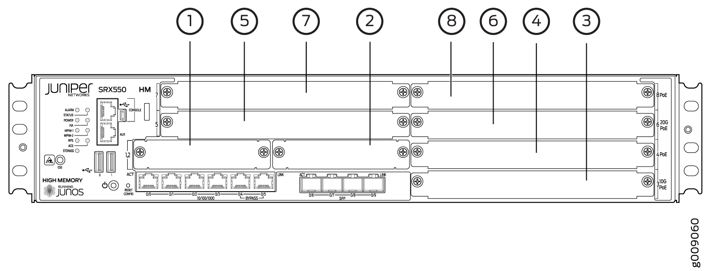
Figure 2 and Figure 3 show the form factors for the services gateway GPIMs.
Interfaces Port Naming Conventions for the SRX300 Series and SRX550 High Memory Services Gateways
When configuring a port on a Mini-Physical Interface Module (Mini-PIM) or Gigabit-Backplane Physical Interface Module (GPIM), you must know the slot and port number assigned to the Mini-PIM or GPIM. The slot number identifies the slot on the services gateway in which you insert the Mini-PIM or GPIM, and is typically named 1, 2, 3, and so on. The port number is the port on the Mini-PIM or GPIM that is being configured.
The name of each network interface has the following format to identify the physical device that corresponds to a single physical network connector:
type-slot/pim/port
For SRX Series Firewalls, pim equals 0 for the port-naming convention.
For the LTE Mini-PIM, port equals 0.
Table 3 lists the typical interface types and interface numbers.
Interface Type |
Interface Number Example |
|---|---|
T1 |
t1–1/0/0 |
E1 |
e1–1/0/0 |
Serial |
se–1/0/0 |
VDSL2 |
pt–1/0/0 |
LTE |
cl–1/0/0 Note:
The LTE Mini-PIM can be installed in any one of the Mini-PIM slots on the SRX320, SRX340, SRX345, SRX380, and SRX550 HM Services Gateways. |
Wi-Fi Mini-PIM |
wl–1/0/0 Note:
The Wi-Fi Mini-PIM can be installed in any one of the Mini-PIM slots on the SRX320, SRX340, SRX345, SRX380, and SRX550 HM Services Gateways. |
8-Port Gigabit Ethernet small form-factor pluggable (SFP) XPIM |
ge–3/0/0 through ge–3/0/7 Note:
The SRX550 High Memory Services Gateway has high gigabit and non-high gigabit slots.
|
16-Port Gigabit Ethernet XPIM |
Note:
When installing the 16–Port Gigabit Ethernet XPIM, which uses 2 slots, you must install it in the 10–Gigabit or 20–Gigabit GPIM slots:
|
Dual CT1/E1 GPIM |
ct1–1/0/0 ce1–1/0/0 |
Quad CT1/E1 GPIM |
ct1–1/0/0 ce1–1/0/0 |
DS3/E3 GPIM |
t3-1/0/0 e3-2/0/0 |
SRX300 Series and SRX550 High Memory Services Gateway Interface Modules and Compatibility
Table 4 shows the types of Mini-Physical Interface Modules (Mini-PIMs) with the SRX Series Firewalls and the Junos OS releases that support them.
Name |
Supported Platforms and the First Junos OS Release Supported |
|||||
|---|---|---|---|---|---|---|
SRX300 |
SRX320 |
SRX340 |
SRX345 |
SRX380 |
SRX550 High Memory |
|
Serial |
Not supported |
Junos OS Release 15.1X49–D35 |
Junos OS Release 15.1X49–D35 |
Junos OS Release 15.1X49–D35 |
Junos OS Release 20.1R1 |
Junos OS Release 15.1X49–D30 |
T1/E1 |
Not supported |
Junos OS Release 15.1X49–D35 |
Junos OS Release 15.1X49–D35 |
Junos OS Release 15.1X49–D35 |
Junos OS Release 20.1R1 |
Junos OS Release 15.1X49–D30 |
VDSL2 |
Not supported |
Junos OS Release 15.1X49–D35 |
Junos OS Release 15.1X49–D35 |
Junos OS Release 15.1X49–D35 |
Junos OS Release 20.1R1 |
Junos OS Release 15.1X49–D30 |
LTE |
Not supported |
Junos OS Release 15.1X49–D100 |
Junos OS Release 15.1X49–D100 |
Junos OS Release 15.1X49–D100 |
Junos OS Release 20.1R1 |
Junos OS Release 15.1X49–D100 |
Wi-Fi |
Not supported |
Junos OS Release 19.4R1 |
Junos OS Release 19.4R1 |
Junos OS Release 19.4R1 |
Junos OS Release 20.1R1 |
Junos OS Release 19.4R1 |
Table 5 shows the type of Gigabit-Backplane Physical Interface Modules (XPIMs), along with the SRX Series Firewalls and the Junos OS releases that support them.
Type |
Name |
First Junos OS Release |
|
|---|---|---|---|
SRX300 Series Services Gateways |
SRX550 High Memory |
||
XPIMs (10 Gigabit Ethernet GPIM) |
8-Port Gigabit Ethernet SFP |
Not supported |
Junos OS Release 15.1X49–D30 |
16-Port Gigabit Ethernet |
Not supported |
Junos OS Release 15.1X49–D30 |
|
|
GPIMs |
Dual CT1/E1 GPIM |
Not supported |
Junos OS Release 15.1X49–D30 |
Quad CT1/E1 GPIM |
Not supported |
Junos OS Release 15.1X49–D30 |
|
DS3/E3 GPIM |
Not supported |
Junos OS Release 15.1X49–D30 |
|
MTU Default and Maximum Values for Physical Interface Modules
Table 6 defines the terms that are used in the context of maximum transmission unit (MTU).
Term |
Definition |
|---|---|
Physical Interface MTU–Default |
Default value of the MTU at the physical interface. The
maximum value of the MTU at the physical interface includes the protocol
overhead. You can configure the default MTU value at the physical
interface by using the following command:set interface |
Logical Interface MTU–Default |
Default value of the MTU at the logical interface. The
default value is configured at the family level and does not include
the protocol overhead. You can configure the default MTU value for
each logical unit at the logical interface by using the following
command:set interface |
Maximum MTU |
Maximum MTU is the size, measured in bytes, of the largest physical packet that a network can transmit. Any message larger than the MTU is divided into smaller packets before it is sent to its final destination. |
Table 7 lists the MTU values for the SRX300 Series and SRX550 High Memory Services Gateway Physical Interface Modules (PIMs).
PIM |
Physical Interface MTU (Bytes)–Default |
Logical Interface MTU (Bytes)–Default |
Maximum MTU (Bytes) |
|---|---|---|---|
Serial Mini-PIM |
1504 |
1500 |
2000 |
T1/E1 Mini-PIM |
1504 |
1500 |
2000 |
8–Port Gigabit Ethernet small form–factor pluggable (SFP) XPIM |
1514 |
1500 |
9192 |
16–Port Gigabit Ethernet XPIM |
1514 |
1500 |
9192 |
Dual CT1/E1 GPIM |
1504 |
1500 |
9000 |
Quad CT1/E1 GPIM |
1504 |
1500 |
9000 |
1-Port Clear Channel DS3/ES3 GPIM |
1504 |
1500 |
9192 |
The LTE Mini-PIM uses the MTU value reported by the modem.
Table 8 lists maximum transmission unit (MTU) values for VDSL- Mini-PIM AT mode (Encapsulation).
Mini-PIM |
Physical Interface MTU (Bytes)–Default |
Logical Interface MTU (Bytes)–Default |
Maximum MTU (Bytes) |
|---|---|---|---|
VDSL- Mini-PIM AT mode (Encapsulation) |
|||
atm-snap |
1514 |
1506 |
1514 |
atm-vcmux |
1514 |
1514 |
1514 |
atm-nlpid |
1514 |
1510 |
1514 |
atm-cisco-nlpid |
1514 |
1512 |
1514 |
ether-over-atm-llc |
1514 |
1490 |
1524 |
atm-ppp-llc |
1514 |
1508 |
1514 |
atm-ppp-vcmux |
1514 |
1512 |
1514 |
atm-mlppp-llc |
1514 |
1500 |
1514 |
ppp-over-ether-over-atm-llc |
1514 |
1482 |
1514 |
VDSL- Mini-PIM PT mode |
1514 |
1500 |
1514 |
Power over Ethernet Support on SRX550 High Memory Services Gateway Interfaces
Power over Ethernet (PoE) supports the implementation of the IEEE 802.3 af and IEEE 802.3 at standards, which allow both data and electric power to pass over a copper Ethernet LAN cable.
The PoE ports supply electric power over the same ports that are used for connecting network devices. PoE ports allow you to plug in devices that require both network connectivity and electric power, such as voice over IP (VoIP), IP phones, and wireless access points.
The PoE ports for the SRX550 High Memory Services Gateway reside on the individual XPIMs. The SRX550 High Memory Services Gateway supports the 16-Port Gigabit Ethernet XPIM with PoE.
The active Services and Routing Engine manages the overall system PoE power. You can configure the services gateway to act as power sourcing equipment to supply the power to the GPIMs connected on the designated PoE ports.
Table 9 lists the PoE specifications for the SRX550 High Memory Services Gateway.
Power Management Schemes |
SRX550 High Memory Services Gateway |
|---|---|
Supported standards |
|
Supported slots/ports |
PoE is supported on the front panel slots 3,4,6, and 8. |
Total PoE power sourcing capacity |
The 645 W AC and 645 W DC power supplies support the following capacities:
|
Per-port power limit |
31.2 W |
Power management modes |
|
SRX300 Series and SRX550 High Memory Services Gateway Interfaces Power and Heat Requirements
Table 10 shows the power consumption values of each Physical Interface Module (PIM).
PIM Model |
Power Consumption (Watts) |
|---|---|
Serial Mini-PIM |
4.29 |
T1/E1 Mini-PIM |
1.92 |
VDSL2 Mini-PIM |
9.80 |
LTE Mini-PIM |
4.8 |
Wi-Fi Mini-PIM |
7.12 |
8-Port Gigabit Ethernet SFP XPIM |
22 |
16-Port Gigabit Ethernet XPIM |
40 (without PoE) |
Dual CT1/E1 GPIM |
16.81 |
Quad CT1/E1 GPIM |
16.81 |
1-Port Clear Channel DS3/E3 GPIM |
22.89 |