Maintaining the SRX1500 Power System
Maintaining the SRX1500 Firewall Power Supply
To maintain the power supplies of the services gateway:
Make sure that all power and grounding cables are arranged so that they do not obstruct access to other services gateway components.
Routinely check the PWR LED on the front panel. If this LED is solid green, the power supplies are functioning normally.
Periodically inspect the site to ensure that the grounding and power cables connected to the services gateway are securely in place and that there is no moisture accumulating near the services gateway.
Required Tools and Parts for Replacing the SRX1500 Firewall Components
The following tools and parts are required to replace hardware components.
3/8 in. nut driver or pliers
Blank panels (if component is not reinstalled)
Electrostatic bag or antistatic mat
Electrostatic discharge (ESD) grounding wrist strap
Flat-blade (–) screwdriver
Phillips (+) screwdrivers, numbers 1 and 2
Wire cutters
Replacing an AC Power Supply on the SRX1500 Firewall
- Disconnecting an AC Power Cord from the SRX1500 Firewall
- Removing an AC Power Supply from the SRX1500 Firewall
- Installing an AC Power Supply on the SRX1500 Services Gateway
Disconnecting an AC Power Cord from the SRX1500 Firewall
Before working on an AC-powered device or near power supplies, unplug the power cord.
To disconnect the AC power cord:
- Unplug the power cord from the power source receptacle.
- Attach an electrostatic discharge (ESD) grounding strap to your bare wrist and connect the strap to one of the ESD points on the chassis. For more information about ESD, see Prevention of Electrostatic Discharge Damage.
- Unplug the power cord from the appliance inlet on the power supply.
Removing an AC Power Supply from the SRX1500 Firewall
Up to two power supplies can be located at the rear of the chassis on the right side. Each AC power supply weighs 2.20 lb (1 kg).
Do not leave a power supply slot empty for more than 30 minutes while the services gateway is operational. For proper airflow, the power supply must remain in the chassis, or a blank panel must be used in the empty slot.
After powering off a power supply, wait at least 60 seconds before turning it back on.
To remove an AC power supply:
- Switch off the dedicated facility circuit breaker for the power supply, and remove the power cord from the AC power source. Follow the electrostatic discharge (ESD) and disconnection instructions for your site.
- Attach an ESD grounding strap to your bare wrist and connect the strap to one of the ESD points on the chassis. For more information about ESD, see Prevention of Electrostatic Discharge Damage.
- Remove the power cord from the power supply.
- Press the latch to the left of the power outlet (see Figure 1).
- Pull the power supply straight out of the chassis.
Installing an AC Power Supply on the SRX1500 Services Gateway
To install an AC power supply:
- Using both hands, slide the power supply straight into
the chassis until the power supply is fully seated in the chassis
slot. The power supply faceplate should be flush with any adjacent
power supply faceplate (see Figure 2).Figure 2: Installing an AC Power Supply on the SRX1500 Services Gateway
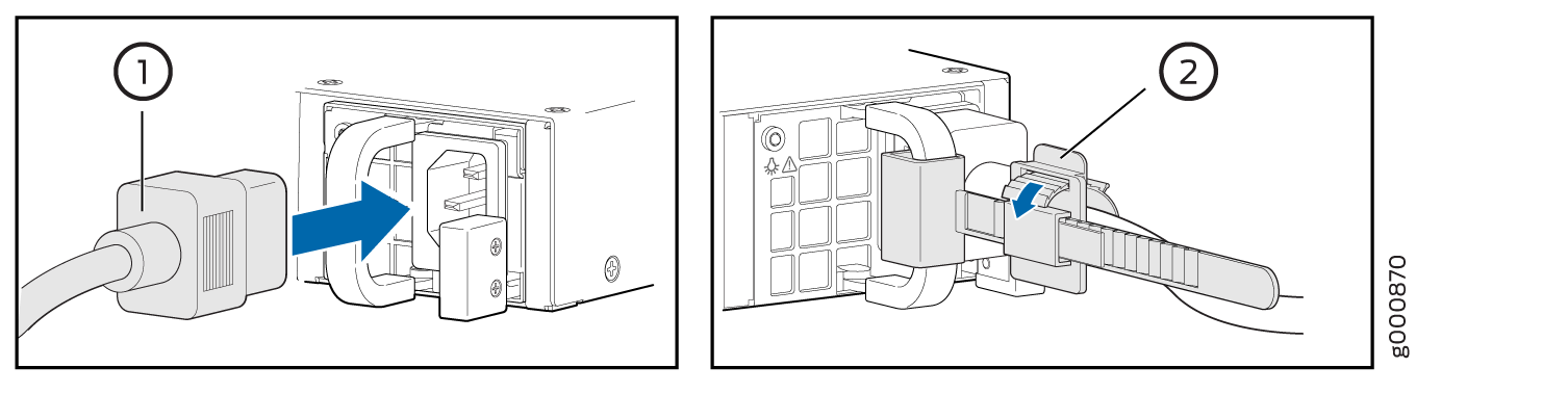
- Attach the power cord to the power supply. Use a power
cord retainer to hold the power cord in place.Figure 3: Connecting the AC Power Cord on the SRX1500 Services Gateway
If more than one power supply is being installed, ensure the following:
Connect power cords to both the power supplies.
Connect each power supply to a DC power feed.
If both power supplies are plugged in and receiving power, the RPS LED glows solid green.
Replacing a DC Power Supply on the SRX1500 Firewall
- Removing a DC Power Supply Cable from the SRX1500 Firewall
- Removing a DC Power Supply on the SRX1500 Firewall
- Installing a DC Power Supply on the SRX1500 Services Gateway
Removing a DC Power Supply Cable from the SRX1500 Firewall
To remove a power supply cable connected to a DC power supply:
- Attach an electrostatic discharge (ESD) grounding strap to your bare wrist and connect the strap to an approved site ESD grounding point. For more information about ESD, see Prevention of Electrostatic Discharge Damage.
- Switch off the external circuit breakers for all the cables attached to the power supply. Make sure that the voltage across the DC power source cable leads is 0 V and that there is no chance that the cables might become active during the removal process.
- Remove the power cable from the DC power source.
- Attach an ESD grounding strap to your bare wrist and connect the strap to one of the ESD points on the chassis. For more information about ESD, see Prevention of Electrostatic Discharge Damage.
- Make sure the cable is not touching or in the way of any services gateway components and that it does not drape where people could trip on it.
- Remove the clear plastic cover protecting the terminal studs on the faceplate.
- Attach the power cable to the DC power source.
- Verify that the DC source power cabling is correct. If the power cable is correctly installed and the power supply is functioning normally, the POWER LED on the front panel glows solid green.
Removing a DC Power Supply on the SRX1500 Firewall
Up to two power supplies can be located at the rear of the chassis on the right side. Each DC power supply weighs approximately 2.20 lbs (1 kg).
Do not leave a power supply slot empty for more than 30 minutes while the services gateway is operational. For proper airflow, the power supply must remain in the chassis, or a blank panel must be used in the empty slot.
After powering off a power supply, wait at least 60 seconds before turning it back on.
To remove a DC power supply:
- Switch off the dedicated facility circuit breaker for the power supply. Follow the electrostatic discharge (ESD) and disconnection instructions for your site.
- Make sure that the voltage across the DC power source cable leads is 0 V and that there is no chance that the cables might become active during the removal process.
- Attach an ESD grounding strap to your bare wrist and connect the strap to one of the ESD points on the chassis. For more information about ESD, see Prevention of Electrostatic Discharge Damage.
- Remove the clear plastic cover protecting the terminal studs on the faceplate.
- Remove the screws and washers from the terminals. Use a number 2 Phillips screwdriver to loosen and remove the screws.
- Remove the cable lugs from the terminal studs.
- Carefully move the power cables out of the way.
- Push the Tab latch on the right edge of the power supply to the left.
- Pull the power supply straight out of the chassis.
Installing a DC Power Supply on the SRX1500 Services Gateway
To install a DC power supply:
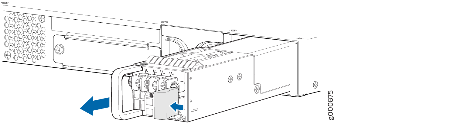
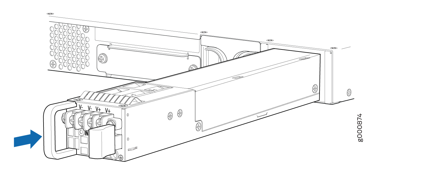
- Orient the power supply so that the locking lever is on
the left as shown in Figure 5.Figure 5: Installing a DC Power Supply on an SRX1500 Services Gateway
- Secure each power cable lug to the terminal studs, first
with the square washer, then with the screw. Apply between 23 lb-in.
(2.6 Nm) and 25 lb-in. (2.8 Nm) of torque to each screw.
- Attach the positive (+) DC source power cable lug to the RTN (return) terminal.
- Attach the negative (–) DC source power cable lug to the –48V (input) terminal.
Figure 6: Securing the Power Cables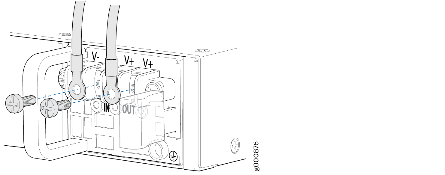
If more than one power supply is being installed, turn on all power supplies at the same time.
If both power supplies are plugged in and receiving AC power, the RPS LED glows solid green.