NFX350 Front Panel and Rear Panel
Figure 1: Front Panel Components
of NFX350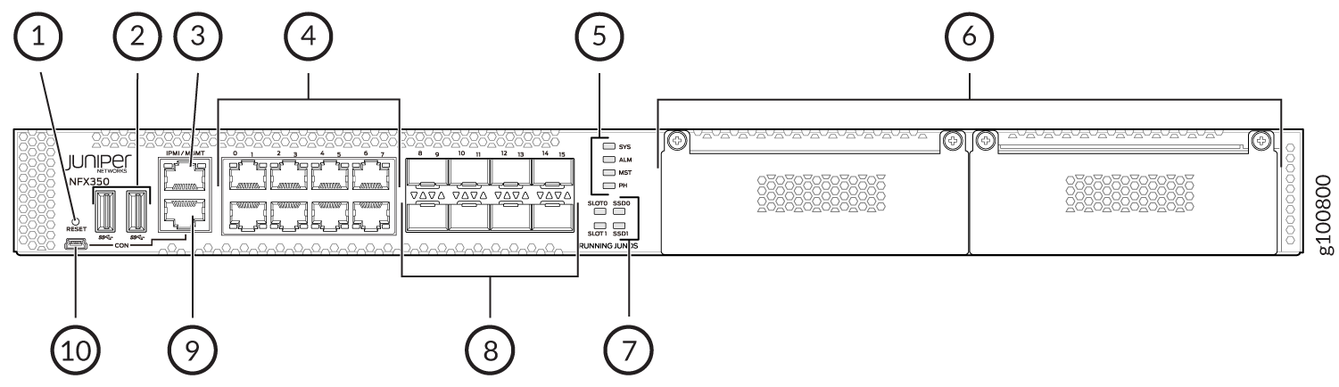
1 — Reset button | 6 — Two expansion slots |
2 — Two USB 3.0 ports | 7 — SSD and slot status LEDs |
3 — One 10/100/ 1000BASE-T RJ-45 management port | 8 — Eight 1-Gigabit Ethernet/10-Gigabit Ethernet SFP+ WAN ports |
4 — Eight 10/100/ 1000BASE-T RJ-45 LAN ports | 9 — RJ-45 console port |
5 — System status LEDs | 10 — Mini-USB console port |
Figure 2: Rear Panel Components
of NFX350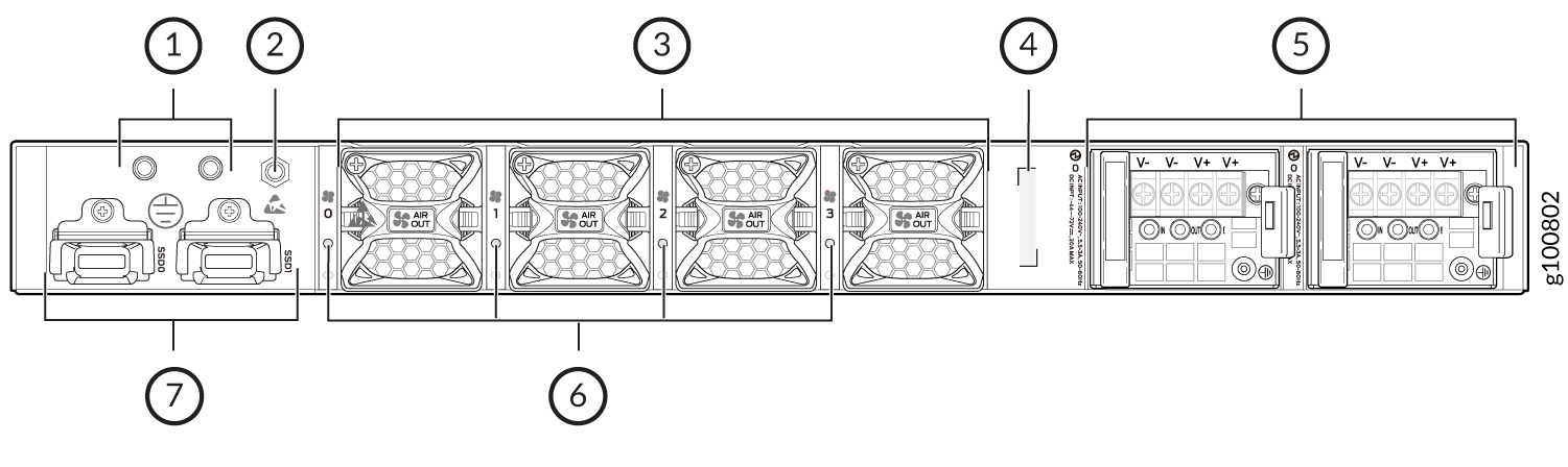
1 — Grounding point | 5 — Two power supply units |
2 — Electrostatic discharge (ESD) point | 6 — Fan status LEDs |
3 — Four fans | 7 — Two SSD trays |
4 — CLEI code |