Step 1: Prepare the Site for Installing an ACX5400 Router
Rack Requirements for ACX5400 Routers
The ACX5400 routers are designed to be installed on four-post racks.
Table 1 provides the rack requirements and specifications for ACX5400 routers.
Rack Requirement |
Guidelines |
|---|---|
Rack type |
Use a four-post rack that provides bracket holes or hole patterns spaced at 1-U increments (1.75 in. or 4.45 cm) and that the rack meets the size and strength requirements to support the weight. A U is the standard rack unit defined in Cabinets, Racks, Panels, and Associated Equipment (document number EIA-310–D) published by the Electronics Industry Association. |
Mounting bracket hole spacing |
Ensure that the holes in the mounting brackets are spaced at 1 U (1.75 in. or 4.45 cm) so that the router can be mounted in any rack that provides holes spaced at that distance. |
Rack size and strength |
|
Rack connection to building structure |
|
Router Clearance Requirements
For the cooling system to function properly, the airflow around the chassis must be unrestricted. You must allow sufficient clearance around the installed chassis for cooling and maintenance.
If you are mounting an ACX5400 in a rack with other equipment, ensure that the exhaust from the other equipment does not blow into the intake vents of the ACX5400 chassis.
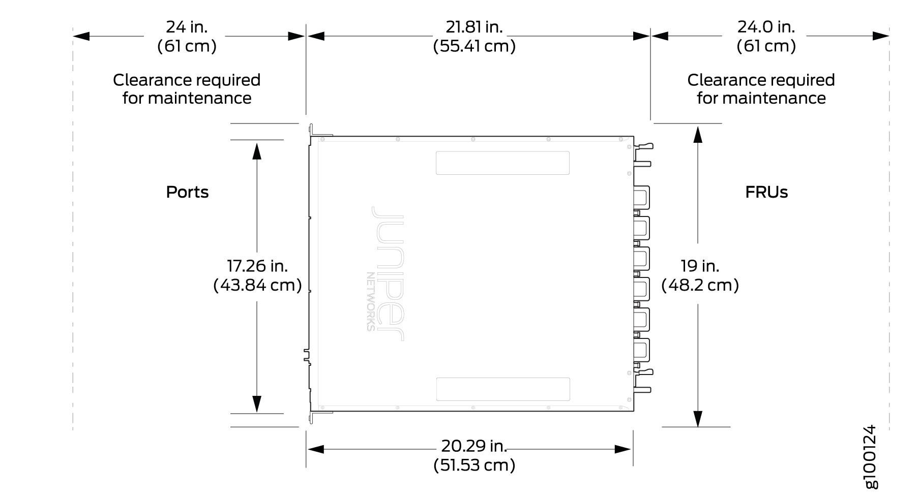
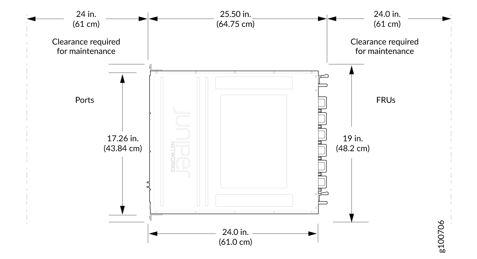
For service personnel to remove and install hardware components, and to accommodate the interface and power cable bend radius, there must be adequate space at the front and rear of the router. Allow at least 24 in. (61 cm) of space both at the front and the rear of the router. See Figure 1 for clearance requirements in ACX5448 and ACX5448-D routers and Figure 2 for clearance requirements in ACX5448-M routers.


Router Cooling and Airflow Requirements
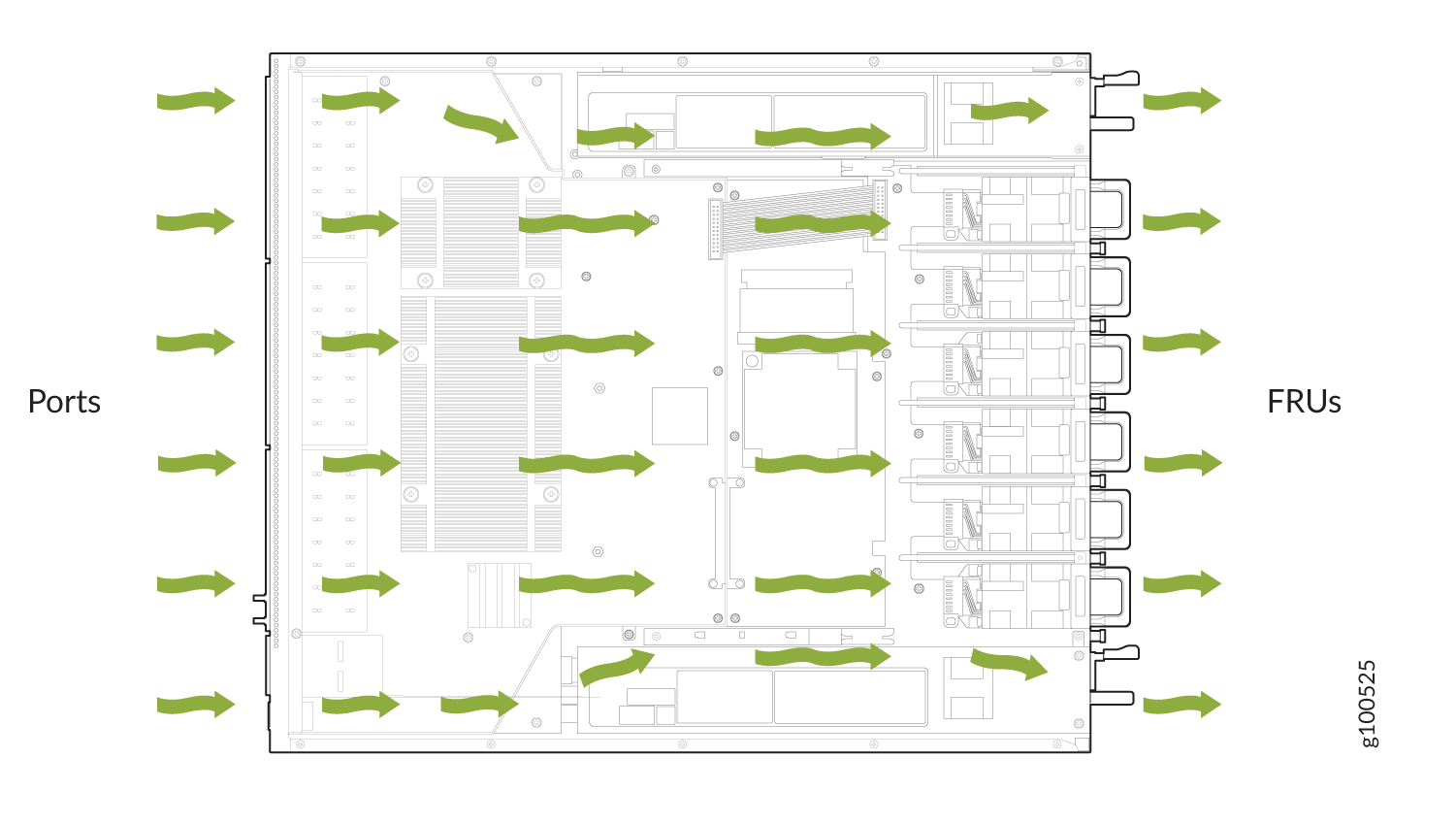
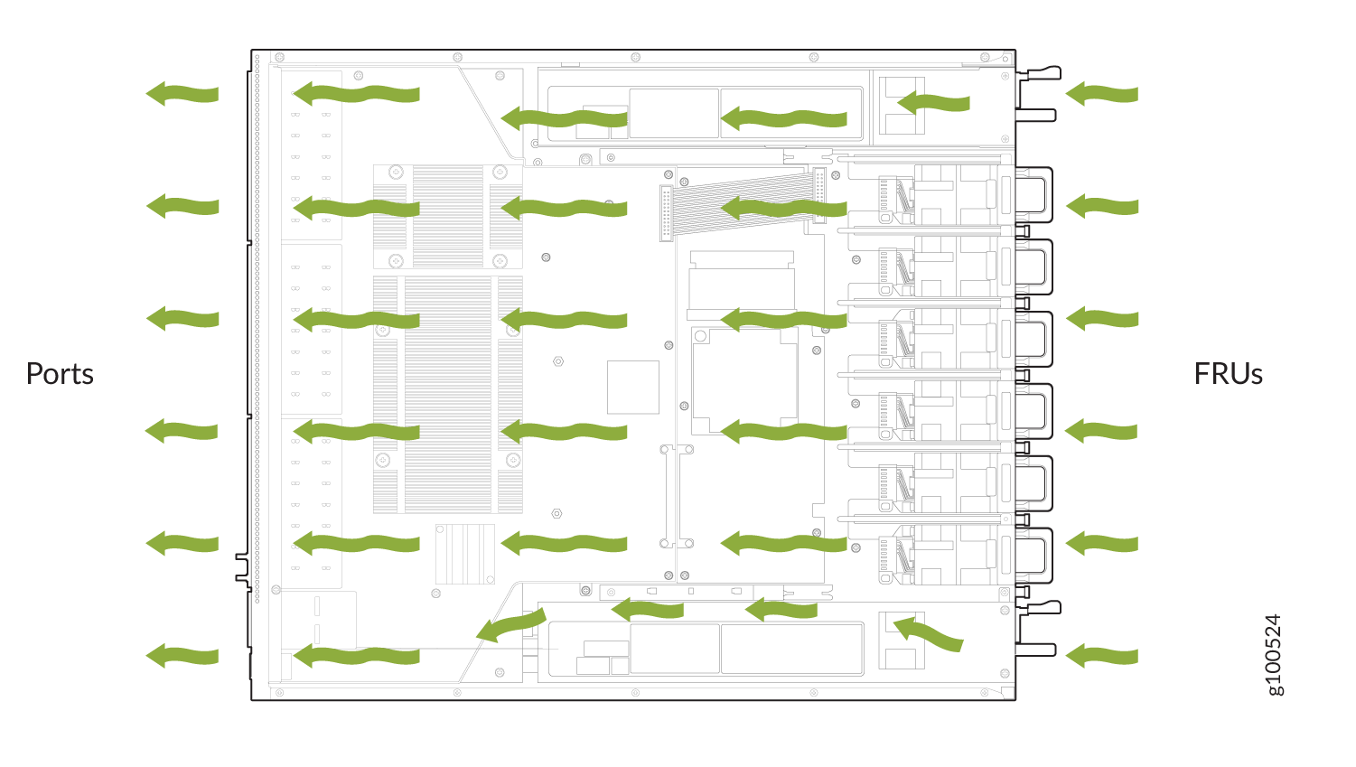
The ACX5400 routers are available with either front-to-back airflow (airflow out, ports-to-FRUs, or AFO), or back-to-front airflow (airflow in, FRUs-to-ports, or AFI). In AFO models, the air is pulled through the front of the chassis toward the fan modules, from where it is exhausted out of the chassis. In AFI models, the air is pulled through the fan modules and toward the front of the chassis, from where it is exhausted out of the chassis. The fan modules and the power supply modules (PSMs) are available in both AFO and AFI variants. Figure 3 and Figure 4 show the airflow through the two router models.
For the cooling system to function properly, the airflow around the chassis must be unrestricted.
The PSMs are self-cooling and are located in the rear of the router. The exhaust for the PSMs are also located on the rear of the chassis.
The rack or cabinet must have an adequate supply of cooling air.


Do not mix different types of airflow modules in the same chassis. The fan modules and PSMs must be of the same airflow type (AFO or AFI).
Tools Required to Prepare the ACX5400 Router for Installation
ESD grounding strap (not provided).
One pair of rear-mounting blades (provided). These mounting blades support the rear of the chassis and must be installed.
One pair of front-mounting rails, with mounting brackets attached at one end (provided). The mounting rails accommodate the mounting blades that slide into the rails.
Twelve screws to secure the mounting rails to the chassis (provided).
Eight screws to secure the chassis and mounting blades to the rack (not provided).
Appropriate screwdriver for the mounting screws (not provided).
Two power cords with plugs appropriate for your geographical location (provided).
-
RJ-45 cable and RJ-45 to DB-9 serial port adapter (not provided).
Note:We no longer include the RJ-45 console cable with the DB-9 adapter as part of the device package. If the console cable and adapter are not included in your device package, or if you need a different type of adapter, you can order the following separately:
-
RJ-45 to DB-9 adapter (JNP-CBL-RJ45-DB9)
-
RJ-45 to DB-9 adapter (JNP-CBL-RJ45-DB9)
-
RJ-45 to USB-C adapter (JNP-CBL-RJ45-USBC)
If you want to use RJ-45 to USB-A or RJ-45 to USB-C adapter you must have X64 (64-Bit) Virtual COM port (VCP) driver installed on your PC. See, https://ftdichip.com/drivers/vcp-drivers/ to download the driver.
-
Management host, such as a PC laptop, with a serial port (not provided).
