Install and Remove QFX5700 Line Card Components
Line cards on the QFX5700 are field-replaceable units (FRUs) that can be installed in any of the line-card slots on the front of the chassis. The line cards are hot-insertable and hot-removable: you can remove and replace them without powering off the switch or disrupting switch functions.
How to Handle and Store QFX5700 Line Cards
The QFX5700 line cards have fragile components. To avoid damaging the line cards, be sure you follow safe handling practices.
How to Hold QFX5700 Line Cards
Pay proper attention to the way you hold the line cards. Line cards are installed horizontally, and it is best to hold them by the sides of the units when they are not in the chassis.
When you walk with a line card in hand:
How to Store a Line Card
You must store line cards either in the chassis or in a spare shipping container, horizontally and sheet-metal side down. Don’t stack these units on top of one another or on top of any other component. Place each unit separately in an antistatic bag or on an antistatic mat placed on a flat, stable surface.
Because these units are heavy and because antistatic bags are fragile, inserting the line card into the bag is best done by two people.
To insert a line card into an antistatic bag:
- Hold the unit horizontally with the faceplate toward you.
- Slide the opening of the bag over the connector edge.
If you must insert the line card into a bag by yourself:
Lay the unit horizontally on an antistatic mat that is on a flat, stable surface with the sheet-metal side down.
Orient the unit with the faceplate toward you.
Carefully insert the connector edge into the opening of the bag and pull the bag toward you to cover the unit.
Install a QFX5700 RCB Card
Before you install a line card in the switch chassis:
Ensure that you have taken the necessary precautions to prevent electrostatic discharge (ESD) damage. See Prevention of Electrostatic Discharge Damage.
Ensure that you know how to handle and store the line card.
Inspect the connector edge of the line card for physical damage. Installing a damaged line card might damage the switch.
Ensure that the switch has sufficient power to power the line card while maintaining its n+1 power redundancy. To determine whether the switch has enough power available for the line card, use the
show chassis power-budget-statisticscommand.Ensure that you have the following parts and tools available to install a line card in the switch:
ESD grounding strap
Phillips (+) screwdriver, number 2
To install a line card in the switch chassis:
You need to install the RCB in an “upside-down” position.
- Wrap and fasten one end of the ESD grounding strap around
your bare wrist and connect the other end of the strap to one of the
ESD points on the chassis. An ESD point is located above the status
LED panel on the front of the switch chassis. See Figure 1.Figure 1: ESD Point on the Front of QFX5700
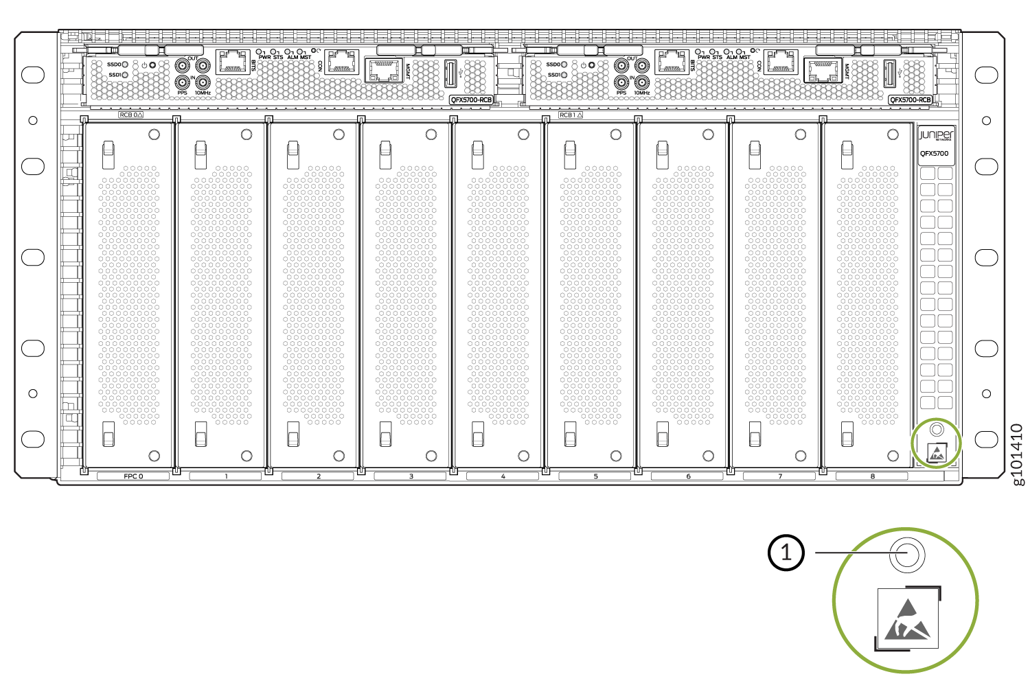 1—ESD point
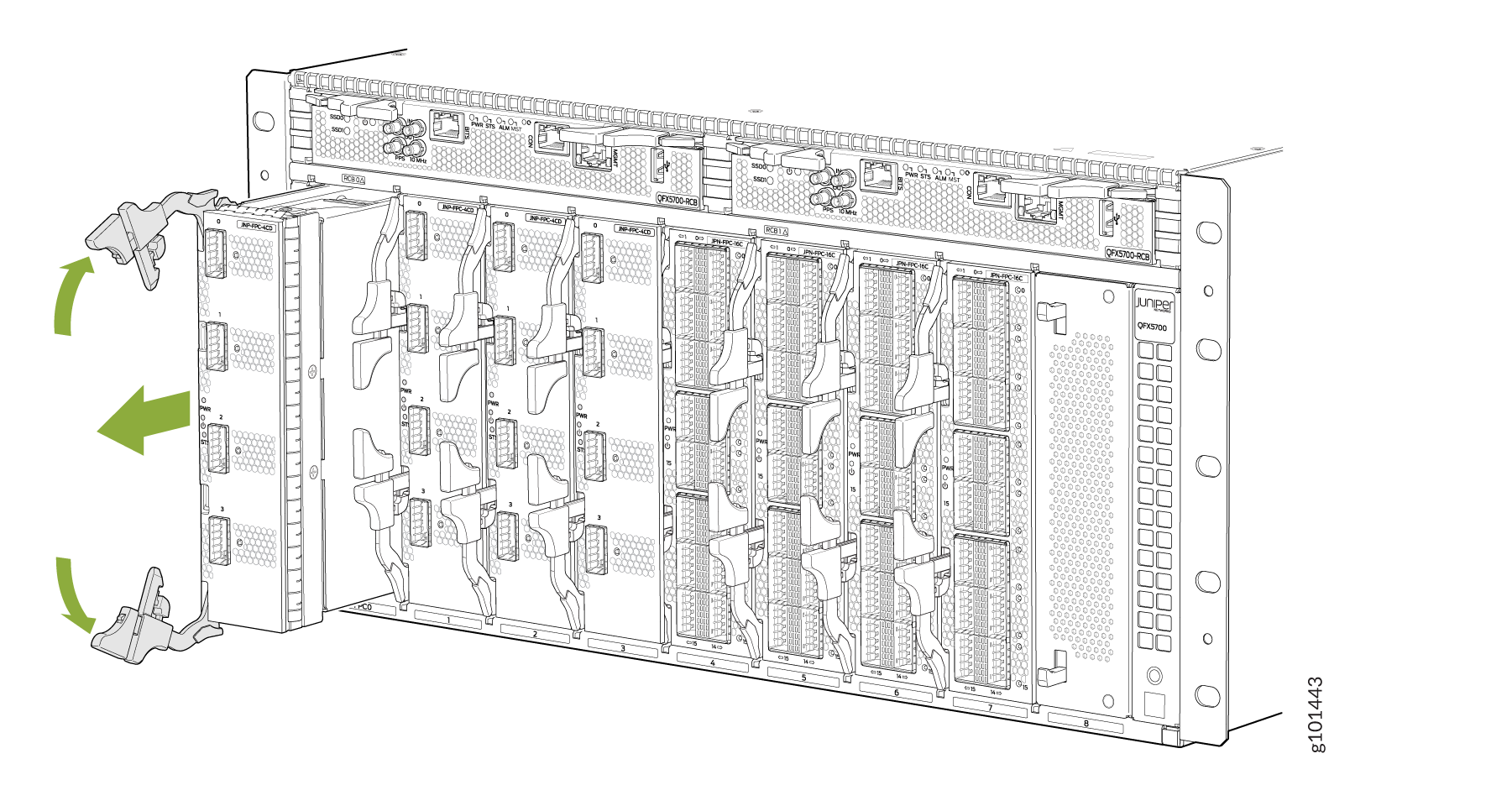
 - See Figure 2.Figure 2: Remove the RCB
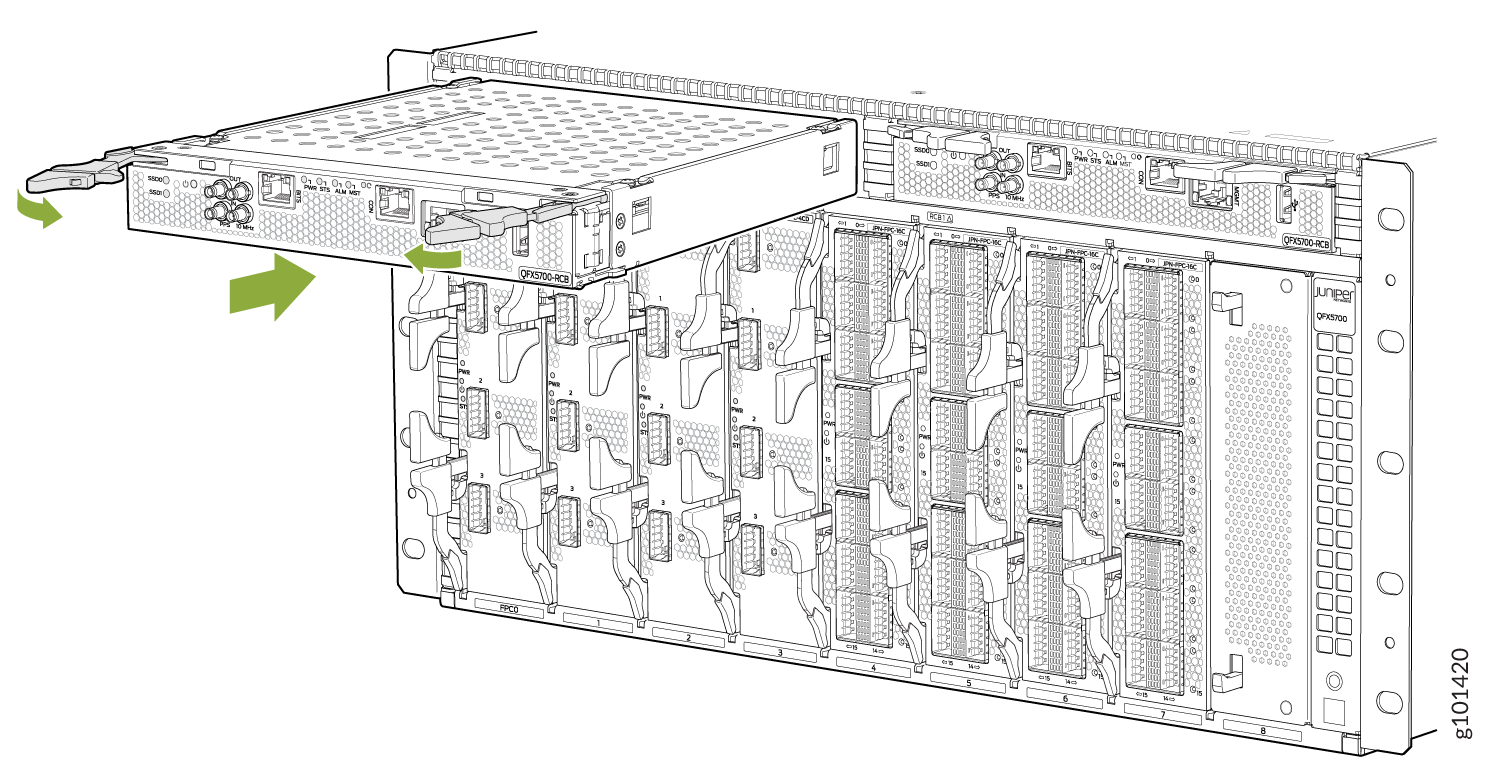
- Slide the RCB card all the way into the slot until the
handle holes align. See Figure 3.Figure 3: Insert the RCB into the Slot
You can install the optional cable management kit after the card is installed.
Remove a QFX5700 RCB
If you have the optional line-card cable management system, it’s not necessary to remove the cable management system before removing the line card.
Before you remove a line card from the switch chassis:
Ensure that you have taken the necessary precautions to prevent electrostatic discharge (ESD) damage. See Prevention of Electrostatic Discharge Damage.
If there are any optical cables (including transceivers installed in the line card), remove them before you remove the line card.
Ensure that you know how to handle and store the line card.
Ensure that you have the following parts and tools available to remove a line card from a QFX5700 chassis:
ESD grounding strap
An antistatic bag or an antistatic mat
Note:Placing a line card in an electrostatic bag might require a second person to assist with sliding the line card into the bag.
Replacement line card or a cover for the empty slot
To remove a line card from a QFX5700 switch chassis:
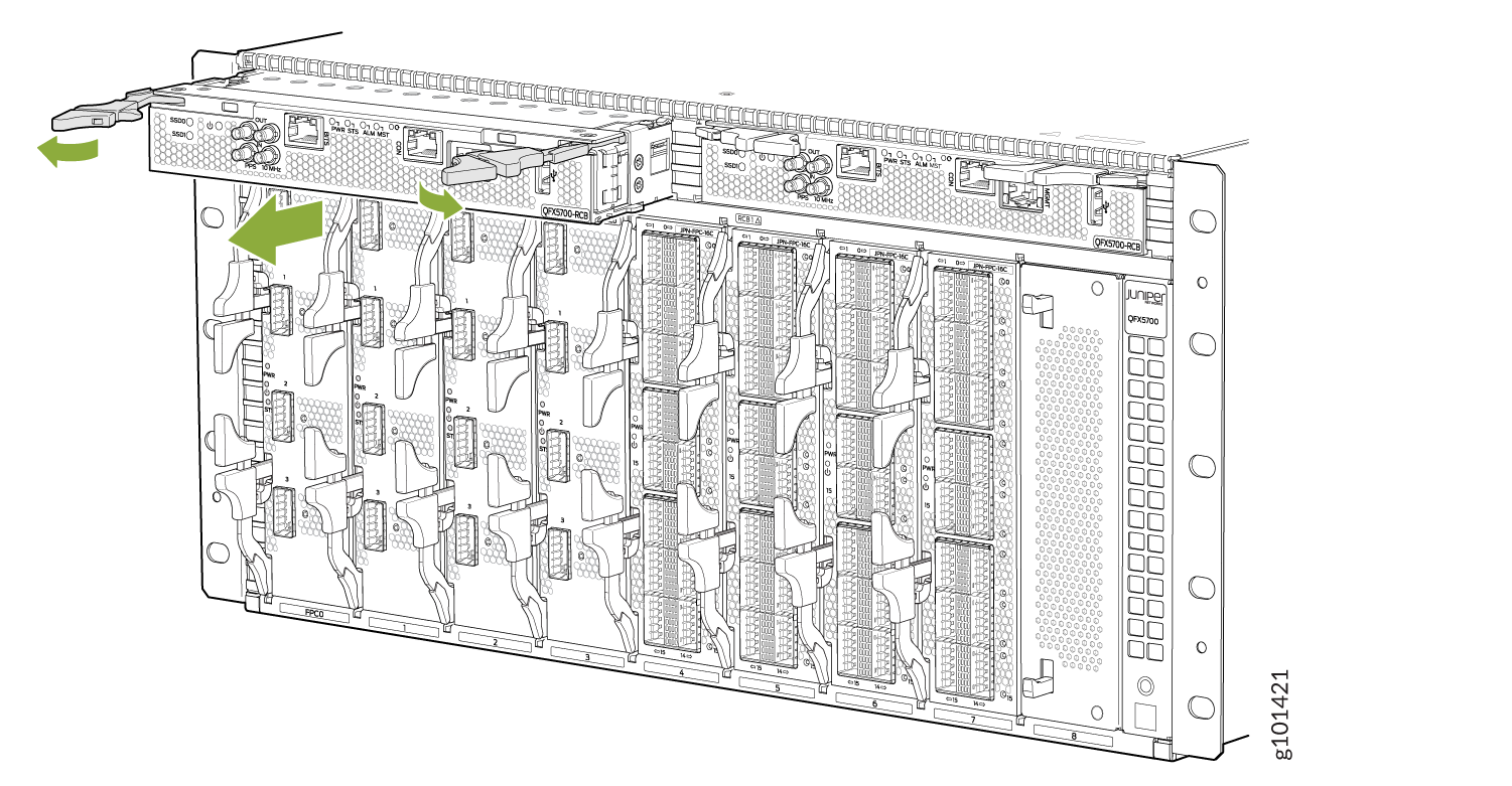
- Unscrew the line card from the chassis. See Figure 4.Figure 4: Remove a QFX5700 RCB
Install a QFX5700 FEB Board
Before installing a FEB board, you will need to remove the fan tray.
To install a FEB board in FEB1, remove Fan tray 1 and install FEB1.
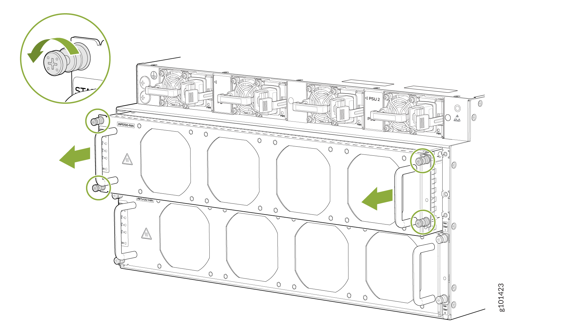
There are two FEB slots, and each FEB board is plugged in from the rear side.
The fan tray removal shown in the picture above is for representative purposes only. Remove Fan Tray 1 to install FEB1 and remove Fan Tray 0 to install FEB0.
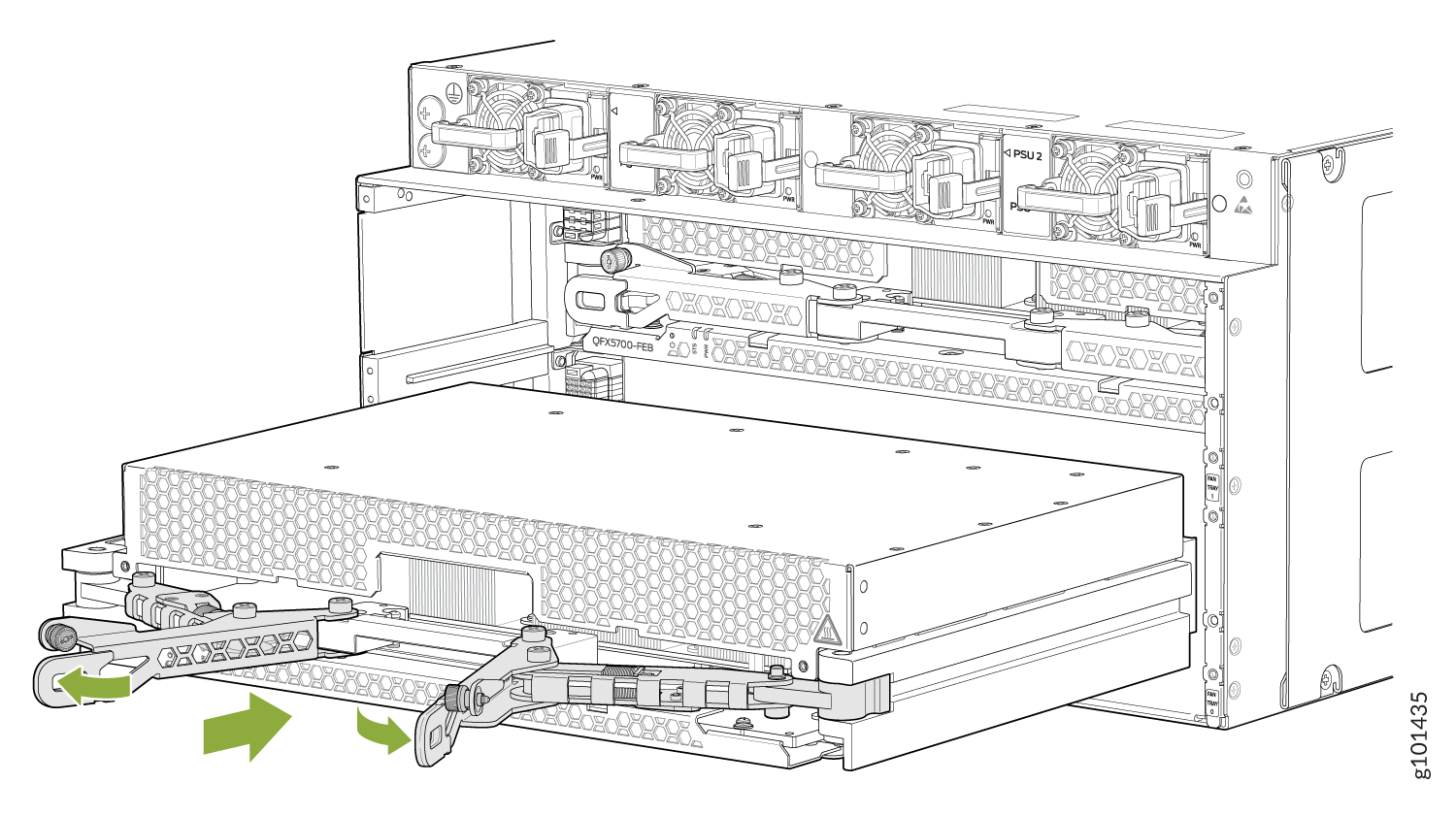
Lock the ejectors using the captive screws after you plug in the FEB board.

After you install FEB0, install Fan Tray 0 and after you install FEB1, install Fan Tray 1. Both the fan trays must be attached back to the chassis after installation to ensure uninterrupted services.
Remove a FEB Board
To remove a FEB Board, unlock the captive screws.
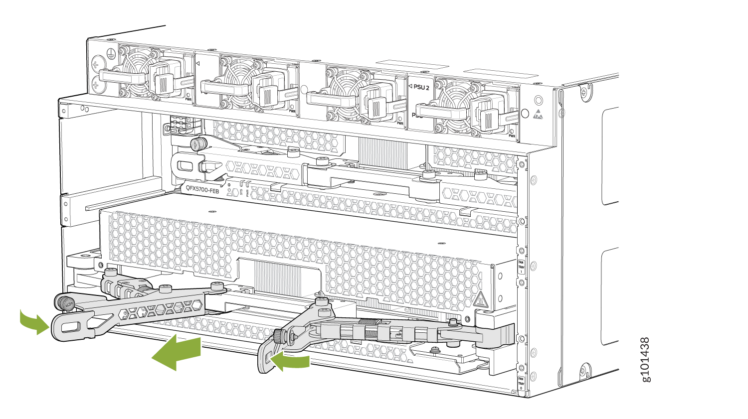
Unlatch the ejectors and plug out the FEB board.
Remove Fan tray 1 and remove FEB1.
Install an FPC Board
QFX5700 supports these FPC Boards (Inbuilt support for MACSEC, PTP Class C) – (FRS+)
16x 40GE/100GE - QSFP+/QSFP28
4x 200GE/400GE - QSFP5628-DD/QSFP56-DD
20 X 10GE/25GE/50GE - SFP/SFP+/SFP28/SFP56
QFX5700-FEB (TD4 based) supports FPC installation from slot 0 to slot 7. Ensure that you mount a blank FPC on slot 8.
To install a FPC Board:
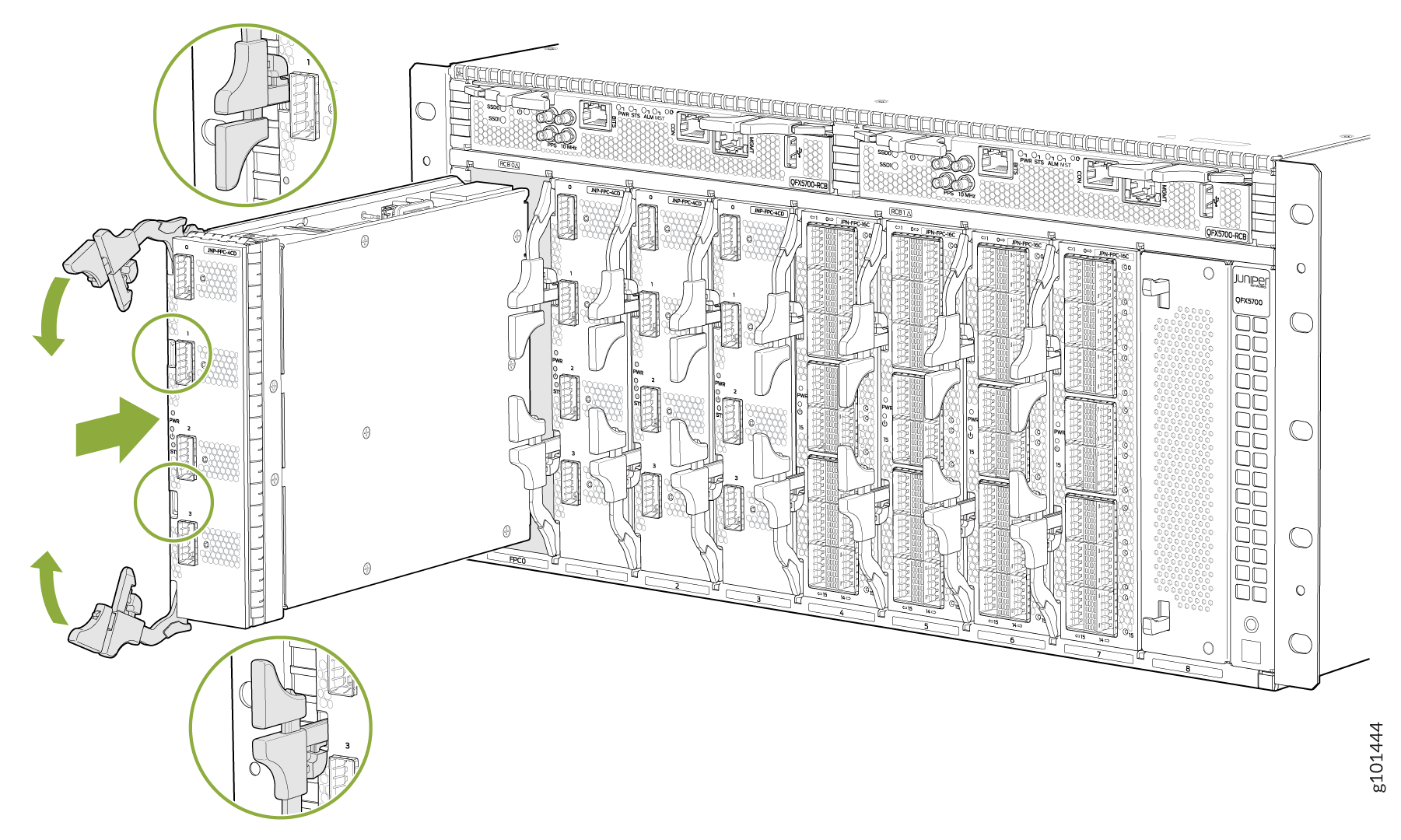
Ensure that the ejectors are firmly locked in position.

Remove an FPC Board
Unlatch the ejectors and remove the FPC board.