QFX5241-64OD and QFX5241-64QD Management Panel
QFX5241-64OD and QFX5241-64QD Management Panel
The management panel is located in the front panel of a QFX5241-64OD or QFX5241-64QD switch. You can find the management panel to the right of the port panel. Apart from the 64 network ports in the ports panel, both the QFX5241-64OD and QFX5241-64QD switches offer the following ports in the management panel:
-
Two SFP28 Ports—Supports data transmission speeds of up to 10 Gbps using SFP28 transceivers. The SFP28 ports are numbered 64 and 65.
-
One USB 3.0 port—Primarily used for storage and file transfers. For example, use this port to connect a USB drive to perform upgrades, export configuration files, or save log files.
-
One RJ-45 console (CON) port—Provides direct serial communication with the switch to support tasks such as initial configuration, troubleshooting, and recovery.
-
One RJ-45 management (MGMT) port—Supports out-of-band management of the switch. The typical use cases include secure management, remote management, monitoring, and logging.
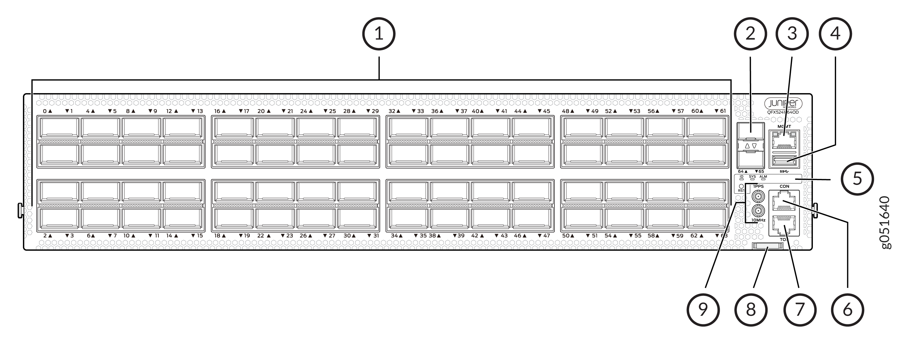
1 — Network ports panel (with 64 800GbE OSFP ports) | 6 — RJ-45 console port (CON) |
2 — SFP28 ports | 7 — Time of Delay (TOD) port |
3 — RJ-45 Management port (MGMT) | 8 — Chassis serial number pull-out |
4 — USB 3.0 port | 9 — Clock input and output connectors (10 MHz and 1 PPS) |
5 — Status LEDs (ID, SYS, ALM) and reset (RST) button |
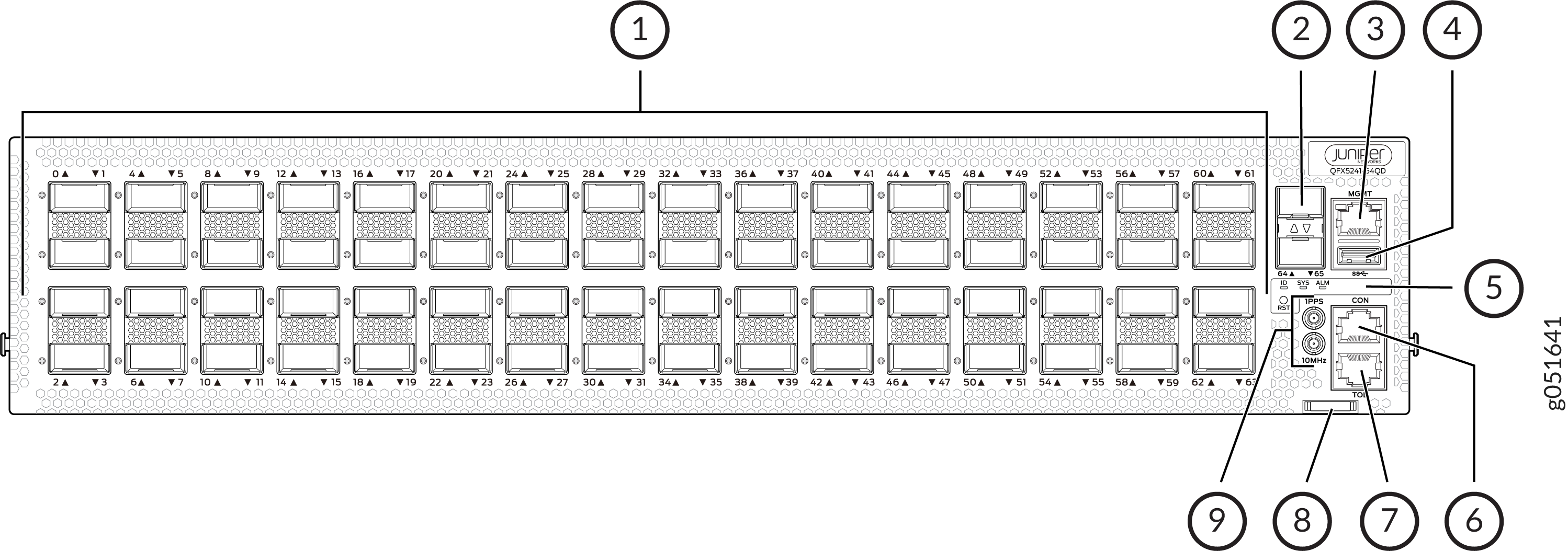
QFX5241-64OD and QFX5241-64QD Management Panel LEDs
The management panel in the QFX5241-64OD and QFX5241-64QD switches has the following LEDs:
-
Chassis Status LEDs
-
Management port LEDs
-
SFP28 port LEDs
The following sections explain how to interpret these LEDs.
QFX5241-64OD and QFX5241-64QD Chassis Status LEDs
The QFX5241-64OD and QFX5241-64QD switches have three LED types that indicate system status. You can find these LEDs to the right of the network ports (see Figure 3 and Figure 4).
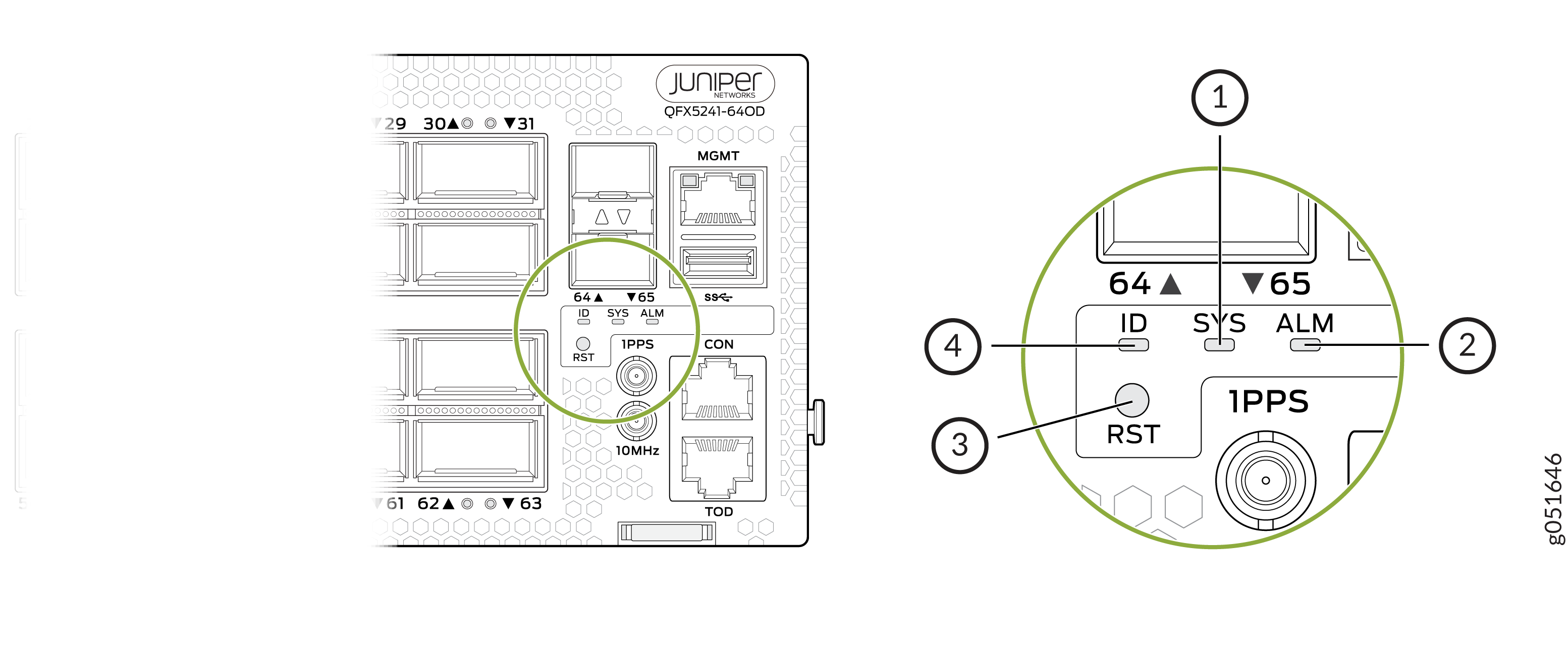
1 — SYS—System status | 3 — RST—Reset button. You can find the reset button beneath the ID LED. The reset button is not a status LED, although it is located in this panel. Note:
When you use the reset button, the device reboots. However, the existing configuration of the switch does not change. That is, the device does not return to the factory-default configuration. |
2 — ALM—Chassis alarm or fault | 4 — ID—Serves as a locator or identification indicator for the switch |
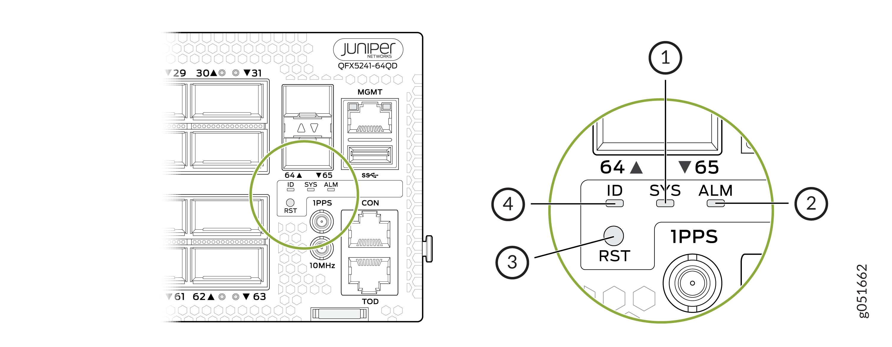
You can view the colors of the three LEDs remotely through the CLI by issuing the
operational mode command show chassis led:
user@host> show chassis led
 -----------------------------------
LEDs status:
    Alarm LED : Red
    Beacon LED: Off
    System LED: Green

Interface               STATUS LED      LINK/ACTIVITY LED
---------------------------------------------------------
et-0/0/0                N/A             Off
et-0/0/1                N/A             Off
et-0/0/2                N/A             Off
et-0/0/3                N/A             Off
et-0/0/4                N/A             Off
et-0/0/5                N/A             Off
et-0/0/6                N/A             Off
et-0/0/7                N/A             Off
et-0/0/8                N/A             Off
et-0/0/9                N/A             Off
et-0/0/10               N/A             Green
et-0/0/11               N/A             Off
et-0/0/12               N/A             Off
et-0/0/13               N/A             Off
et-0/0/14               N/A             Off
et-0/0/15               N/A             Off
et-0/0/16               N/A             Green
et-0/0/17               N/A             Off
et-0/0/18               N/A             Green
et-0/0/19               N/A             Off
et-0/0/20               N/A             Off
et-0/0/21               N/A             Off
et-0/0/22               N/A             Off
et-0/0/23               N/A             Off
et-0/0/24               N/A             Off
et-0/0/25               N/A             Off
et-0/0/26               N/A             Green
et-0/0/27               N/A             Green
et-0/0/28               N/A             Green
et-0/0/29               N/A             Off
et-0/0/30               N/A             Green
et-0/0/31               N/A             Off
et-0/0/32               N/A             Off
et-0/0/33               N/A             Off
|
Name |
Color |
State |
Description |
|---|---|---|---|
|
ALM (Alarm) |
Unlit |
Off |
The switch is halted, or there is no alarm. Note:
The ALM LED glows green during BIOS booting. |
|
Red |
On steadily |
A major hardware fault has occurred, such as a temperature alarm, power failure, or media failure. The device has halted. Use the CLI commands To troubleshoot, perform the following:
|
|
|
Yellow |
On steadily |
A minor system level alarm has occurred, such as a software error or a missing rescue configuration. Use the CLI commands To troubleshoot, perform the following:
|
|
|
SYS (System) |
Unlit |
Off |
The device is powered off or halted. Note:
The SYS LED glows green during BIOS booting. |
|
Green |
On steadily |
Junos OS Evolved is loaded on the device. |
|
|
ID (Identification) |
Unlit |
Off |
The beacon feature is not enabled on the device. Enable this
feature by using the Note:
The ID LED glows green during BIOS booting. |
|
Blue |
Blinking |
The beacon feature is enabled on the device. Disable this
feature by using the |
|
|
Tip:
To know the status of the beacon, use the user@host> show chassis beacon
OFF
|
|||
Management Port LEDs
The RJ-45 management port on the QFX5241-64OD and QFX5241-64QD switches has two LEDs that indicate link status and link activity. The management port is labeled MGMT.
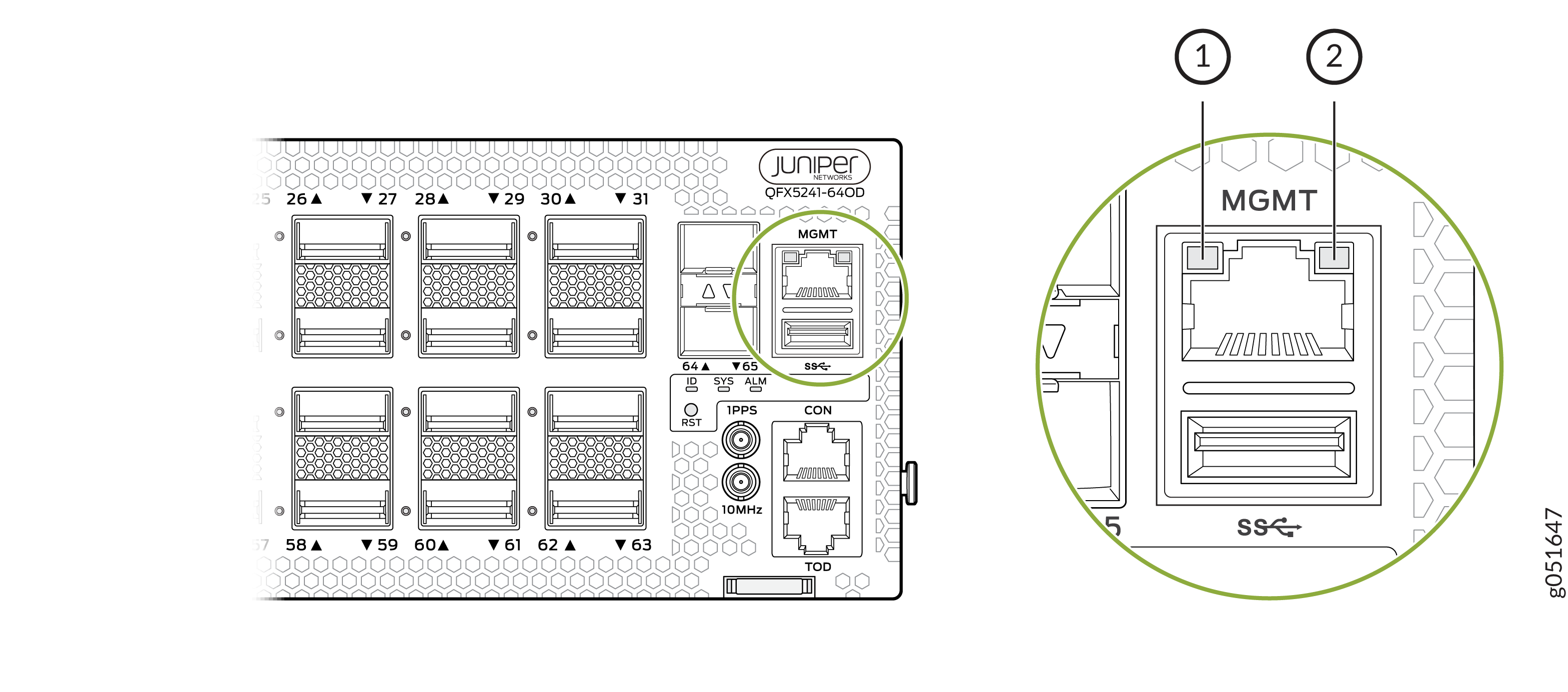
1 — Status LED | 2 — Link activity LED |
|
LED |
Color |
State |
Description |
|---|---|---|---|
|
Link activity |
Unlit |
Off |
No link is established. There is a fault, or the link is down. |
|
Green |
On steadily |
A link is established. However, there is no link activity. |
|
|
Blinking or flickering |
A link is established, and there is link activity. |
||
|
Status |
Unlit |
Off |
Either the port speed is 10 Mbps or the link is down. |
|
Green |
On steadily |
The port speed is either 1 Gbps or 100 Mbps. |
The management panel also has two SFP28 ports with one LED each.
|
LED |
Color |
State |
Description |
|---|---|---|---|
|
Link activity |
Unlit |
Off |
No link is established. There is a fault, or the link is down. |
|
Green |
On steadily |
A link is established. However, there is no link activity. |
|
|
Blinking or flickering |
A link is established, and there is link activity. |