QFX5241-64OD and QFX5241-64QD Cooling System
QFX5241-64OD and QFX5241-64QD Cooling System Description
The components of the cooling system work together to keep the switch within the acceptable temperature range. The cooling system consists of the following components:
During normal operation, the fans in the fan module operate at moderate or less than full speed. The cooling system offers N+1 redundancy for the fan module. If a fan fails or the ambient temperature rises above a threshold, the cooling system of the switch automatically adjusts the speed of the remaining fans. This speed adjustment helps to keep the temperature within the acceptable range. If the maximum temperature specification is exceeded and the system cannot be adequately cooled, the switch shuts down some or all of the hardware components.
Fan Modules
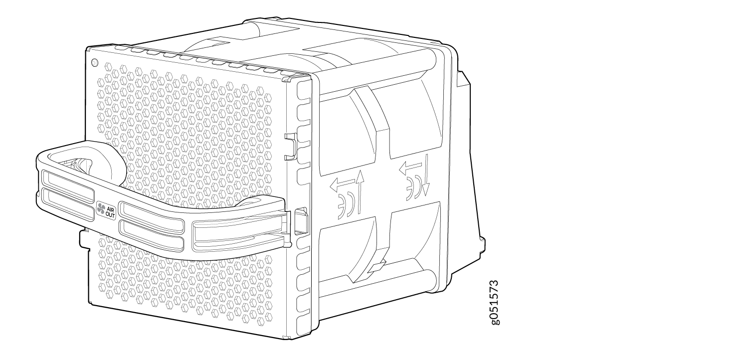
The QFX5241-64OD and QFX5241-64QD have four hot-insertable and hot-removable field-replaceable fan modules (QFX5240-2U-FANAO) installed at the rear of the switch. Each fan module houses two 80 mm x 80 mm counter-rotating rotors.
The fan modules in the QFX5241-64OD and QFX5241-64QD are FRUs designed for port-to-FRU airflow, which is also known as airflow out (AFO) or front-to-back airflow. The fan modules are numbered from 0 through 3. Each fan module is 2-U high and has an associated LED to indicate its status.
The fan speed varies based on the temperature of internal components, optics modules, and the ambient temperature. The maximum speed at which fans operate depends on the ambient temperature that you have set. As the fan speed increases, the power consumed by the fans increases. As a result, the device consumes more power when the temperature is high because the fans run faster to maintain the operating temperature of the chassis within the configured limits.
The QFX5241-64OD and QFX5241-64QD switches must operate with all the four fan modules installed. If you need to replace a faulty fan module, see QFX5241-64OD and QFX5241-64QD Fan Module Status LED.
QFX5241-64OD and QFX5241-64QD Fan Module Status LED
Each fan module has one bicolor status LED.
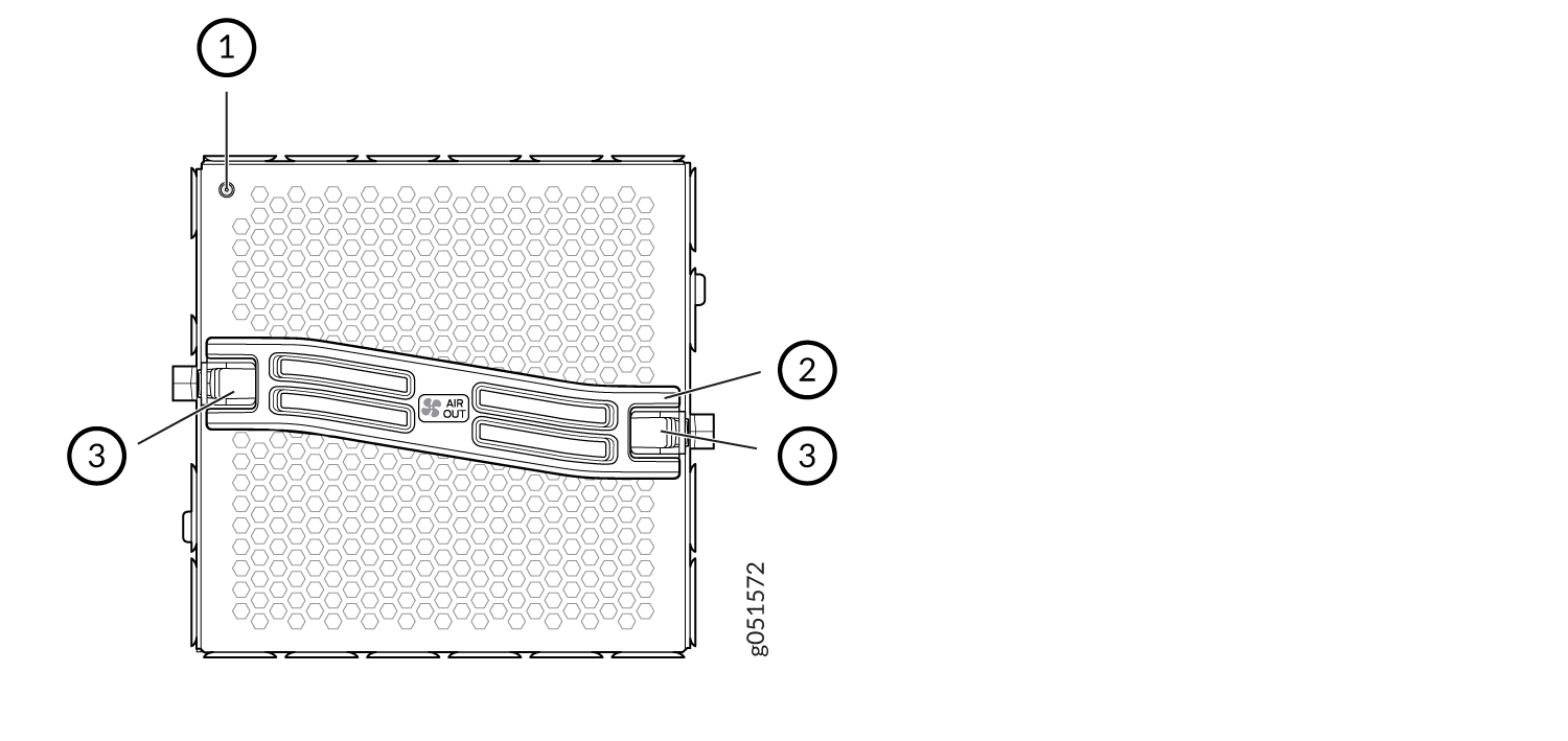
1 — Fan module LED | 3 — Lock release handle |
2 — Handle |
Table 1 describes the behavior of the fan module status LED.
|
Color |
State |
Description |
|---|---|---|
|
Green |
On steadily |
Fan module is functioning normally. |
|
Red |
On steadily |
Fan module is faulty and malfunctioning. |
|
Unlit |
Off |
Fan module experiences input power failure. |
Under normal operating conditions, the fan modules operate at a moderate speed. Temperature sensors in the chassis monitor the temperature within the chassis.
The system raises an alarm if a fan module fails or if the ambient temperature inside the chassis rises above the acceptable range. If the temperature inside the chassis rises above the threshold temperature, the system shuts down automatically.
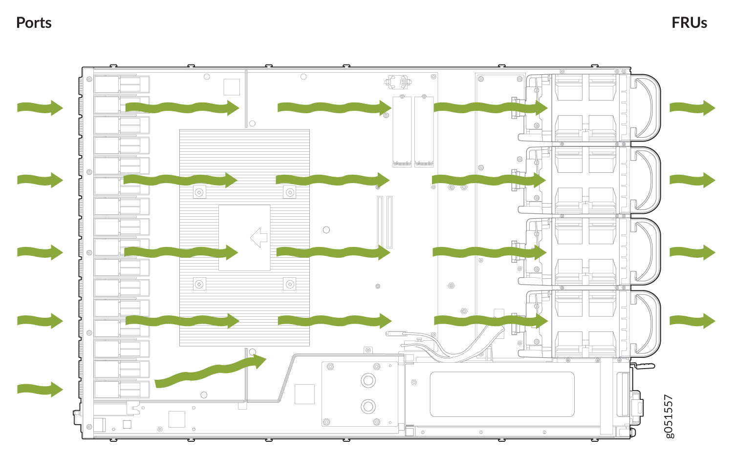
Airflow
The switch has a front-to-back (airflow out or AFO) airflow design cooling system. The switch pulls air through the front of the chassis toward the fan modules, and exhausts the air from the rear of the switch.
Power Supply Cooling System
The QFX5241-64OD and QFX5241-64QD PSUs are installed at the rear of the chassis. The PSUs are self-cooling. Each PSU has its own fan and is cooled by its own internal cooling system. The PSUs in QFX5241-64OD and QFX5241-64QD switches support front-to-back airflow (airflow out or AFO).
In the QFX5241-64OD and QFX5241-64QD switches, the AC PSU fan speed is controlled by the internal microcontroller firmware and adjusts dynamically based on load conditions and temperature. The operational range is 4,000 RPM to 28,000 RPM.
-
Under normal operating conditions, fan speeds vary within this full range.
-
During high-temperature conditions, fan speeds typically operate between 18,000 RPM and 28,000 RPM to ensure optimal thermal management.
These speed variations are expected behavior and do not impact system functionality or AC PSU fan longevity.