Unpack and Mount the QFX5240 Switch
Unpack a QFX5240 Switch
The QFX5240 chassis is a rigid sheet-metal structure that houses the hardware components. A QFX5240 switch is shipped in a cardboard carton, secured with foam packing material.
The QFX5240 switch is maximally protected inside the shipping carton. Do not unpack the switch until you are ready to begin installation.
To unpack a QFX5240 switch:
- Move the shipping carton to a staging area as close to the installation site as possible, but where you have enough room to remove the system components.
- Position the carton so that the arrows are pointing up.
- Open the top flaps on the shipping carton.
- Remove the switch out of the packing material from the pellet
- Verify the contents of the carton against the inventory included in the carton. Table 1 lists the inventory of components supplied with a QFX5240.
- Save the shipping carton and packing materials in case you need to move or ship the switch later.
|
Component |
Quantity |
|---|---|
|
Chassis |
1 |
|
Fan modules |
4, factory installed |
|
Power supplies
|
2, factory installed |
|
Rack mount kit for QFX5240-2U-4PRMK
The order number for a spare rack mount kit is QFX5240-2U-4PRMK. |
1 1 1 3 |
|
Rack mount assembly drawing, which is part of the RMK |
1 |
|
Power cords with plugs appropriate to your geographical location |
2 |
|
Documentation roadmap card |
1 |
|
Warranty |
1 |
- RJ-45 to DB-9 adapter (JNP-CBL-RJ45-DB9)
- RJ-45 to USB-A adapter (JNP-CBL-RJ45-USBA)
- RJ-45 to USB-C adapter (JNP-CBL-RJ45-USBC)
If you want to use RJ-45 to USB-A or RJ-45 to USB-C adapter you must have X64 (64-Bit) Virtual COM port (VCP) driver installed on your PC. See, https://ftdichip.com/drivers/vcp-drivers/ to download the driver.
Update Base Installation Data
Update the installation base data if any addition or change to the installation base occurs or if the installation base is moved. Juniper Networks is not responsible for not meeting the hardware replacement SLA for products that do not have accurate installation base data.
Update your installation base at https://supportportal.juniper.net/s/CreateCase .
Mount the QFX5240 Switch in a Four-Post Rack
You can mount QFX5240 switches only on a four-post 19-in. rack using the QFX5240-2U-4PRMK rack mount kit provided with the switch. The rack mount kit can be adapted for a four-post rack-only installation. A four-post installation evenly supports the chassis by all four corners.
The rack mount kit contains two front-mounting rail assemblies and two rear-mounting blades that match the front-mounting rails. This configuration allows either end of the switch chassis to be mounted flush with the rack and still be adjustable for racks with different depths.
The front and rear rack rails must be spaced between 28 in. (71.1 cm) and 32 in. (81.2 cm) front to back.
Before You Begin Rack Mounting
Before you begin mounting a QFX5240 switch in the rack:
A QFX5240 requires two people for installation, one person to lift the device into place and another person to attach the device to the rack. If you are installing the QFX5240 above 60 in. (152.4 cm) from the floor, we recommend that you remove the power supplies and fan modules to minimize the weight before attempting to install the device.
If you are mounting multiple devices on a rack, mount the heaviest device in the lowest position of the rack first. Proceed to mount the rest of the devices from the bottom to the top of the rack to minimize the risk of the rack toppling.
Mount the QFX5240 in a Four-Post Rack
Unpack the switch and place it on a flat stable surface.
Verify the parts received.
Ensure that you have the following tools and parts available:
An ESD grounding strap—not provided
QFX5240-2U-4PRMK rack mount kit (RMK)—provided
Two slide rail assemblies
One packet of screws
- Prepare the Slide Rail Assembly to Install in the Rack
- Install the Slide Rail Assembly in the Rack
- Mount the Switch in the Rack
Prepare the Slide Rail Assembly to Install in the Rack
The slide rail assembly consists of three parts:
Outer rail
Slider rail
Inner rail bracket
Remove the Inner Rail Bracket from the Slide Rail Assembly
Wrap and fasten one end of the ESD grounding strap around your bare wrist, and connect the other end to a site ESD point.
Hold the slide rail assembly and pull the inner rail bracket and the slider rail out to their full extended position until you hear a click sound.
Push the white tab on the inner rail bracket forward and pull the bracket out of the slide rail assembly and place it aside.
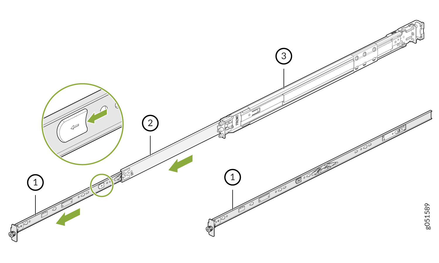
Inner rail bracket
Slider rail
Outer rail
Press the latch on the slider rail down and retract the slider rail into the slide rail assembly.
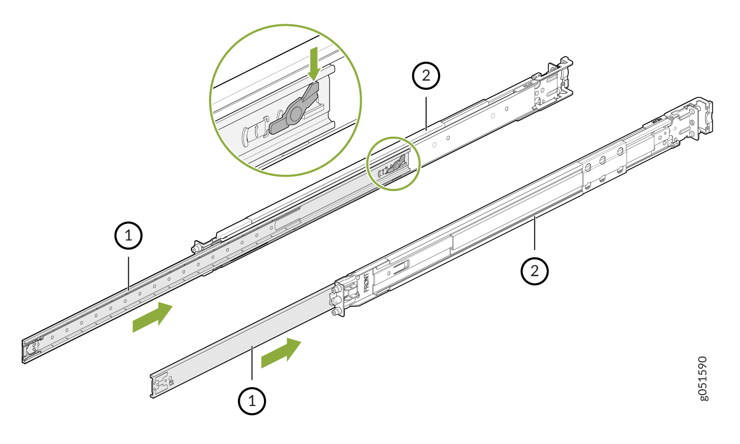
Slider rail
Outer rail
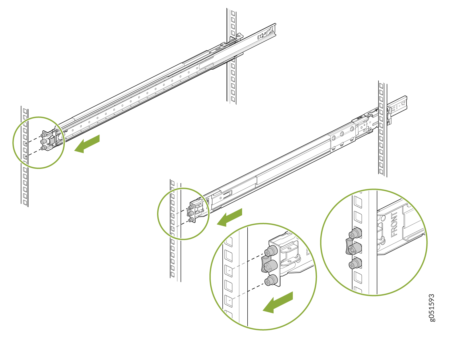
Install the Slide Rail Assembly in the Rack
Move the latch on the rear end of the slide rail assembly to the open position.
Align the rear end of slide rail assembly with the rear rack-post holes that you want to use.
The mounting pegs on the outer rail enter the rear rack-post holes from the inside of the rack post.
Push the outer rail rear mounting pegs into the rear rack-post holes. You will hear a click sound.
Move the latch to the close position.
The rear end of the outer rail wraps around the outside of the rear rack post.
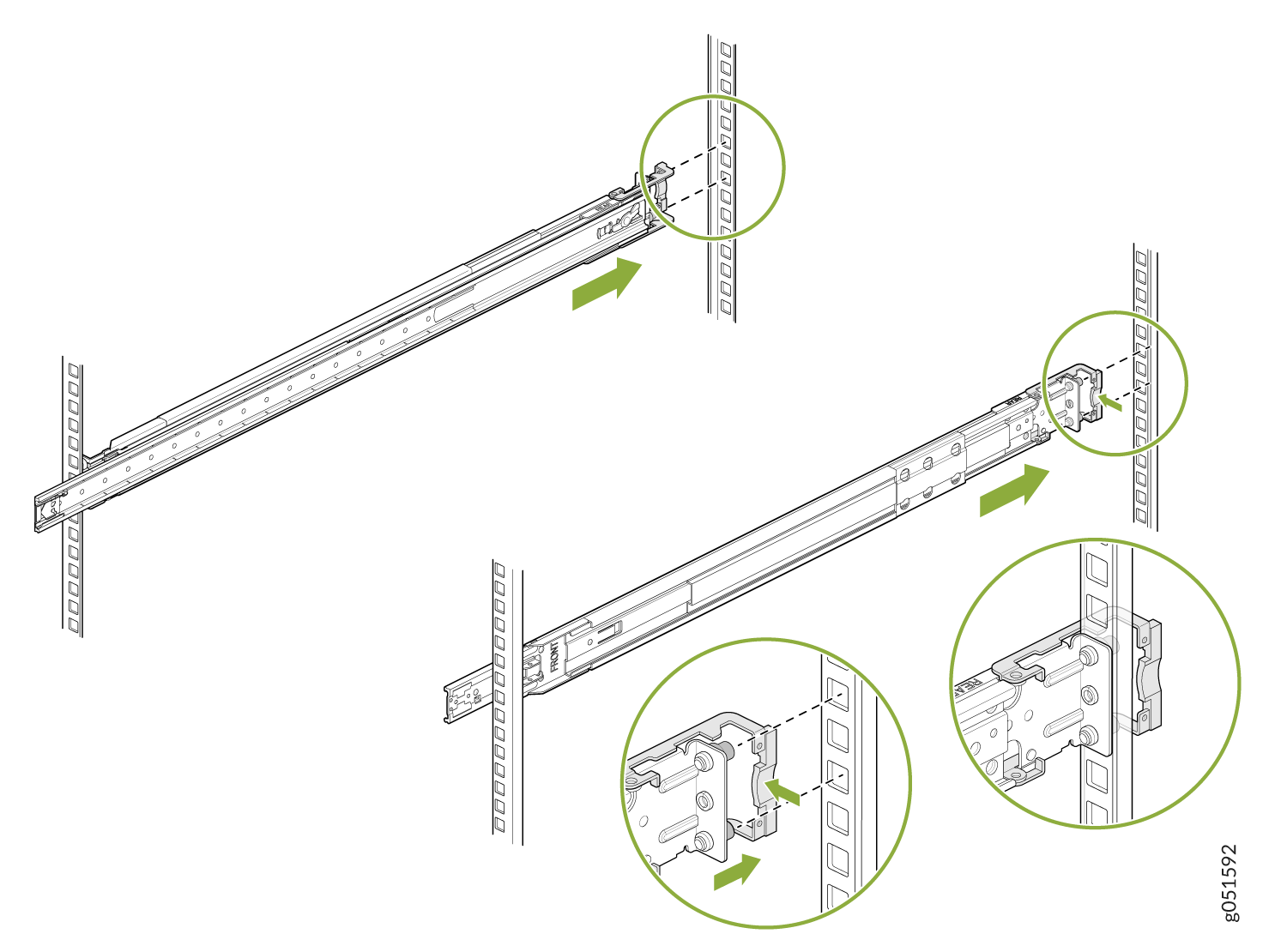
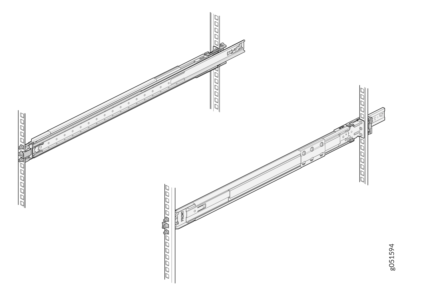
Adjust the slider rail length and push the front-mounting pegs on it into the front rack-post holes. You will hear a click sound.
- The slide rail assembly is fully installed. Verify that both the slide rail assemblies are
at the same height each other and are level front-to-back.
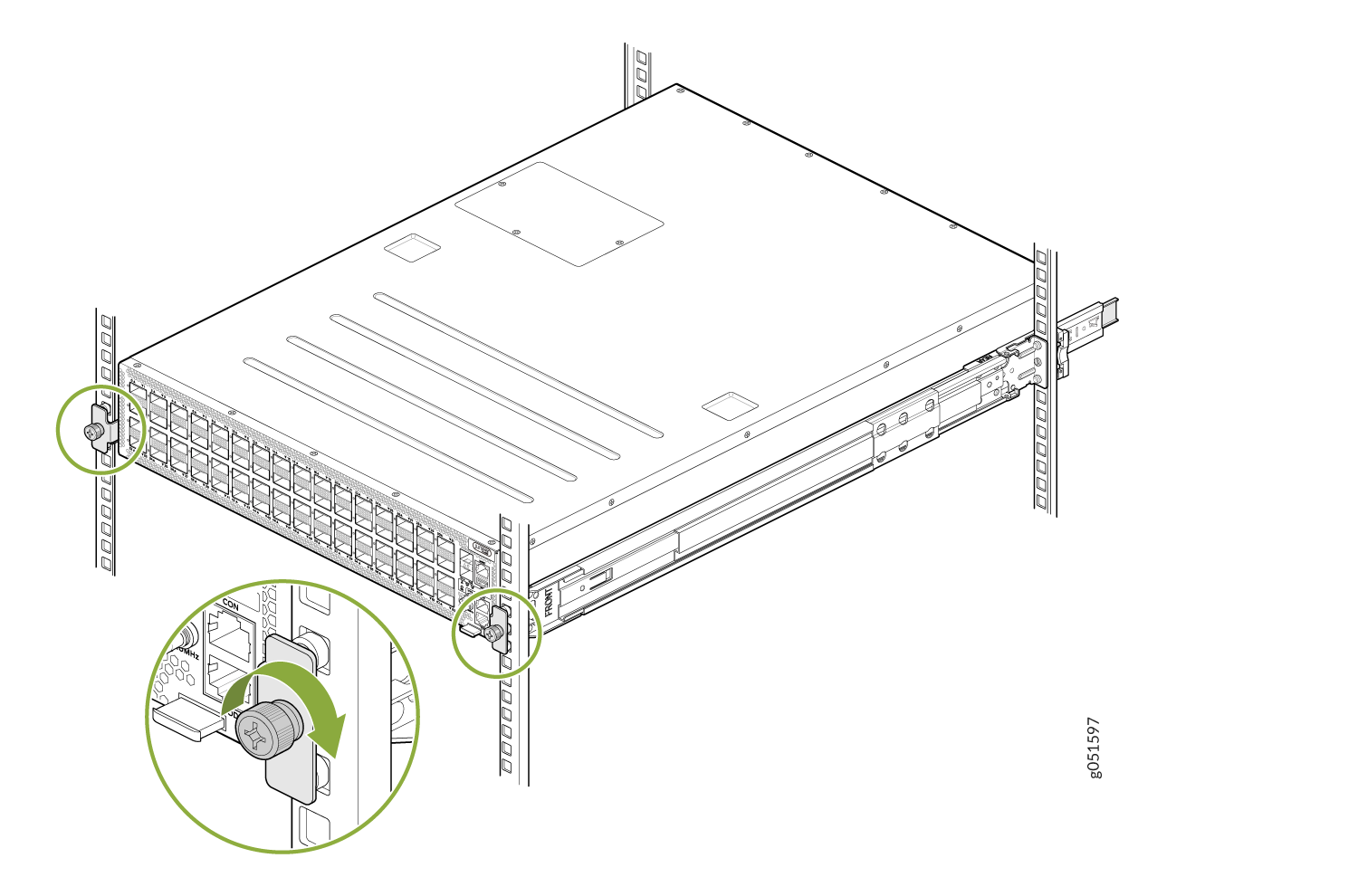
Mount the Switch in the Rack
Pull the slider rails out to their full extended lock position, and ensure that the ball bearing retainer is located at the front of the slider rail.
Lift the switch and align the rear of the inner rail brackets with the front ends of the slider rails on the rack.
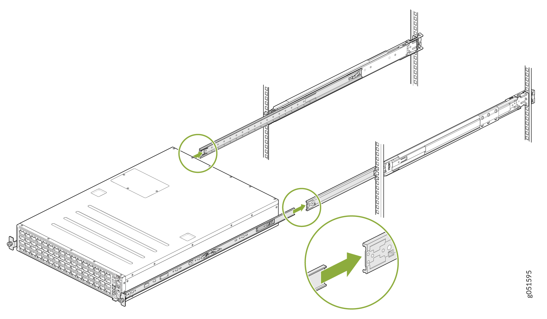
Push the inner rail brackets into the slider rails until you can no longer proceed.
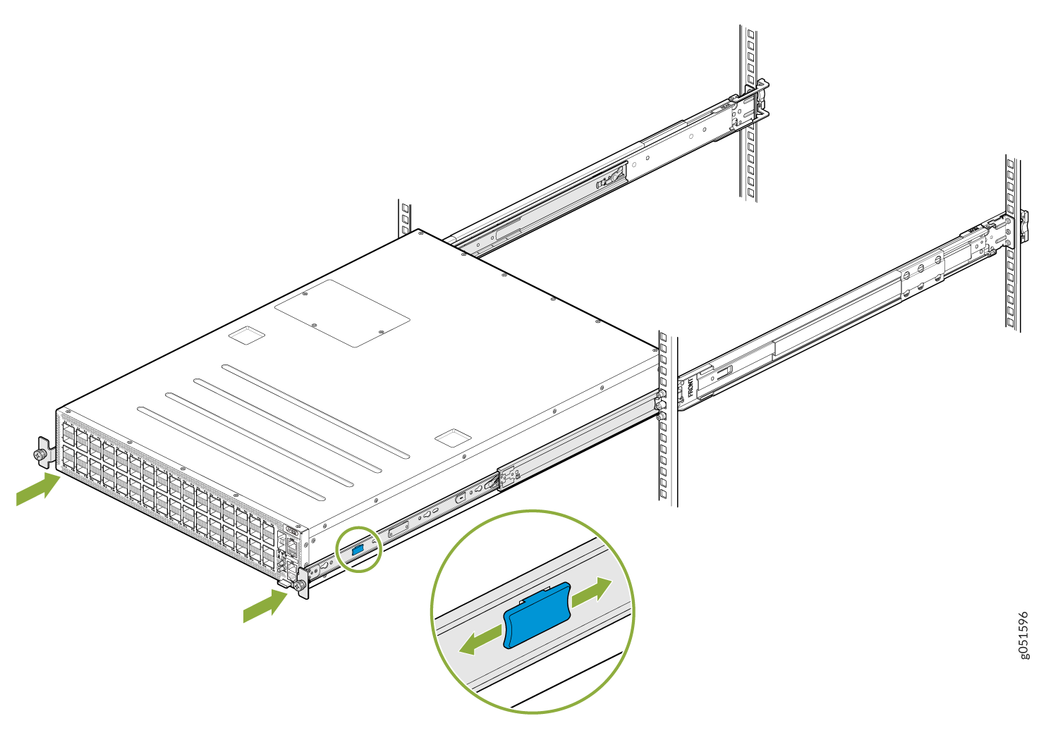
Tighten the two thumbscrews to secure the switch.