Return a QFX5240 Chassis or Components
Locate the Serial Number on a QFX5240 Device or Component
If you are need to return a switch or component to Juniper Networks for repair or replacement, you must locate the serial number of the switch or component. You must provide this serial number to the Juniper Networks Technical Assistance Center (JTAC) when you contact them to obtain a Return Materials Authorization (RMA).
If the switch is operational and you can access the CLI, you can list serial numbers for the switch and for some components with a CLI command. If you do not have access to the CLI or if the serial number for the component does not appear in the command output, you can locate the serial number ID label on the switch or component.
If you want to find the serial number ID label on a component, you need to remove the component from the switch chassis, for which you must have the required parts and tools available.
- List the Chassis and Component Details Using the CLI
- Locate the Chassis Serial Number ID Label on a QFX5240 Switch
- Locate the Serial Number ID Labels on FRUs in a QFX5240 Switch
List the Chassis and Component Details Using the CLI
To list the switch and components and their serial numbers, use the
show chassis hardware CLI operational mode command. The
following output lists the switch components and serial numbers for a
QFX5240 switch. The output is similar for other QFX5240 switches:
user@device> show chassis hardware
Hardware inventory:
Item             Version  Part number  Serial number     Description
Chassis                                JN0000000         QFX5240-64OD
PSM 0                                  6U6LX010234424H   AC AFO 3000W PSU
PSM 1                                  6U6LX01023442EZ   AC AFO 3000W PSU
Routing Engine 0 REV 01   611-176059   AN45037787        RE-QFX5240
CB 0             REV 01   650-175147   AN45056963        QFX5240-64OD
FPC 0                     BUILTIN      BUILTIN           QFX5240-64OD
  PIC 0                   BUILTIN      BUILTIN           64X800G-OSFP
    Xcvr 1       REV 01   740-174935   1G1CVXA84800C     OSFP-2x400G-FR4
    Xcvr 3       REV 01   740-174935   1G1CVXA84800P     OSFP-2x400G-FR4
    Xcvr 4       REV 01   740-174935   1W1CVXA84600E     OSFP-2x400G-FR4
    Xcvr 6       XXXX     NON-JNPR     UP6T020006        OSFP-2x400G-FR4
    Xcvr 10      REV 01   740-174933   X9RB9W8           OSFP-800G-DR8
    Xcvr 12      XXXX     NON-JNPR     INNBD6580004      UNKNOWN
    Xcvr 13      REV 01   740-174935   1W1CVXA84600B     OSFP-2x400G-FR4
    Xcvr 15      REV 01   740-174935   1G1CVXA849008     OSFP-2x400G-FR4
    Xcvr 16      REV 01   740-174935   1W1CVXA84600C     OSFP-2x400G-FR4
    Xcvr 17      XXXX     NON-JNPR     UP6T020008        OSFP-2x400G-FR4
    Xcvr 18      REV 01   740-174935   1W1CVXA84600D     OSFP-2x400G-FR4
    Xcvr 19      REV 01   740-174935   1G1CVXA84800Y     OSFP-2x400G-FR4
    Xcvr 20      XXXX     NON-JNPR     UP6T020015        OSFP-2x400G-FR4
    Xcvr 21      REV 01   740-174933   X9SBK7B           OSFP-800G-DR8
    Xcvr 22      XXXX     NON-JNPR     UP5Q150001        OSFP-2x400G-FR4
    Xcvr 26      XXXX     NON-JNPR     INNBD6580007      UNKNOWN
    Xcvr 27      XXXX     NON-JNPR     INNBD6580021      UNKNOWN
    Xcvr 28      XXXX     NON-JNPR     INNBD6580025      UNKNOWN
    Xcvr 30      XXXX     NON-JNPR     N6WT000083        UNKNOWN
    Xcvr 42      XXXX     NON-JNPR     N6WT000067        UNKNOWN
    Xcvr 53      XXXX     NON-JNPR     INNBD6580026      UNKNOWN
    Xcvr 56      XXXX     NON-JNPR     N6WT000065        UNKNOWN
    Xcvr 58      XXXX     NON-JNPR     N6WT000068        UNKNOWN
    Xcvr 60      REV 01   740-174933   XA1CRMD           OSFP-800G-DR8
Fan Tray 0                                               QFX5240-64OD/QFX5240-64QD Fan Tray, Front to Back Airflow - AFO
Fan Tray 1                                               QFX5240-64OD/QFX5240-64QD Fan Tray, Front to Back Airflow - AFO
Fan Tray 2                                               QFX5240-64OD/QFX5240-64QD Fan Tray, Front to Back Airflow - AFO
Fan Tray 3 QFX5240-64OD/QFX5240-64QD Fan Tray, Front to Back Airflow - AFOYou must remove the fan module to read the fan serial number from the serial number ID label. The fan module serial number cannot be viewed through the CLI. Fan Tray 2 refers to the third module from the left, counting from 0.
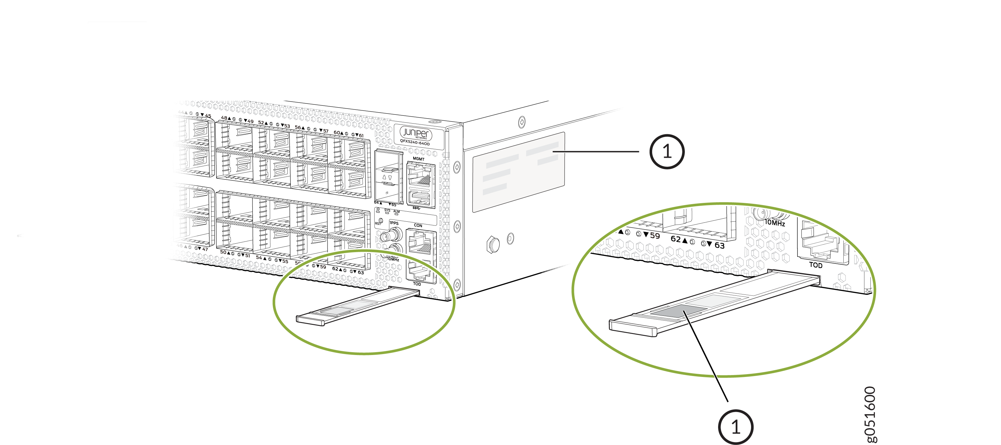
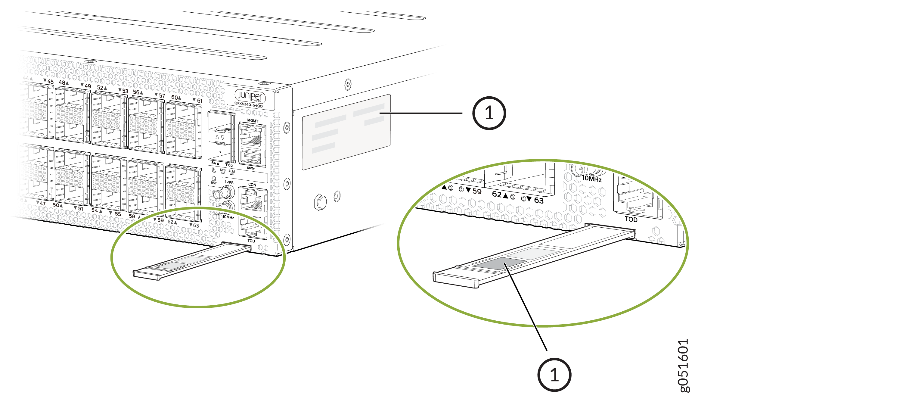
Locate the Chassis Serial Number ID Label on a QFX5240 Switch
You can find the chassis serial number in either the show chassis
hardware command output or physically on a pull-out tab located
on the right side of the QFX5240 port
panel.
See Figure 1 for the QFX5240-64OD Switch and Figure 2.
Locate the Serial Number ID Labels on FRUs in a QFX5240 Switch
The power supplies and fan modules installed in a QFX5240 switch are field-replaceable units (FRUs). For each FRU, you must remove the FRU from the switch chassis to see the FRU serial number ID label.
-
AC power supply—The serial number ID label is on the top of the AC power supply. Figure 3 shows the location of the serial number ID label on the AC power supply for QFX5240 switches.
Figure 3: Serial Number ID Label on a QFX5240 AC Power Supply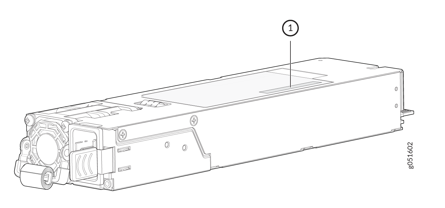 1—
1—Serial number ID label
-
Fan module—The serial number ID label is on the bottom of the fan module for QFX5240 switches. Figure 4 shows the location of serial number on QFX5240 switches. The serial number ID label is on the side of the fan module for QFX5240-48C switches.
Figure 4: Serial Number ID Label on a QFX5240 Fan Module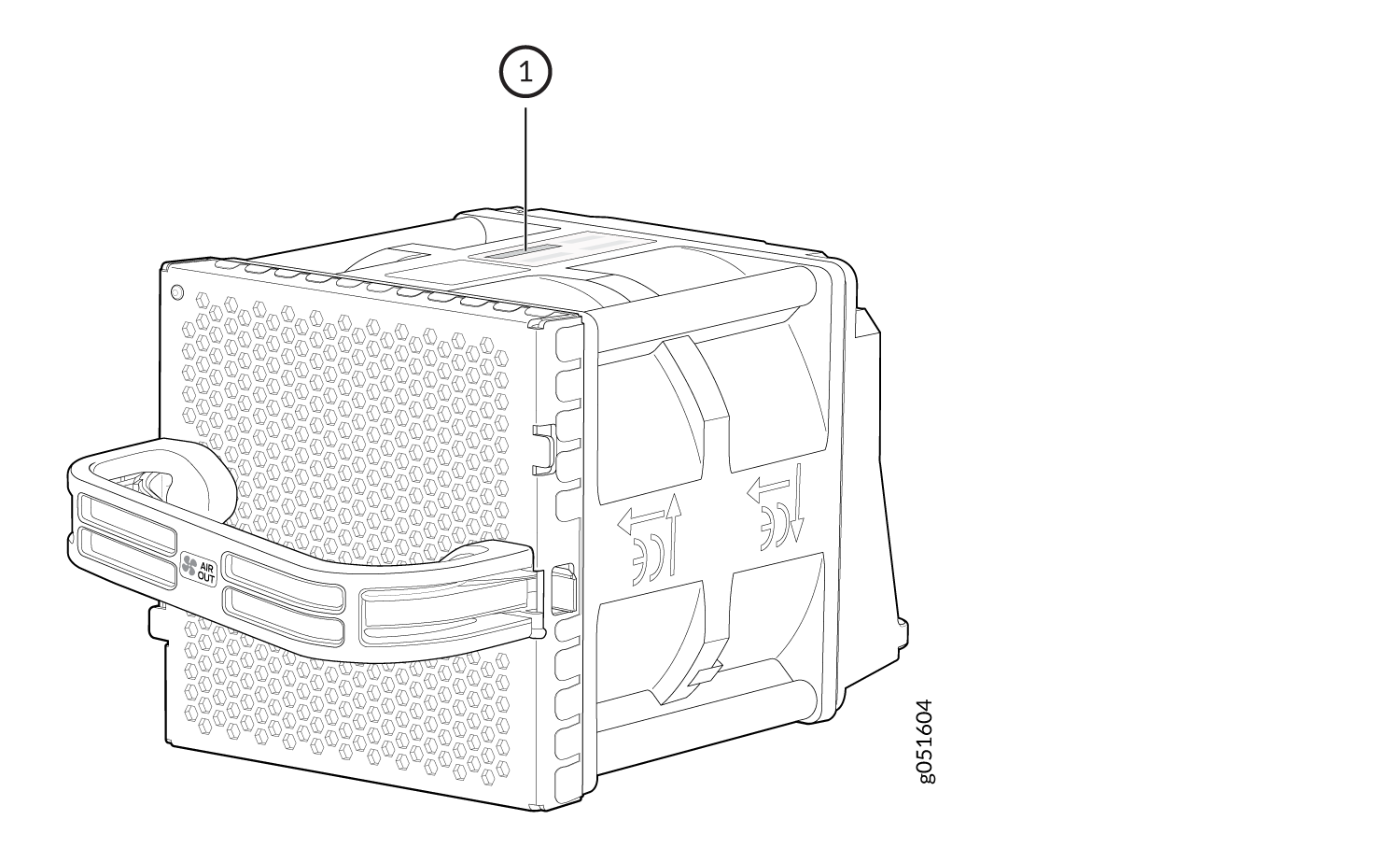 1—
1—Serial number ID label
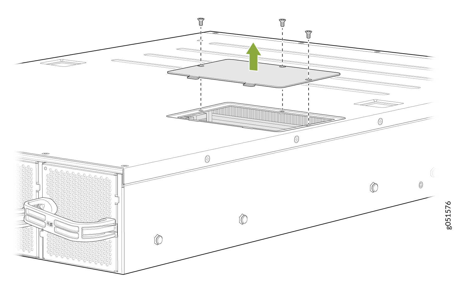
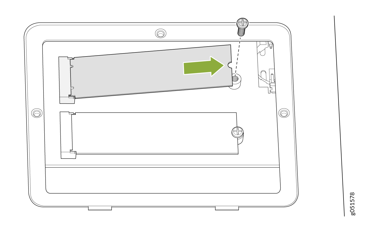
Remove the Solid-State Drives for RMA on QFX5240 Switches
The QFX5240 switches have two solid-state drives (SSDs) that store the software images, system logs, and the configuration files. Before returning a chassis to Juniper Networks as part of a Return Material Authorization (RMA), you have the option of removing the SSDs and disposing them according to your own company’s security procedures. Before you begin this procedure, ensure you have the following tools:
-
ESD grounding strip (not provided)
-
Phillips screwdriver, number 2
Use this optional procedure to remove the drives from the QFX5240 switches after the device has shut down and you’ve removed it from the rack or cabinet. The SSD doors are located on the top of the QFX5240 switch.
How to Return a Hardware Component to Juniper Networks, Inc.
If a hardware component fails, you need to contact Juniper Networks, Inc. to obtain a Return Material Authorization (RMA) number. This number is used to track the returned material at the factory and to return repaired or new components to the customer as needed.
Do not return any component to Juniper Networks, Inc. unless you have first obtained an RMA number. Juniper Networks, Inc. reserves the right to refuse shipments that do not have an RMA. Refused shipments are returned to the customer by collect freight.
For more information about return and repair policies, see the customer support webpage at https://support.juniper.net/support/.
For product problems or technical support issues, contact the Juniper Networks Technical Assistance Center (JTAC) by using the Service Request Manager link at https://support.juniper.net/support/ or at 1-888-314-JTAC (within the United States) or 1-408-745-9500 (from outside the United States).
To return a defective hardware component:
Guidelines for Packing Hardware Components for Shipment
To pack and ship individual components:
When you return components, make sure that they are adequately protected with packing materials and packed so that the pieces are prevented from moving around inside the carton.
Use the original shipping materials if they are available.
Place individual components in antistatic bags.
Write the RMA number on the exterior of the box to ensure proper tracking.
Do not stack any of the hardware components.
Pack a QFX5240 Switch or Component for Shipping
If you are returning a QFX5240 or one of its components to Juniper Networks for repair or replacement, pack the item as described in this topic.
Before you pack a QFX5240 switch or component:
-
Ensure that you have taken the necessary precautions to prevent electrostatic discharge (ESD) damage.
-
Retrieve the original shipping carton and packing materials. Contact your JTAC representative if you do not have these materials, to learn about approved packing materials. See Contact Customer Support to Obtain Return Material Authorization.
Ensure that you have the following parts and tools available:
-
ESD grounding strap.
-
Antistatic bag, one for each component.
-
If you are returning the chassis, an appropriate screwdriver for the mounting screws used on your rack or cabinet.
Pack a QFX5240 Switch for Shipping
To pack a QFX5240 switch for shipping:
- Power off the switch and remove the power cables. See Power Off a QFX5240 Switch.
- Remove the cables that connect the QFX5240 switch to all external devices.
- Remove all field-replaceable units (FRUs) from the switch.
- Have one person support the weight of the switch while another person unscrews and removes the mounting screws.
- Remove the switch from the rack or cabinet and place the switch in a large antistatic bag.
- Place the switch in the shipping carton.
- Place the packing foam on top of and around the switch.
- If you are returning accessories or FRUs with the switch, pack them as instructed in Pack QFX5240 Components for Shipping.
- Replace the accessory box on top of the packing foam.
- Close the top of the cardboard shipping box and seal it with packing tape.
- Write the RMA number on the exterior of the box to ensure proper tracking.
Pack QFX5240 Components for Shipping
Do not stack switch components. Return individual components in separate boxes if they do not fit together on one level in the shipping box.
To pack and ship QFX5240 components:
-
Place individual FRUs in antistatic bags.
-
Ensure that the components are adequately protected with packing materials and packed so that the pieces are prevented from moving around inside the carton.
-
Close the top of the cardboard shipping box and seal it with packing tape.
-
Write the RMA number on the exterior of the box to ensure proper tracking.

