Fast Track to Rack Installation and Power
This procedure walks you through the most basic steps for installing your QFX5230-64CD switch in a rack and connecting it to power.
You can install the QFX5230-64CD switch on a four-post rack by using the QFX5230-2RU-4PRMK rack mount kit (RMK). We’ll walk you through the steps to install the QFX5230 switch using the QFX5230-2RU-4PRMK RMK.
Before you install the switch, review:
Install the QFX5230-64CD Switch in a Rack
Ensure that you have the following tools and parts available:
-
An ESD grounding strap—not provided.
-
A pair of side mounting brackets that attach to the chassis—provided with the RMK.
-
A pair of front and rear mounting rails that attach to the rack posts—provided with the RMK.
To mount the device on a four-post rack:
- Place the switch on a flat, stable surface.
- Wrap and fasten one end of the ESD grounding strap around your bare wrist, and connect the other end to a site ESD point.
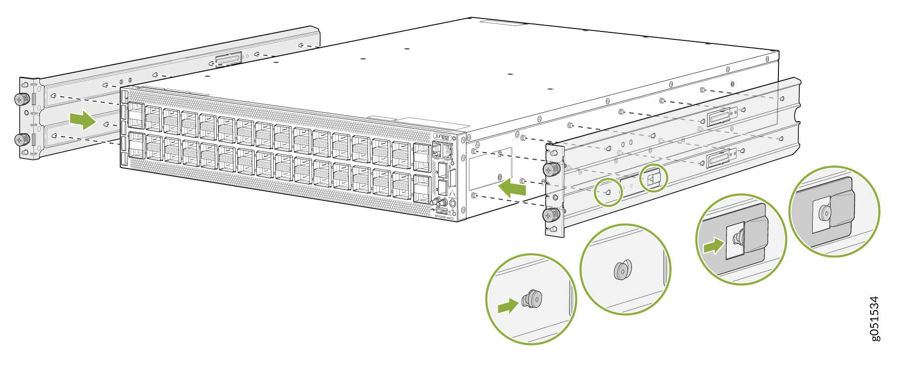
- To attach the side mounting brackets to the chassis, align the
keyholes on the mounting brackets over the shoulder screws on the chassis.
Slide the mounting brackets toward the rear of the chassis.Figure 1: Attach the Side Mounting Brackets
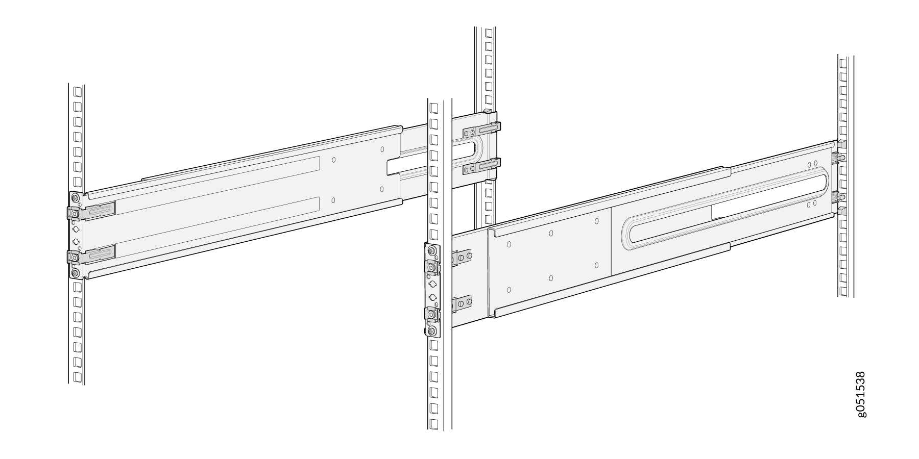
-
Assemble the mounting rails by sliding the rear floating rails into the front rails.
Figure 2: Assemble the Mounting Rails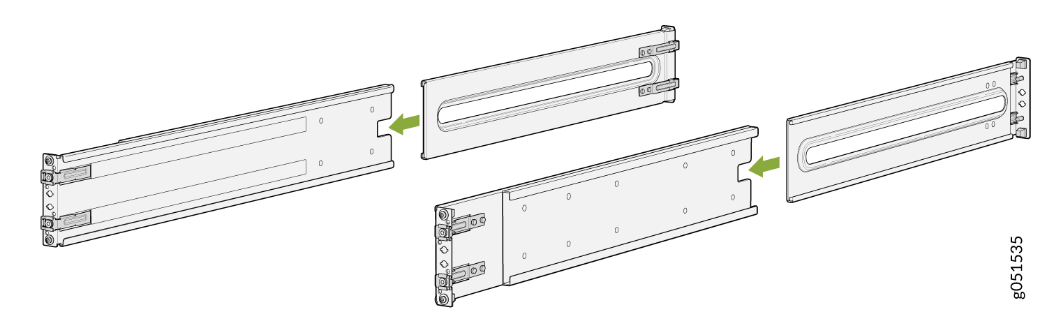
Install the mounting rails on the rack.
Align the guide blocks of the rear mounting rails with the rear-post holes. Pull the rear mounting rails toward the front of the rack to lock the rails in place. You will hear a distinct click sound when the latch locks into the corresponding rack holes.
Figure 3: Install the Rear Mounting Rails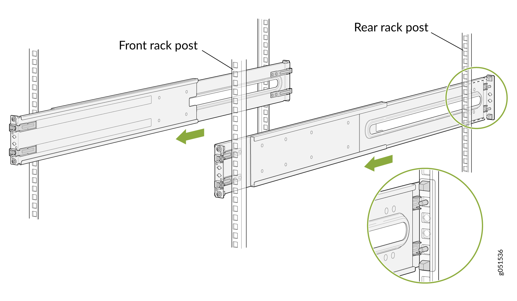
Align the guide blocks of the front mounting rails with the front-post holes. Push the front mounting rails toward the rear of the rack to lock the rails in place. You will hear a distinct click sound when the latch locks into the corresponding rack holes.
Figure 4: Install the Front Mounting Rails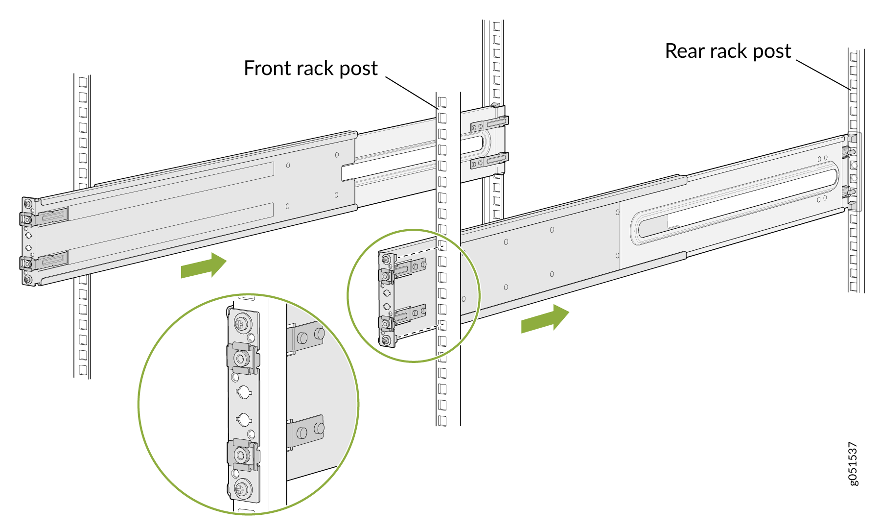
- Visually ensure that the front and rear latches are locked into place on the
mounting rails. The mounting rails should be securely installed on the
rack.Figure 5: Align the side mounting-brackets
Lift the device and position it in front of the rack, aligning the side mounting-brackets with the mounting rails. Slide the device into the channels of the rack mounting rails.
Push the chassis.
Figure 6: Slide the Device into the Rack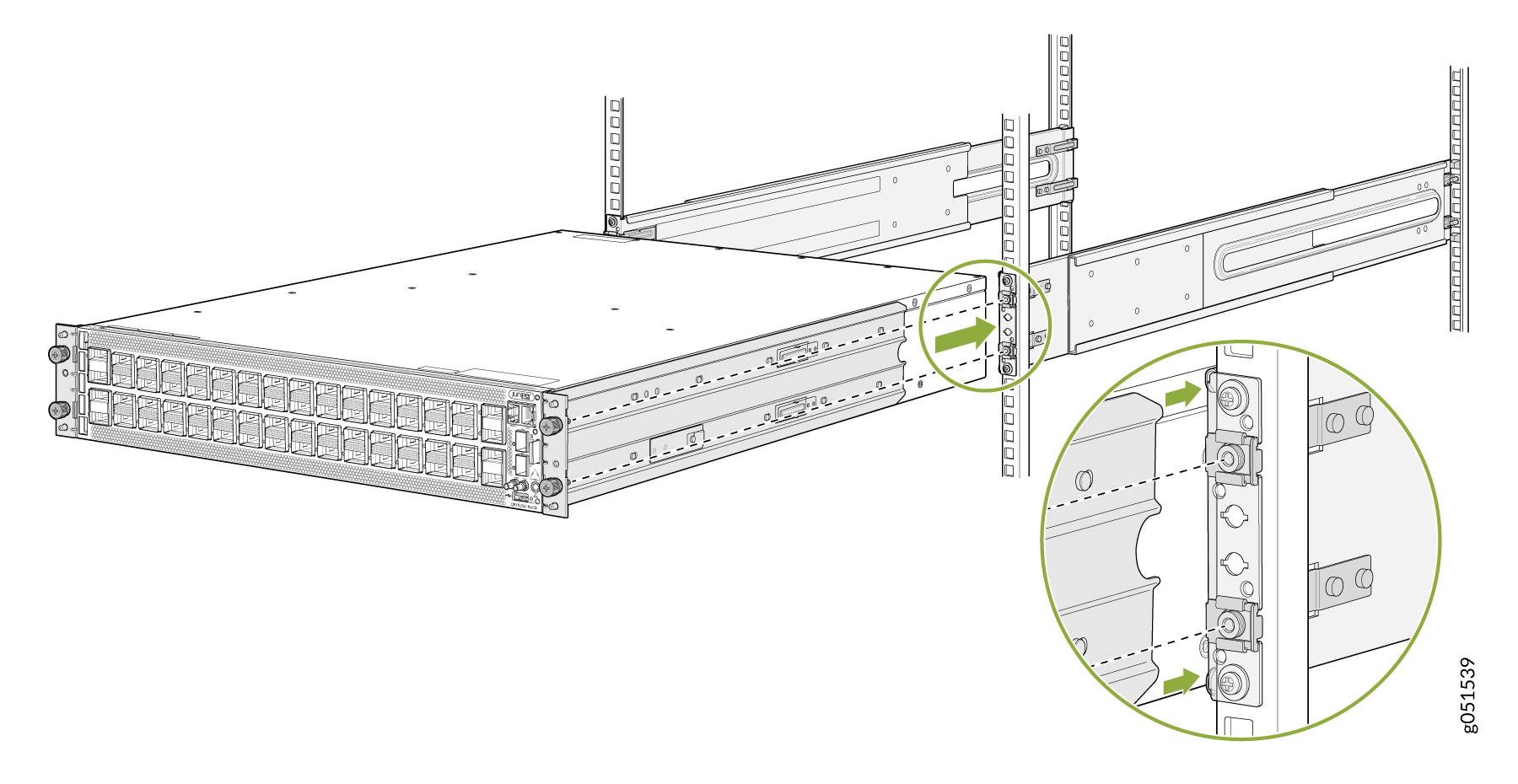
Secure the chassis to the rack and tighten the thumbscrews.
Figure 7: Tighten the thumbscrews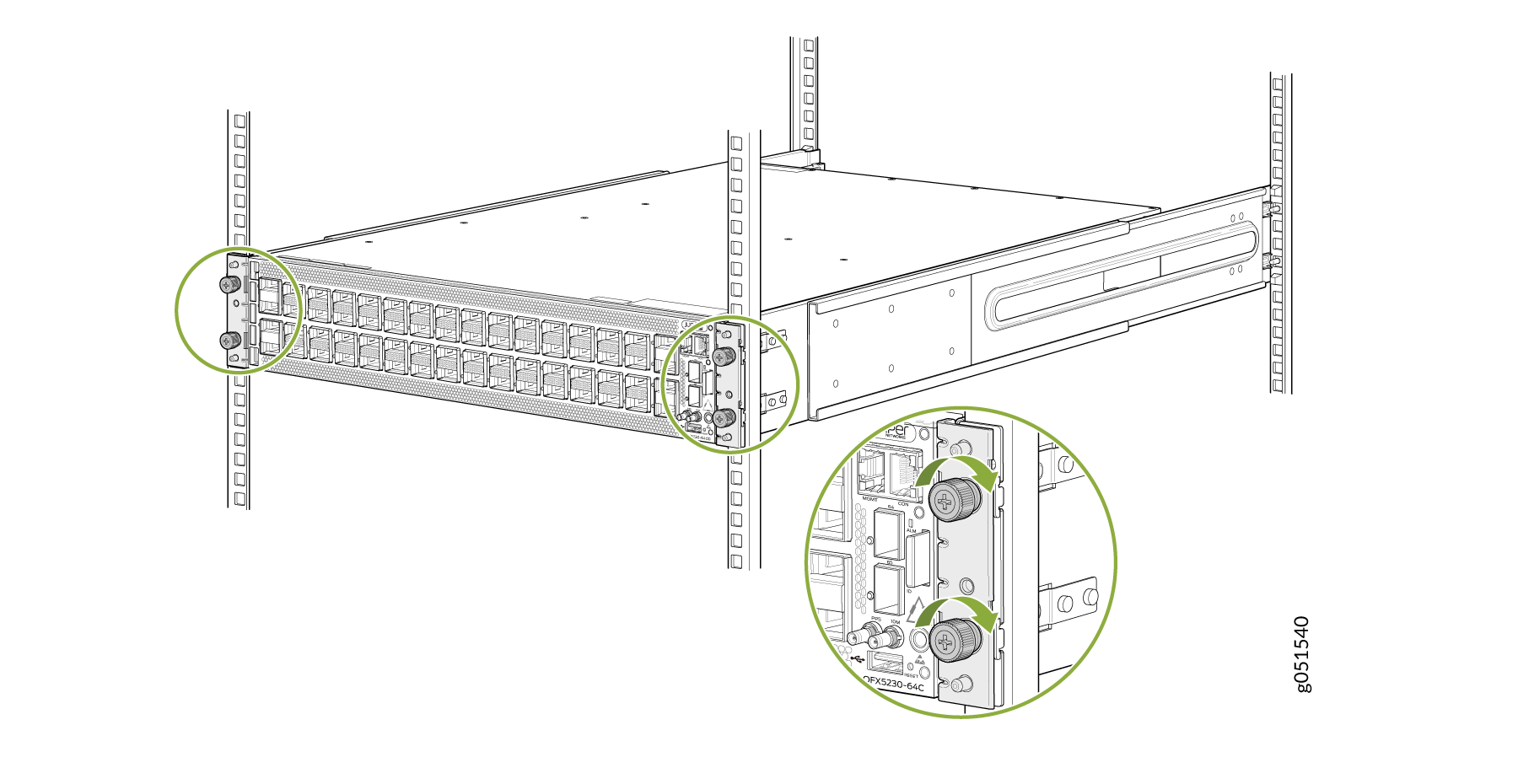
Connect to Power
Ground the QFX5230-64CD Switch
To ground the QFX5230-64CD switch, do the following:
- Connect one end of the grounding cable to a proper earth ground, such as the rack.
- Place the grounding lug attached to the grounding cable over
the protective earthing terminal on the side panel.Figure 8: Attach the grounding cable to QFX5230-64CD
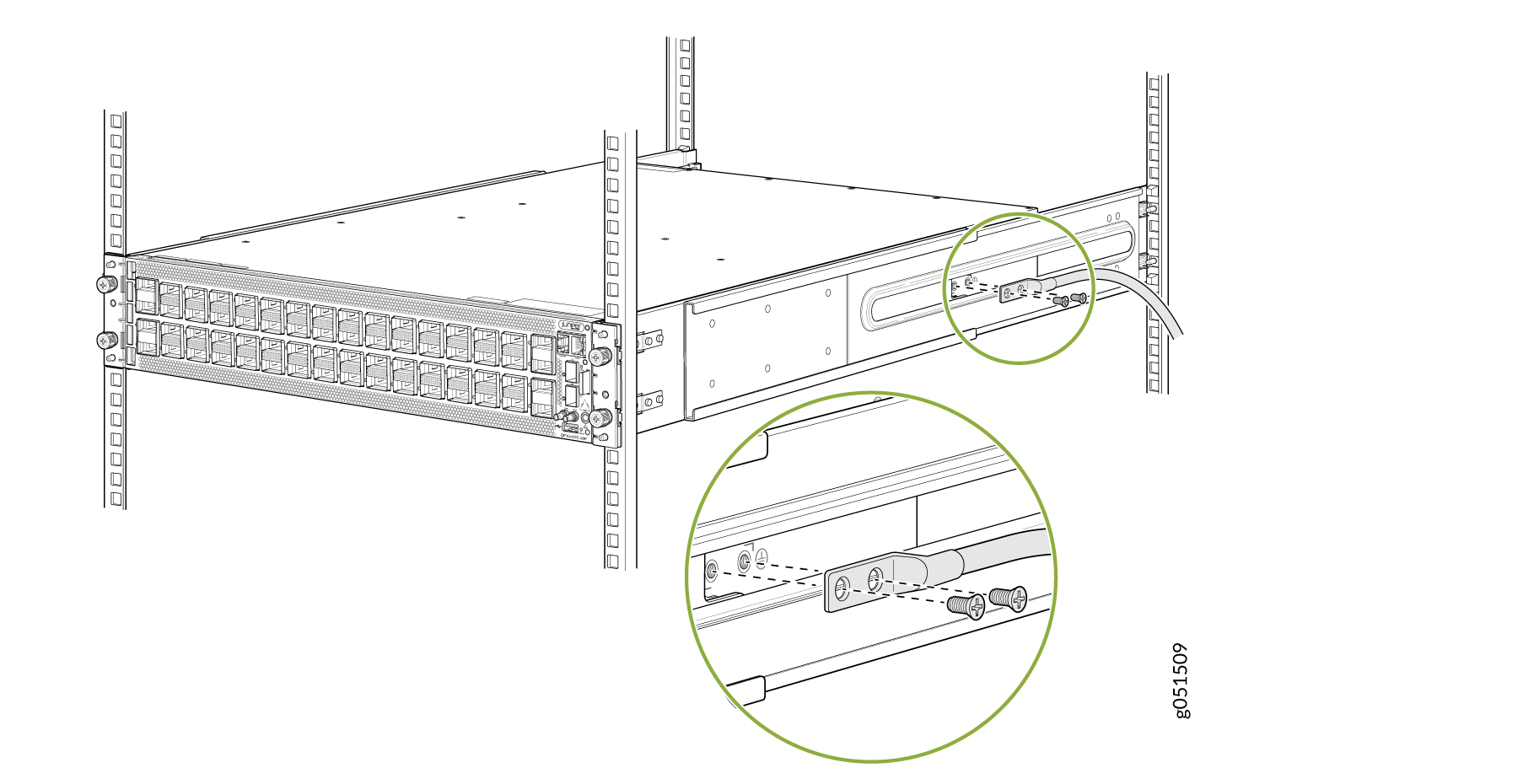
-
Secure the grounding lug to the protective earthing terminal using the 10-32 x .25-in. screws with #10 split-lock washers.
-
Dress the grounding cable. Be sure that the cable doesn’t block access to or touch other device components, and that it doesn’t drape where people could trip over it.
Connect the Power Cord and Power On the Switch
For information about the supported AC power cord specifications, see Table 4.
To connect the power cord, do the following:
-
Ensure that the power supply is fully inserted in the rear panel of the switch and the latches are secured.
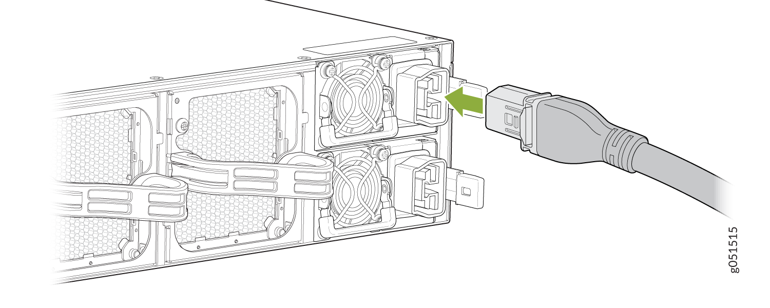
-
If the AC power source outlet has a power switch, turn it off.
-
Plug-in the power cord to the AC power source outlet.
Insert the power cord coupler in the power socket of the switch.
-
If the AC power source outlet has a power switch, turn it on. The switch powers on as soon as you plug it in. The QFX5230-64CD doesn't have a power switch.
-
Check to see that the LED on the power supply is lit steadily green. If the LED stays off, disconnect the power supply from the power source. You’ll need to replace the power supply.