Help us improve your experience.

Let us know what you think.

Do you have time for a two-minute survey?


Connecting the QFX5230-64CD to Power

Ground the QFX5230-64CD Switch

To connect earth ground to a QFX5230-64CD switch:
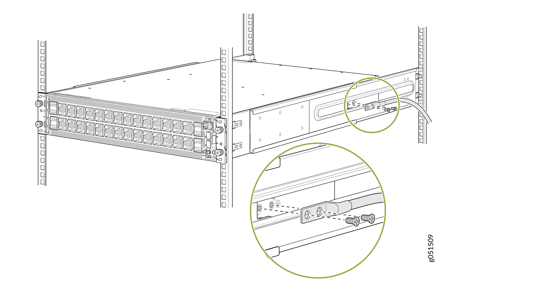
  1. Use two SAE 10-32 x 0.25 in. screws with number10 split-lock washers (not provided) to secure the grounding lug and attached cable (not provided) to the chassis. The posts on the grounding lug should point to the right. See Figure 1.
    Figure 1: Connecting a Grounding Cable to a QFX5230-64CD Switch Connecting a Grounding Cable to a QFX5230-64CD Switch
  2. Connect the other end of the grounding cable to a proper earth ground, such as the rack in which the switch is mounted.
  3. Dress the grounding cable and ensure that it does not touch or block access to other device components and that it does not drape where people could trip over it.

Connect AC Power to a QFX5230-64CD Switch

Before you begin to connect power to the switch, be sure you understand how to prevent ESD damage. See Prevention of Electrostatic Discharge Damage.

Note:

To meet safety and electromagnetic interference (EMI) requirements and to ensure proper operation, you must connect the QFX5230-64CD switch to earth ground before you connect it to power.

Warning:

Before you connect power to the switch, a licensed electrician must attach a cable lug to the grounding and power cables that you supply. A cable with an incorrectly attached lug can damage the switch (for example, by causing a short circuit). To meet safety and electromagnetic interference (EMI) requirements and to ensure proper operation, you must connect the chassis to earth ground before you connect it to power. Under all circumstances, use the protective terminal on the switch chassis to connect to the earth ground.

The AC power supply unit (PSUs) in a QFX5230-64CD switch is a hot-removable and hot-insertable field-replaceable unit (FRU). You can remove and replace it without powering off the switch or disrupting routing functions.

To connect AC power to a QFX5230-64CD switch:

  1. Connect the chassis to earth ground.
    CAUTION:

    To meet safety and electromagnetic interference (EMI) requirements and to ensure proper operation, a QFX5230-64CD switch must be adequately grounded before it is connected to power. For installations that require a separate grounding conductor to the chassis, use the protective earthing terminal on the rear panel of the QFX5230-64CD to connect to the earth ground. A QFX5230-64CD switch gets additional grounding when you plug the power supply in the switch into a grounded AC power outlet by using the AC power cord appropriate for your geographical location.

  2. Ensure that you have taken the necessary precautions to prevent electrostatic discharge (ESD) damage.
  3. Ensure that you have an ESD grounding strap. Wrap and fasten one end of the ESD wrist strap around your bare wrist, and connect the other end of the strap to the ESD point on the device.
  4. If not already installed, install the power supplies in the switch.
    Note:

    Each power supply must be connected to a dedicated power source outlet.

  5. Ensure that the power supplies are fully inserted in the chassis and the latches are secure.
  6. Locate the AC power cords shipped with the QFX5230-64CD switch; the cords have plugs appropriate for your geographical location.
  7. Ensure that you have a power cord appropriate for your geographical location available to connect AC power to the switch.
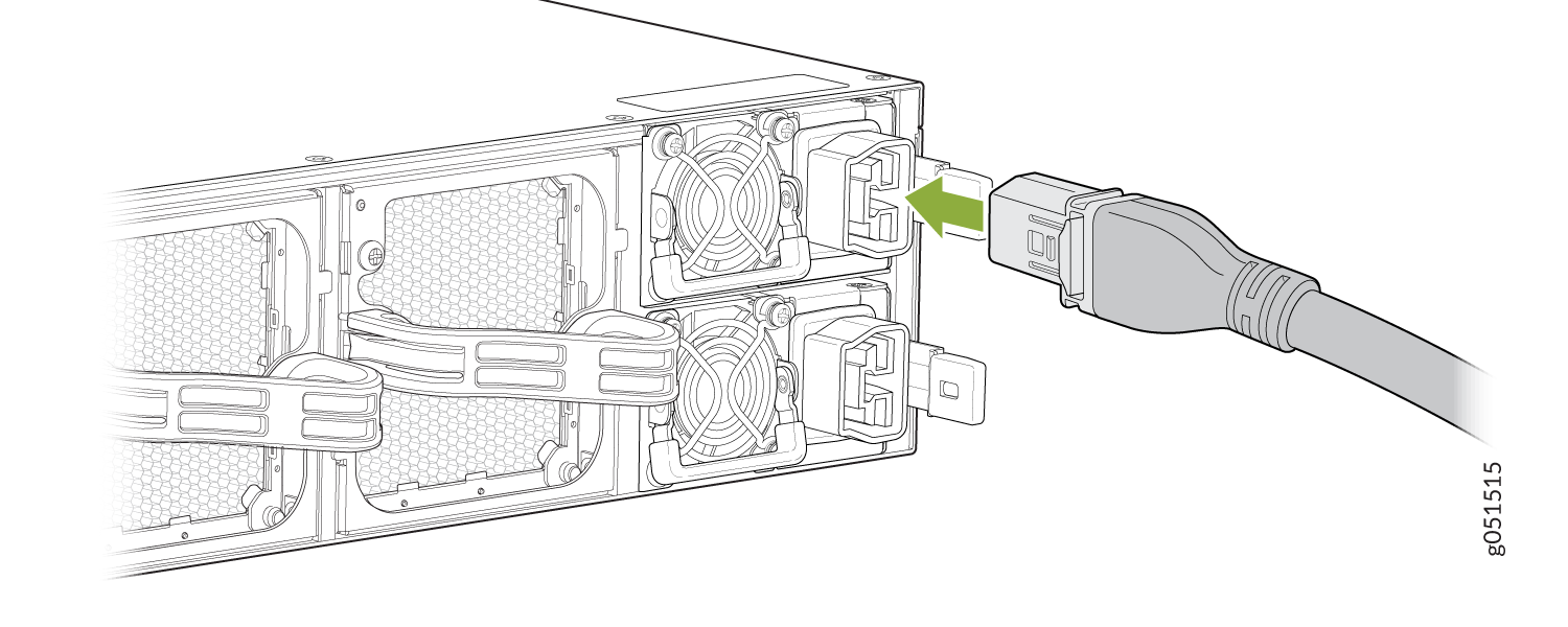
  8. Insert the coupler end of the power cord into the AC power cord inlet on the AC power supply faceplate.
  9. If the AC power source outlet has a power switch, set it to the off (O) position.
    Note:

    The QFX5230-64CD switch powers on as soon as power is provided to the power supply unit. There is no power switch on the power supply unit.

  10. Insert the power cord plug into an AC power source outlet.
  11. If the AC power source outlet has a power switch, set it to the on (|) position.
  12. Verify that the status LEDs on each power supply are lit green. Verify that the status LEDs on each power supply are lit green.

AC Circuit Breaker for the QFX5230-64CD Switch

  1. For Single / multiple feed AC power supply, we recommend that you use a dedicated 2-pole external circuit breaker for each power supply. Each feed of the power supply shall have a dedicated Line and Neutral connection.
  2. We recommend that the rating of the circuit breaker be a minimum of 125% of continuous current drawn by each power supply as per national electric or local code when system is fully configured.
  3. The model number of circuit breaker used for final safety certification is NF100-CN with current rating of 20A and with Medium Delay.
  4. The power supply of this system consists of an internal fuse with 20kA AIC rating.
  5. We recommend that you use appropriate rating of power cord and circuit breaker taking into consideration continuous current drawn when fully configured.
  6. See Table 1 to understand the electrical characteristics for the input fuse within the power supply.
Table 1: Information on Power Supply Fuses for the QFX5230-64CD Switch

Electrical Characteristics

Value

Fuse Littlefuse, 505
Type of fuse (slow, fast) Fast
Voltage rating 500VAC
Current rating 20A
AIC (interrupt rating) 20kA
Approvals UL, IEC
Melting integral 210
Table 2: Recommended AC Breaker Specifications

Electrical Characteristics

Value
Breaker Shihlin Electric, NF100-CN
Delay (short, medium, long). Medium
Type of Breaker Magnetic
Voltage rating 690V
Number of Poles 2-pole
Current rating 20A
AIC (interrupt rating) 7.5kA
Approvals UL, IEC

Connect DC Power to a QFX5230-64CD Switch

Before you begin to connect power to the switch, be sure you understand how to prevent ESD damage. See Prevention of Electrostatic Discharge Damage. When you install the power supplies in the chassis, ensure that the battery returns of the DC power supply gets connected as an isolated DC return (DC-I).
Warning:

Before you connect power to the switch, a licensed electrician must attach a cable lug to the grounding and power cables that you supply. A cable with an incorrectly attached lug can damage the switch (for example, by causing a short circuit). To meet safety and electromagnetic interference (EMI) requirements and to ensure proper operation, you must connect the chassis to earth ground before you connect it to power. Under all circumstances, use the protective terminal on the switch chassis to connect to the earth ground.

  • Ensure that you have the following parts and tools available:

    • ESD grounding strap

    • Screwdriver

    • Nutdriver, with a torque range between 23 lb-in (2.6Nm) to 25 lb-in (2.8Nm)

      CAUTION:

      You must use an appropriate torque-controlled tool to tighten the screws on the DC power cable connector. Do not overtighten the screws. Applying excessive torque damages the terminal block and the wiring tray. The absolute maximum torque that may be applied to this screw is 25 lb-in (2.8Nm).

    • Two DC power source cables. The QFX5230-64CD switch supports a 4-AWG and 75°C temperature-rated stranded copper wire.
CAUTION:

Do not mix AC and DC power supplies in the same chassis. Each power supply must be connected to a dedicated power source.

The DC power supply in a QFX5230-64CD switch is a hot-removable and hot-insertable field-replaceable unit (FRU). You can remove and replace it without powering off the switch or disrupting switch functions. You do, however, need to disconnect power supply before attempting to remove the unit.

Warning:

The DC-powered QFX5230-64CD switch models are intended for installation in a restricted access location only.

To connect DC power to a QFX5230-64CD switch:

  1. To prevent damage to the equipment caused by static discharge, attach an ESD grounding strap to your bare wrist, and connect the strap to an approved site ESD grounding point.
  2. Ensure that the power supplies are fully inserted in the chassis and that the latches are secure.
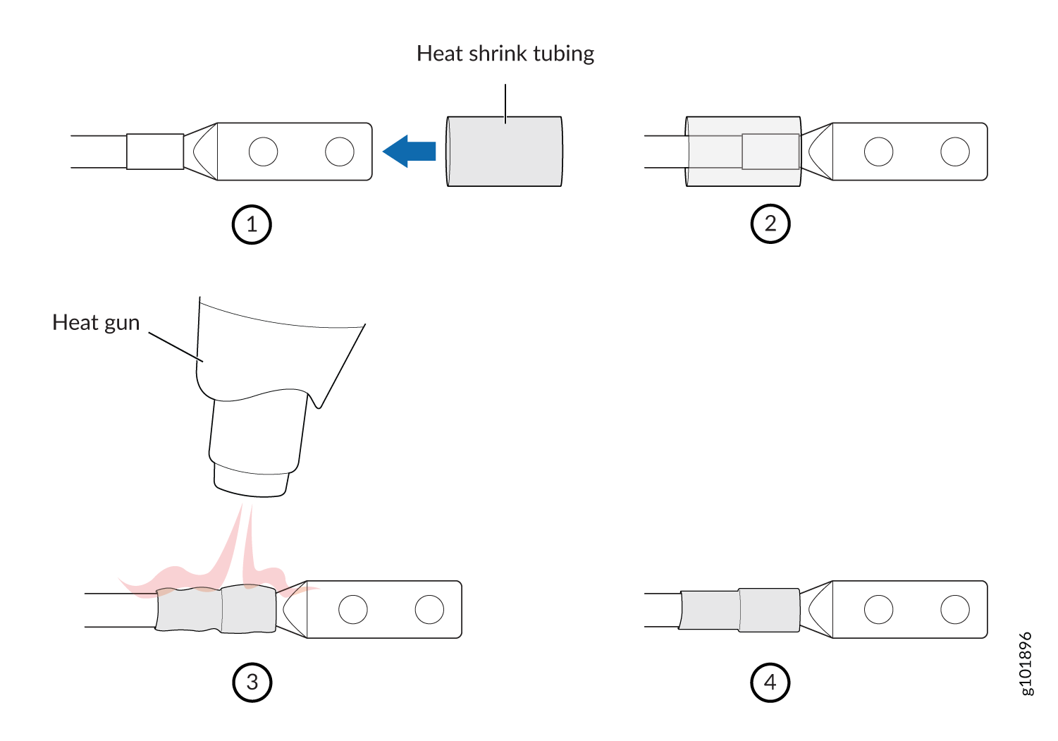
  3. Install heat-shrink tubing insulation around the power cables.
  4. To install heat-shrink tubing: Slide the tubing over the portion of the cable where it is attached to the lug barrel. Ensure that tubing covers the end of the wire and the barrel of the lug attached to it. Shrink the tubing with a heat gun. Ensure that you heat all sides of the tubing evenly so that it shrinks around the cable tightly.
    Note: Make sure that you do not overheat the tubing.
  5. Remove the cover on the DC terminals using a screwdriver.
  6. Remove the nuts from the DC terminals.
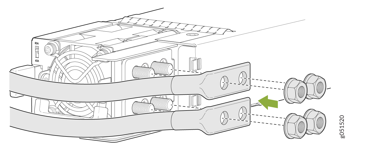
  7. Connect each power supply to the power source by inserting the DC connector into the power supply. Connect each power supply to the power source by connecting DC power cable to the power supply. The DC PSM has two terminals labeled -48V/-60V (negative) and RTN (positive) for connecting the DC power cables labeled positive (+) and negative (-). The terminals are covered by a cover on the terminal block. See Figure 2.
    Figure 2: Connecting a Straight DC Power Cable to a DC Power Supply in a QFX5230-64CD Switch Connecting a Straight DC Power Cable to a DC Power Supply in a QFX5230-64CD Switch
    Warning:

    Ensure that the power cables do not block access to device components or drape where people can trip on them.

  8. Using the nutdriver, tighten the nuts on the power cable connector to between 23 lb-in (2.6Nm) to 25 lb-in (2.8Nm).
    CAUTION:

    You must use an appropriate torque-controlled tool to tighten the nuts. Applying excessive torque damages the terminal block and the wiring tray. The absolute maximum torque that may be applied to this nut is 25 lb-in (2.8Nm).

  9. Repeat 4 through 7 for each power supply that you are connecting to power.
  10. Close the input circuit breaker. We recommend that the 48 VDC facility DC source be equipped with a circuit breaker rated at 80A (125VDC) minimum, or as required by local code.
    CAUTION:

    The connection between each power source and PSM must include a circuit breaker. For single/ multiple feed DC power supply, we recommend that you use a dedicated external circuit breaker for each of the power supplies. Use a 2-pole circuit breaker if both -48V and return feeds are isolated. Use a single pole circuit breaker if one of the feeds are connected to ground. Install this single pole circuit breaker in the ungrounded side of the supply. We recommend that the rating of the circuit breaker is a minimum 125% of the continuous power drawn by each power supply as per the national electric or local code when the system is fully configured. The model number of circuit breaker used for final safety certification is CA2-B0- 16-680-621-BJ with current rating of 80Amps and with long delay. We recommend that you use appropriate rating of the input DC wire taking into consideration continuous current rating of the system when it is fully configured and the circuit breaker rating.

    Table 3: External DC Circuit Breaker Electrical Characteristics

    Electrical Characteristics

    Value

    Breaker Carling Technologies, CA2-B0- 16-680-621-BJ
    Delay (short, medium, long). Long
    Type of Breaker Magnetic
    Voltage rating 125VDC
    Number of Poles 2-pole
    Current rating 80A
    AIC (interrupt rating) 5kA
    Approvals UL, IEC
  11. Verify that the LED on the power supply is lit green and is on steadily.
  12. If the status LED is lit amber, disconnect power to the switch, and replace the power supply. Do not remove the power supply until you have a replacement power supply ready. The power supplies must be installed in the QFX5230-64CD switch to ensure proper airflow.
    Note:

    Replace a failed power supply with a new power supply within 30 seconds of removal to prevent overheating.